M-Elec Apex Series User manual

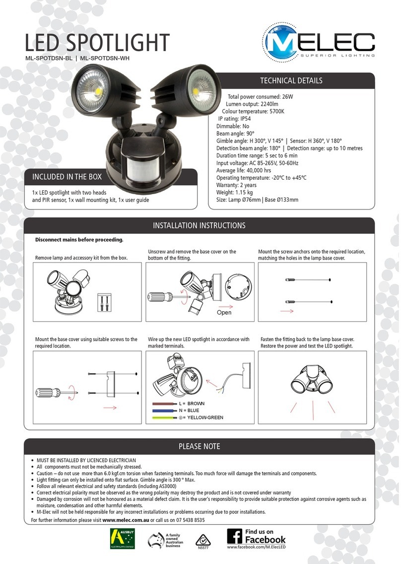
The new spot range has been designed to fix all the frustrations that electricians face with current spot lights. The
2 part easy-connect base installs onto the wall or ceiling with plenty of space for cable termination with entry from
back or base (20mm conduit) and the body of the light uses custom guides to slide onto the base perfectly making
solid cable-free connections with the pin terminals. The sensor has been created to feature a double gimbal action
allowing for both horizontal and vertical adjustments. This is a perfect example of another product designed by
electricians for electricians
Spotlights
Product information
OUR FULL RANGE Available in black or white with or without sensor
12W* 12W* 24W* 24W*
850lm
1000lm
950lm
850lm
1000lm
950lm
1700lm
2200lm
1900lm
1700lm
2200lm
1900lm
3000K
4000K
6000K
3000K
4000K
6000K
3000K
4000K
6000K
3000K
4000K
6000K
IP54 IP54 IP54 IP54
Up to 85lm/W Up to 85lm/W Up to 90lm/W Up to 90lm/W
80+ 80+ 80+ 80+
90° 90° 90° 90°
No No No No
Built in Driver
Built in Driver
Built in Driver
Built in Driver
40,000 hrs** 40,000 hrs** 40,000 hrs** 40,000 hrs**
N /A N /A
Ye s Ye s Ye s Ye s
N /A °
N /A °
N /A N /A
N /A N /A
N /A N /A
Base: Ø 120mm
Base: Ø 120mm
Base: Ø 120mm
Base: Ø 120mm
0.4kg 0.5kg 0.6kg 0.7kg
5 Years 5 Years 5 Years 5 Years
sensor
sensor
*Total power consumed including driver
** Average life is calculated on expected average lifespan
Apex
Black 12W
White 12W
Black 12W
White 12W
Black 24W
White 24W
Black 24W
White 24W
TECHNICAL INFORMATION

INSTALLATION GUIDE
Remove lamp from the box, unscrew and remove the
base cover in the centre of the fitting.
Pull the cable through the cable hole (either penetrate
the rubber cap or break away the bottom knock out and
use appropriate sealant to retain IP protection).
Wire up the light in accordance with the marked
terminals:
*L - Out is used to conect other lights to the sensor
(optional, max load 70W inc fitting draw)
Ensure cables are tidied in the cable space area on the
left ().
on the switch inside main body.
When installing the main body back to the base make
sure, the locating pins on main body go into the slots on
the base. Once installed, secure the main body onto the
base with the screw that you removed in step 1.
Screw GuideScrew Guide
Screw Guide
Screw Guide
Rubber Cap
Knock Out
Cable Space
Sensor OUT

OPTIONAL FOR SENSOR VERSION:
ADJUSTING THE TIME DURATION
ADJUSTING THE LUX CONTROL LEVEL
The Lux control module has a built-in sensing device (photocell) that detects daylight and darkness. The (sun) position denotes that the spotlight
will work at day and night, and the (moon) position will only work at night. You can set the unit to operate at the desired level by adjusting the LUX
knob from light (sun) to dark (moon).
SETTING THE CONTROLS SEQUENCE
Turn the Lux control knob to light (sun) position, turn the wall switch on and wait half a minute for the control circuit to stabilize. At this stage
Direct the sensor toward the desired area to be scanned by adjusting the elbow joint and the swivel joint on the sensor arm. Important: loosen all
lock nuts and screws on sensor and lamp holders before making any adjustments.
presence of the moving person, causing the spotlights to switch on.
To set the light level at which the spotlights will automatically switch “on” at night, turn the LUX control knob from daylight (sun) to night-time
daylight (sun) while someone walks across the centre of the area to be detected. When the spotlight switches on, correct LUX level has been
established. You may need to make further adjustments to achieve your ideal light level setting.
MANUAL OVERRIDE
The light can stay ON for 8h time periods by using the manual override function.
To activate manual override function, flick the switch off/on/off/on within 3 seconds. The light will stay on for 8 hours and then return to normal
sensor operation.
DUAL AXIS SENSOR:
Adjust horizontally or vertically - Do not rotate!
145°
°

PLEASE NOTE
• Read instructions carefully before attempting to install the fitting. Retain this guide for future reference
• Disconnect power before installing or servicing
• This fitting is for outdoor use and should not be used in areas with limited ventilation or high ambient temperatures
• Do not extend low voltage cables from the output of power supply
• All components must not be mechanically stressed
• Be careful not to damage or destroy conductive paths on the circuit board
• 000)
•
• Damage by corrosion will not be honoured as a material defect claim. It is the user’s responsibility to provide suitable protection against
corrosive agents such as moisture, condensation and other harmful elements
This manual suits for next models
8
Other M-Elec Spotlight manuals
Popular Spotlight manuals by other brands
Powerfix Profi
Powerfix Profi PLS 10 A2 Operating instructions and safety instructions
Honeywell
Honeywell LED150 instruction manual

Viewpoint
Viewpoint 20005 owner's manual
Federal Signal Corporation
Federal Signal Corporation VISIBEAM II Installation, operation and maintenance instructions

Craftsman
Craftsman CMXLSBWP5 user manual
TECH LIGHT
TECH LIGHT SL-3445 user manual
