NovaCHARGE NC7000 Series User manual
Installation Manual
NC7000 Series
EV Charger-32A
© NovaCHARGE 2019 - All Rights Reserved C
Need Help?
Contact the NovaCHARGE support team at 866-417-9995 or
support@novacharge.net.
Date of Purchase: __________________________________________________
Installation Location: _______________________________________________
________________________________________________________________
________________________________________________________________
________________________________________________________________
________________________________________________________________
IMPORTANT SAFETY INSTRUCTIONS
This document contains instructions and warnings that must be followed when install-
ing and using the Electric Vehicle Supply Equipment (EVSE). Before installing or using the
EVSE, read this entire document as well as all WARNING and CAUTION markings in this
document.
Safety Instructions
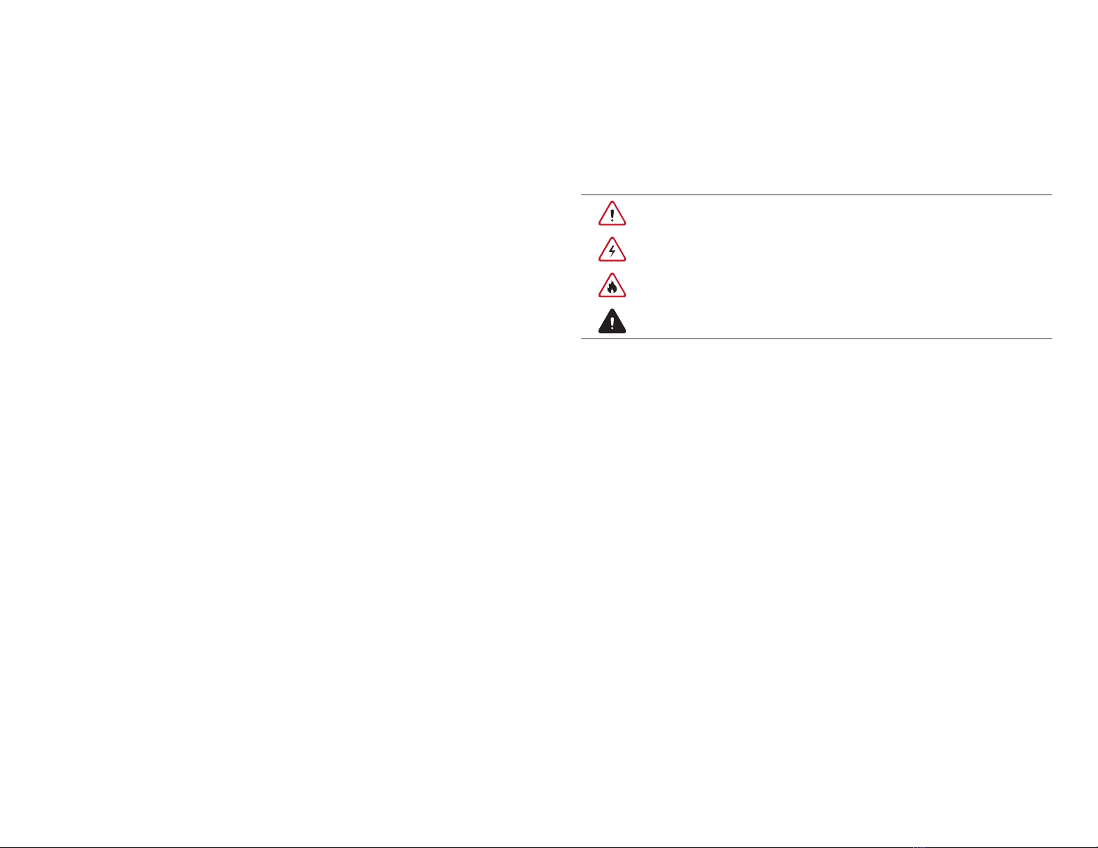
The symbols used have the following meaning:
WARNING: RISK OF PERSONAL INJURY
WARNING: RISK OF ELECTRIC SHOCK
WARNING: RISK OF FIRE
CAUTION: RISK OF DAMAGE TO THE EQUIPMENT
• The NC7000 series charger must only be installed by licensed electricians.
• Make sure that all materials used during the installation procedures follow local
building codes and safety standards.
• The information provided in this manual in no way exempts the user or installer
of their responsibility to follow all applicable codes or safety standards.
• This document provides specific installation instructions for the NC7000 series
charger and should not be used for any other product.
• Before installation or use of this product, review this manual carefully and consult
with a licensed contractor, licensed electrician, or trained installation expert to
ensure compliance with local building codes and safety standards.
Repair and Maintenance Clause
• Only licensed electricians should repair or maintain the NC7000 series charger.
• Turn off the input power before performing any installation, repair or mainte-
nance work.
FCC Declaration of Conformity
• This NC7000 series charger complies with part 15 of the FCC Rules. Changes or
modifications to this charger not expressly approved by the manufacturer could
void FCC compliance.
• Operation is subject to the following conditions: (1) This charger may not cause
harmful interference, and (2) This charger must accept any interference received,
including interference that may cause undesired operation.
© NovaCHARGE 2019 - All Rights Reserved 1
NC7000 Installation Manual
D
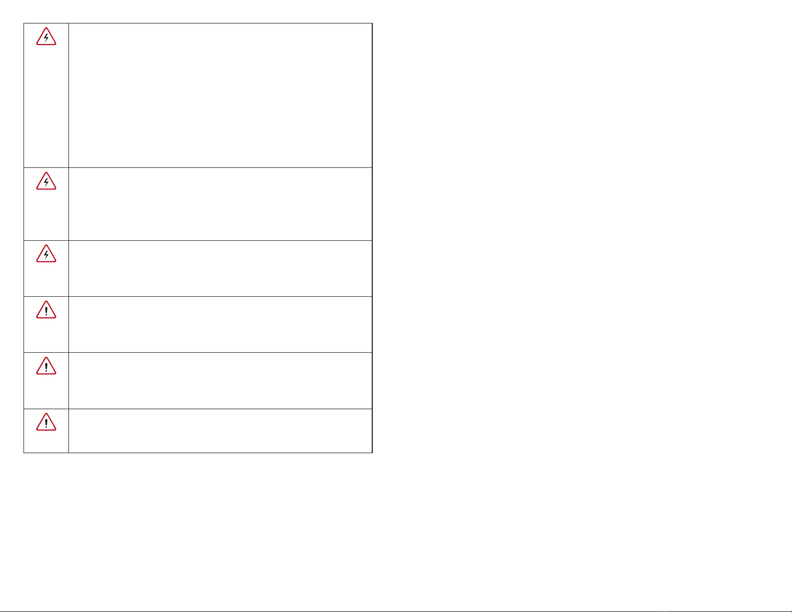
WARNING: RISK OF ELECTRIC SHOCK
Basic precautions should always be followed when using electrical prod-
ucts, including the following:
• Read all the instructions before using this product.
• This charger should be supervised when used around children.
• Do not put fingers into the EV connector.
• Do not use this product if the flexible power cord or EV cable is
frayed, has broken insulation, or any other signs of damage.
• Do not use this product if the enclosure or EV connector are bro-
ken, cracked, open, or if they show any other damage.
WARNING: RISK OF ELECTRIC SHOCK
Improper connection of the equipment grounding conductor can result in
a risk of electric shock. Check with a qualified electrician or serviceman if
you are in doubt as to whether the product is properly grounded.
WARNING: RISK OF ELECTRIC SHOCK
• Do not touch live electrical parts.
• Incorrect connections may cause electric shock.
WARNING: This equipment is intended only for charging vehicles that do
not require ventilation during charging. Please refer to your vehicle owner’s
manual to determine ventilation requirements.
WARNING: Do not use extender cables to increase the length of the
charging cable. Maximum length is limited to 25 feet by the National Fire
Protection Agency.
WARNING: Do not drag the NC7000 series charger by the input power
cord.
SAVE THESE INSTRUCTIONS
CONTENTS
1 Introduction ..........................................................................................................................2
1.1 Product View ........................................................................................................................2
2 Installation .............................................................................................................................4
2.1 Before Installation ..............................................................................................................4
2.2 Tools & Parts Required for Installation .......................................................................5
2.3 Mounting the Charging Station .....................................................................................6
2.4 NC7000 Series Charger Installation with NEMA 6-50 Plug .................................6
2.5 NC7000 Series Charger Hardwire Installation ..........................................................9
2.6 Holster Installation ............................................................................................................12
© NovaCHARGE 2019 - All Rights Reserved 3
NC7000 Installation Manual
2
1. Introduction
This user manual applies to “NC7000 Series 32A Level 2 AC Charger for Plug-in Electric
Vehicles (PEVs) and Battery Electric Vehicles (BEVs)”.
With a 32A maximum capability, the NC7000 series can be programmed to the energy
output required.
Any unauthorized modifications will void the manufacturer’s warranty
1.1 Product View
Different models of Charger:
NC7000 Series Charger (Hardwired) NC7000 Series Charger (NEMA 6-50)
Figure 1-1 NC7000 Series Charger Front view
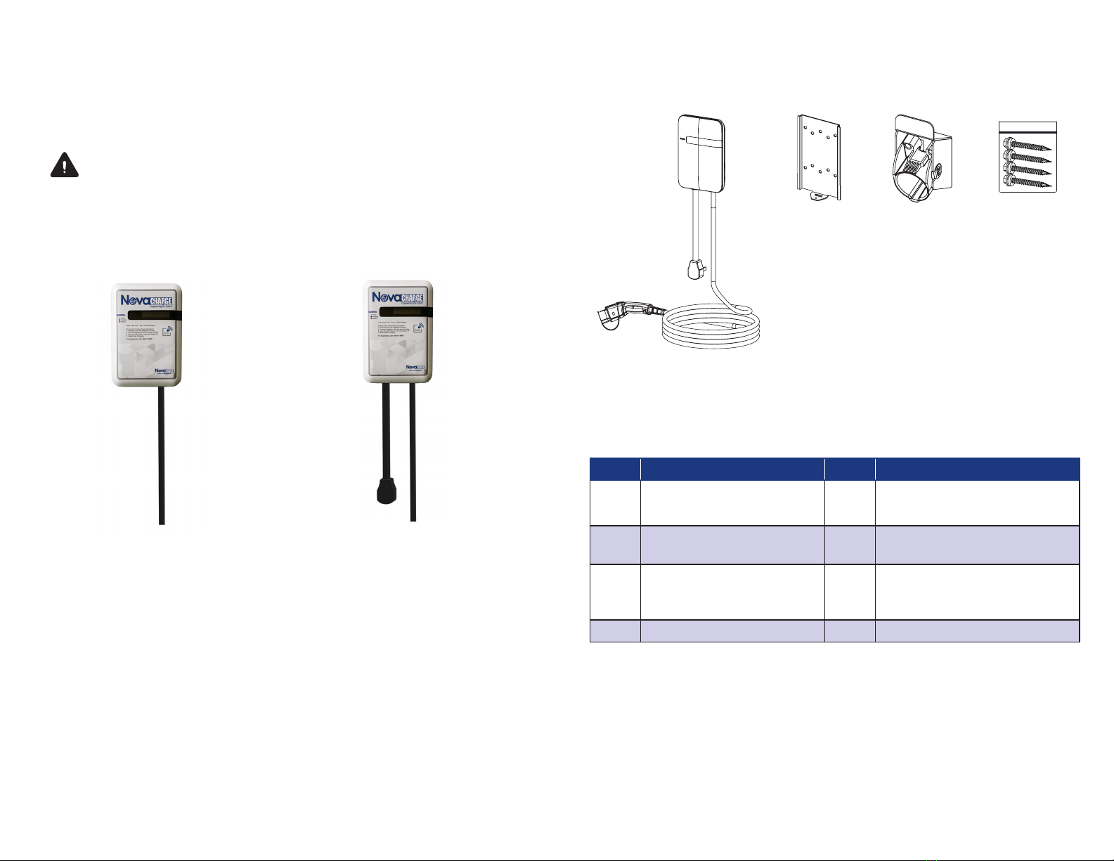
Box Contents
Figure 1-2 Box contents
Table 1-1 Accessories in the box
Item Description Qty. Note
1 NC7000 Series (NEMA 6-50) or
NC7000 Series (Hardwire)
1
2 Mounting Bracket with
M4 Screw
1 Bracket is attached to back of
charger
3 Holster Assembly 1 Quantity 2 M4xL15 tapping screws
(already installed in Holster
Assembly)
4 Wall Mount Screw Bag 1 Quantity 4 Tapping #12 screws
© NovaCHARGE 2019 - All Rights Reserved 5
NC7000 Installation Manual
4
2. Installation
2.1 Before Installation
2.1.1 Safety check
CAUTION: Disconnect the power supply before installing or
repairing the charger. Failure to disconnect may result in
physical injury or damage to the power supply system and
the charging unit.
The NC7000 series charger must be installed only by a licensed electrician in
accordance with local and national electrical codes and standards.
Before installing the charger, make sure you have read all the instructions in this
manual and fully understand its contents.
Appropriate protection is required when connecting to a main switchboard. Please
refer to section 2.2, Tools and Parts Required for Installation.
2.1.2 Grounding Instructions
NEMA 6-50 Cord Connected Product: This product comes with a
NEMA 6-50 cord that contains an equipment grounding conductor and
a grounding plug. The plug must not be modified in any way and must
be plugged into a suitable properly-grounded outlet. Failure to follow
this advice could result in electric shock or death. Check with a qualified
electrician if you are unsure if the product is properly grounded.
Hardwired Connected Product: Grounding Instructions for a hardwired
connected product: This product must be connected to a grounded,
metal, permanent wiring system; or, an equipment-grounding conductor
must be run with the circuit conductors and connected to the
equipment
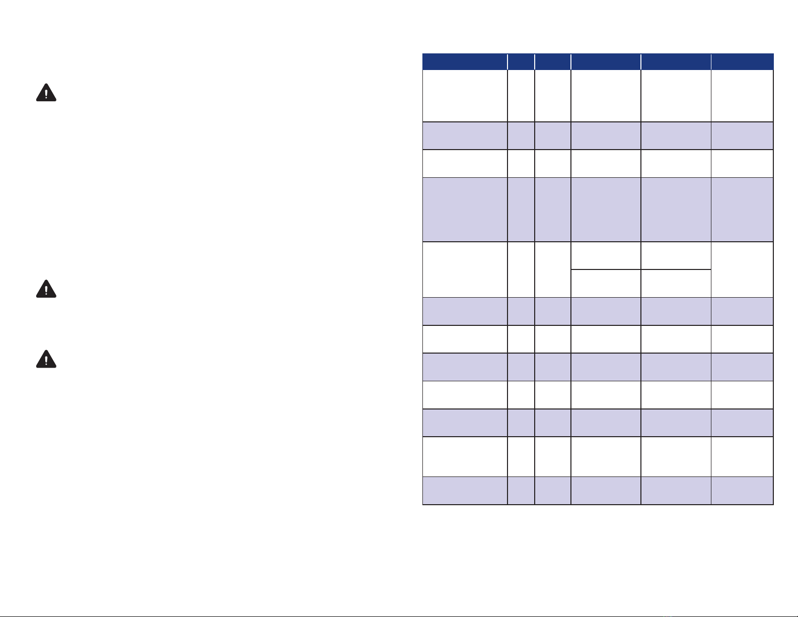
2.2 Tools and Parts Required for Installation
Tool Qty. Model Size Supplier Remark
Mounting Bracket 1 All 194x109x9 mm Model
Accessories
Fasten
NC7000
series charger
to the wall
Holster Assembly 1 All 58x58x70 mm Model
Accessories
Hold EV
charging plug
Heat Shrink Tubing 3 IC3 For 8 AWG
wire
Model
Accessories
Protect wires
& terminals
Terminal 3 IC3 For 8 AWG
wire
Model
Accessories
Connect
input wires
to the
terminal
block
Screws 4 All Tapping #12 Model
Accessories
Fasten
Mounting
Bracket &
Hook
Mechanical:
M6
Commercially
Available
Heat Gun 1 ALL Standard size Commercially
Available
For heat
shrink tubing
Wire, Copper 3 IC3 8 AWG Commercially
Available
UL1015
(recommended)
Conduit 1 IC3 1 inch Commercially
Available
Protect
power cable
Torx Screwdriver 1 All T20 Commercially
Available
Philips Screwdriver 1 All PH3 Commercially
Available
Hexagon Socket 1 All 5/16 Commercially
Available
Tighten
tapping
screws
Torque Wrench 1 All 35 kgf-cm min Commercially
Available

© NovaCHARGE 2019 - All Rights Reserved 7
NC7000 Installation Manual
6
2.3 Mounting the Charging Station
NOTE: If mounting onto a NovaCHARGE Universal Pedestal, please follow the
instructions that accompanied the pedestal.
To prepare for mounting, remove the mounting bracket from the back of the
charger by loosening the M4 screw.
2.4 NC7000 Series Charger Installation with NEMA 6-50 Plug
1. Secure the main body mounting bracket to the wall (or pedestal) with the
appropriate screws.
In order to meet ADA requirements, please use the following heights:
• For an indoor site, the charger should be located no lower than 18” (450 mm) and
not higher than 48” (1.2m).
• For an outdoor site, it is not lower than 24” (609 mm) and not higher than 48”
(1.2m). Refer to Article 625, NEC.
Standard installation requires that only two screws are used to fasten the mounting
bracket, using the two middle screw holes. The additional screw holes may be used
based on individual requirements.
Figure 2-1 Fasten mounting bracket Figure 2-2 Screw holes of mounting bracket
Screw sizing suggestion:
A. For masonry walls, use M6 mechanical screws. (Commercially Available)
B. For finished walls supported by wood studs, use #12 tapping screws.
(Model Accessories)
C. Please refer to the following torque. The actual torque is according to the
wall material.
2. Mount the NC7000 series charger onto mounting bracket.
• Slide the charging unit onto the mounting bracket.
• Fasten by tightening the M4 screw attached to mounting.
Please use the following torque.
Figure 2-3 NC7000 Series Charger and mounting bracket
Figure 2-4 Tighten M4 screw
Screw Torque
M6 25 kgf.cm min 21.7 lb-in min
#12 25 kgf.cm min 21.7 lb-in min
Screw Torque
M4 16 kgf.cm 13.88 lb/in

© NovaCHARGE 2019 - All Rights Reserved 9
NC7000 Installation Manual
8
3. Plug in the power cord.
Install the NEMA 6-50 outlet so that it is located at 6 - 10 inches below the NC7000
series charger, as shown in the figure below.
Figure 2-5 Plug in the power cord
2.5 NC7000 Series Charger Hardwire Installation
1. Disassemble the front cover, by loosening the star screws (x5).
Figure 2-6 Position of five screws on Base Cover
2. Choose the appropriate conduit in accordance with all applicable state, local and
national electrical codes and standards.
Fi gu re 2 -7 Con d u i t . Figure 2-8 Right angle conduit

© NovaCHARGE 2019 - All Rights Reserved 11
NC7000 Installation Manual
10
3. Clamp the copper terminals (model accessories) to copper wires. Cover the clamp
point with heat shrink tube (model accessories) for protection.
3.1 Refer to the following wire specification. Use conductor type other than RHH,
RHW and RHW-2 with outer covering.
Model Terminal Conductor Rating
NC7000 Series L1, L2,G 8 AWG 90C copper wire
Figure 2-9 Copper terminal, heat shrink tube and copper wire.
4. Electrical wiring to the NC7000 series charger.
4.1 Begin with the top cover disassembled.
4.2 Use a Philips screwdriver to remove the clear plastic safety cover and remove
terminal screws.
4.3 Fasten the conduit to the enclosure. Please refer to the following torque.
4.4 Insert the wire and attach to the terminal block as shown in Figure 2-10
4.5 Use the following torque to connect the wire terminals to the terminal block
and replace clear plastic safety cover.
Input Terminal Block
,QSXW7HUPLQDO%ORFN
Figure 2-10 Input wiring
CAUTION: To reduce the risk of fire, connect only to a circuit provided
with 40 amperes maximum branch circuit overcurrent protection in accor-
dance with the National Electrical Code, ANSI/NFPA 70, and the Canadian
Electrical Code, Part I, C22.1.
Conduit Torque
1“ 35 kgf.cm 30.36 lb-in
Screw Torque
M4 16 kgf.cm 13.88 lb-in
Model Current Rating
NC7000 Series 32 A

© NovaCHARGE 2019 - All Rights Reserved 13
NC7000 Installation Manual
12
4.6 Reassemble top cover. Please refer to the following torque. This is a critical step, as
proper torqueing of these screws is necessary to ensure the front cover enables a
weather and moisture resistant fit.
2.6 Holster Installation
NOTE: If mounting onto a NovaCHARGE Universal Pedestal, please follow the
instructions that accompanied with the pedestal.
1. Separate the holster from the hook.
Figure 2-11 Separate the holster
2. Fasten the hook on the wall (or pedestal) with appropriate screws.
• For finished walls supported by wood studs use #12 tapping screws (x2).
• The recommended torque is 25 kgf.cm (21.7 lb-in).
Figure 2-12 Secure the hook
Screw Torque
M4 16 kgf.cm 13.88 lb-in
3. Make the holster face up and combine with the hook.
Figure 2-13 Secure the holster
4. Completely rotate the holster into place.
Figure 2-14 Rotate the holster

© NovaCHARGE 2019 - All Rights Reserved 15
NC7000 Installation Manual
14
5. Keeping the holster in this state, tighten screws completely.
• The recommended torque is 6 kgf.cm (5.2 lb-in). The screws will make the
combination firm.
Figure 2-15 Secure the hook
6. Place the NC7000 series charging plug on the holster.
Figure 2-16 Place NC7000 series charging plug.
Congratulations! You have successfully
completed the installation of your new
NC7000 Series EV Charger.

US Toll Free: (866) 417-9995 • 1 (813) 333-1119
www.novacharge.net
© NovaCHARGE 2019 - All Rights Reserved
Table of contents
Other NovaCHARGE Batteries Charger manuals


