manuals.online logo
Brands
  1. Home
  2. •
  3. Brands
  4. •
  5. NOVAK
  6. •
  7. Controllers
  8. •
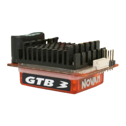
  9. NOVAK GTB - PROFILE SELECTION AND PROPER GEARING User manual

NOVAK GTB - PROFILE SELECTION AND PROPER GEARING User manual

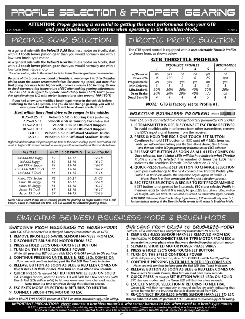
The GTB is equipped with 6 user-selectable Throttle Profiles, as shown below.
GTB THROTTLE PROFILES
BRUSHLESS PROFILES
BRUSH-MODE
1 2 3 4 5 6
w/Reverse
no yes no no yes no
Reverse%
0 100 0 0 25 n/a
Programmable yes yes yes yes no yes
Min.Brake%
9% 9% 9% 21% 9% 9%
Drag Brake
9% 9% 9% 21% n/a off
Dead Band%
5 5 5 5 5 5
Min.Drive%
1 1 3 3 1 3
NOTE: GTB is factory set to Profile #1
The GTB will always revert back to Profile #1 when the One-Touch set-up is performed.
selecting brushless profiles
:
all LEDs
With ESC on & connected to a charged battery
(transmitter ON or OFF)
:
1.
IF TRANSMITTER IS OFF, DISCONNECT ESC FROM RECEIVER
To avoid possible radio interference from other transmitters, remove the
ESC’s input signal harness from the receiver.
2. PRESS & HOLD THE ESC’S ONE-TOUCH SET BUTTON
Continue to hold SET button on ESC until all 4 LEDs turns on.
Note: you will continue holding past the Blue, Blue & Amber, Blue & Green, Amber,
and then the Amber & Red LED programming indicators in the ESC’s software.
3.
RELEASE SET BUTTON AS SOON AS ALL 4 LEDs COMES ON
Once released, the 4 status LEDs will flash to indicate what Throttle Profile is
currently selected. The number of times the LEDs flash indicates the Brushless
Throttle Profile selection (1 of 5).
4.
QUICK PRESS (& release) SET BUTTON TO CHANGE SELECTION
Each press will change to the next consecutive Throttle Profile. (After Profile
5 in Brushless-Mode, the sequence begins again at Profile 1)
Note: there is a time constraint during this selection process.
5.
ESC STORES SELECTION & BEGINS TO EXIT PROGRAMMING
If SET button is not pressed for 3 seconds, ESC stores selected Profile in
memory, exits to neutral & is ready to go. (LEDs turn off in a rolling motion
left to right, then Red LED turns on solid--
Green LED will be on if no transmitter
signal present & Blue LED will be on when Drag Brakes are active)
.
Note: ESC reverts to factory default settings & Throttle Profile #1 whenever One-Touch set-up is performed.
ATTENTION: Correct gearing is essential to getting proper performance from your brushless motor system!
profile selection
&
proper geariNg
P5
proper gear selection
throttle profile selection
4-2007#55-1710P-2
Motor operating temperature is the ONLY
way to properly set the vehicle gearing
The motor should be 160-175°F MAX at end of run!
Change the gearing to avoid overheating.
General Gearing Starting Points for 6-Cell Use:
MOTOR PINION
Velociti 3.5R
4 teeth lower pinion than normally used on 6-7 turn brush motor
Velociti 4.5R
3 teeth lower pinion than normally used on 8 turn brush motor
Velociti 5.5R
2 teeth lower pinion than normally used on 9-10 turn brush motor
Velociti 6.5R
1 tooth lower pinion than normally used on 10-11 turn brush motor
Velociti 7.5R
same pinion as normally used on 12-13 turn brush motor
SS 8.5
(SS5800)
1 tooth higher pinion than normally used on 13-17 turn brush motor
SS 10.5
(SS4300)
1 tooth higher pinion than normally used on 19 turn brush motor
SS 13.5
2-3 teeth higher pinion than normally used on 27 turn brush motor
If you do not change gearing after switching to brushless, you will be
over-geared and will have slow acceleration & excessive temperatures!
With the broad brushless power band, you can go 1-2 teeth higher pinion than listed above for more top
speed, but remember going higher will produce excessive ESC & motor heating. Check the motor’s operating
temperature after making any gearing adjustments--motors are designed to operate from 160ºF-175ºF.
switching between brushless-mode & brush-mode
switching from brushless to brush-modE:
With ESC off & connected to a charged battery (transmitter ON or OFF):
1. REMOVE BRUSHLESS 6-WIRE SENSOR HARNESS FROM ESC
2. DISCONNECT BRUSHLESS MOTOR FROM ESC
3. PRESS & HOLD ESC’S ONE-TOUCH/SET BUTTON
4. TURN ON THE SPEED CONTROL’S POWER
While still pressing SET button, slide ESC’s ON/OFF switch to ON position.
5. CONTINUE PRESSING UNTIL BLUE & RED LEDs COMES ON
Note: you will continue holding past the Red LED One-Touch indicator.
6.
RELEASE BUTTON AS SOON AS BLUE & RED LEDs COMES ON
Blue & Red LEDs flash 9 times, then turn on solid after a few seconds.
7. QUICK PRESS
(& release)
SET BUTTON WHILE LEDs ON SOLID
ESC changes modes, and the Green LED will flash for a few seconds (with
Blue & Red LEDs still on solid) to let you know you have changed modes.
Note: there is a time constraint during this selection process.
8. ESC EXITS MODE SELECTION & RETURNS TO NEUTRAL
9. CONNECT BRUSH-TYPE MOTOR TO ESC
Refer to BRUSH-TYPE MOTOR portion of STEP 3 on main instructions (pg.3) for wiring.
switching from brush to brushlEss-modE:
With ESC off & connected to a charged battery (transmitter ON or OFF):
1. KEEP BRUSHLESS SENSOR HARNESS REMOVED FROM ESC
2. (
*IMPORTANT*)
DISCONNECT BRUSH-TYPE MOTOR FROM ESC
3. SEPARATE SHORTED MOTOR POWER PHASE WIRES
4. PRESS & HOLD ESC’S ONE-TOUCH/SET BUTTON
5. TURN ON THE SPEED CONTROL’S POWER
While still pressing
SET button, slide ESC’s ON/OFF switch to ON position.
6. CONTINUE PRESSING UNTIL BLUE & RED LEDs COMES ON
Note: you will continue holding past the Red LED One-Touch indicator.
7.
RELEASE BUTTON AS SOON AS BLUE & RED LEDs COMES ON
Blue & Red LEDs flash 9 times, then turn on solid after a few seconds.
8. QUICK PRESS
(& release)
SET BUTTON WHILE LEDs ON SOLID
ESC changes modes, and the Green LED will flash for a few seconds.
9. ESC EXITS MODE SELECTION & RETURNS TO NEUTRAL
Green LED will flash continuously at neutral (w/Red on solid) indicating that
sensor harness for the brushless motor is disconnected from ESC.
10
.
RE-CONNECT BRUSHLESS 6-WIRE SENSOR HARNESS TO ESC
Refer to BRUSHLESS MOTOR portion of STEP 3 on main instructions (pg.2) for wiring.
IMPORTANT PRECAUTION: Never connect a brushless motor’s 6-wire sensor harness to ESC when wired to a brush-type motor!
If ESC is powered on while in Brushless-Mode, and is connected to Brush-type motor {phase wires shorted together} & a battery pack, a 6-wire
brushless motor’s sensor harness is connected to ESC, and ESC receives a transmitter’s throttle signal, severe ESC damage will occur.
proFile adjustments
The following parameters are adjustable in the GTB’s software:
MINIMUM BRAKE
(1 of 10 settings from 0 to 27%)
--The amount of braking
applied with the first pulse of transmitter throttle information. Raising this
setting starts the braking at a stronger/higher level.
DRAG BRAKE
(1 of 10 settings from 0% {off} to 27%)--
The amount of braking
applied while the transmitter is at neutral. Also known as ‘coast’ or ‘auto’ brakes
.
Raising this setting makes the motor slow down more, without pushing the
transmitter’s trigger into the brake/reverse direction.
With Drag Brakes on settings 2-10, the Minimum Brake value is the same as the Drag Brake value.
DEAD BAND
(1 of 5 settings from 2 to 6%)--
The space between Minimum
Brake and Minimum Drive, with neutral in the middle. Raising this setting
will increase the ‘free play’, or distance your trigger must move before forward
drive or braking will begin.
MINIMUM DRIVE
(1 of 5 settings from 1 to 12%)--
The amount of forward
drive applied with the first pulse of transmitter throttle information. Raising
this setting makes the motor start at a stronger/higher level so it takes off
more aggressively from neutral.
Performing the One-Touch set-up always reverts ESC to Profile #1 (Brushless Mode)--You will need to change back to Profile #6 for Brush Mode
Setting
(# of flashes)
:1 2 3 4 5 6 7 8 9 10
Minimum Brake
(%)
: 0 3 6 9 12 15 18 21 24 27
Setting
(# of flashes)
:1 2 3 4 5 6 7 8 9 10
Drag Brake
(%)
: off 3 6 9 12 15 18 21 24 27
Setting
(# of flashes)
:1 2 3 4 5
Dead Band
(%)
: 2 3 4 5 6
Setting
(# of flashes)
:1 2 3 4 5
Minimum Drive
(%)
: 1 3 5 8 12
Setting
(# of flashes)
:1 2 3 4 5 6 7
Drive Frequency
(kHz)
: 1.5 2.5 3.5 4.5 6.5 8.5 11
to custom program profiles 1-4or 6:
Your transmitter can be either ON or OFF:
1. IF TRANSMITTER IS OFF, DISCONNECT ESC FROM RECEIVER
Remove input signal harness from receiver to avoid radio interference.
2. CONNECT SPEED CONTROL TO A CHARGED BATTERY PACK
3. SLIDE ESC’s ON/OFF SWITCH TO ‘ON’ POSITION
4. MAKE SURE THROTTLE PROFILE 1-4 OR 6 IS ACTIVE
If you are not sure what profile is selected, follow the procedures in ‘Throttle Profile
Selection’ to check or select desired profile.
5. FOLLOW STEPS ON RIGHT SIDE OF THIS PAGE TO CUSTOMIZE ESC
You can adjust different parameters
(described on back side of this sheet)
for Throttle Profiles
1, 2, 3, 4, & 6 to fine tune the speed control to perform & feel the way you like it.
Remember that you can not access the Brush-Mode
(Profile #6)
without
disconnecting the brushless motor’s sensor harness from the ESC.
Note: there is no time constraint during selection process of custom parameters.
gtb soFtware Flow chart:
advanced
--
CUSTOM programmiNG
PLEASE NOTE: This page contains optional Advanced Programming items!
No further adjustments are required.
(but don’t worry, you can always reset factory defaults by performing the One-Touch programming again, so go ahead & experiment--that’s why the programming is in there, right?)
P6
to adjust minimum brake:
(using this turns off drag brakes)
a. PRESS & HOLD SPEED CONTROL’S SET BUTTON
With ESC at neutral, press & hold SET button until the BLUE status LED turns on
solid-
--Release ESC’s SET button once LED is on solid.
b. SELECT MINIMUM BRAKE PERCENTAGE blue LED
Blue status LED flashes to indicate active Minimum Brake setting. Quick press & release
SET button to select desired setting.
c. PRESS & HOLD SET BUTTON TO STORE SELECTION
When SET button is pressed & held for about 1 second, the new selection is stored in ESC’s
memory--The 4 status LEDs will scroll back & forth to indicate ESC is exiting programming &
the Red
(Green & Blue may also be on)
LED will turn on solid--ESC is at neutral & ready to go.
to activate & adjust drag brake:
a. PRESS & HOLD SPEED CONTROL’S SET BUTTON
With ESC at neutral, press & hold SET button until BLUE & AMBER status LEDs turn on
solid---Release SET button once LEDs are on solid.
b
.SELECT DRAG BRAKE PERCENTAGE
blue & amber LEDs
Blue & Amber status LEDs flash to indicate Drag Brake setting
(Min.Brake setting will be the
same as Drag Brakes)
. Quick press & release SET button to change Drag Brake setting.
c. PRESS & HOLD SET BUTTON TO STORE SELECTION
Selection is stored in memory--Status LEDs scroll back & forth and ESC exits programming.
Red LED turns on solid
(Green & Blue LEDs may also be on)
--ESC is at neutral & ready to go.
Notes: When Drag Brakes are active, the Blue LED will also stay on during
normal operation. To re-activate the standard style of braking
(no drag brakes
during neutral)
, repeat Minimum Brake adjustment as described above.
to adjust dead band:
a. PRESS & HOLD SPEED CONTROL’S SET BUTTON
With ESC at neutral, press & hold SET button until BLUE & GREEN status LEDs turn on
solid---Release SET button once LEDs are on solid.
b. SELECT DEAD BAND PERCENTAGE
blue & green LEDs
Blue & Green status LEDs flash to indicate active Dead Band setting. Quick press &
release SET button to change setting.
c. PRESS & HOLD SET BUTTON TO STORE SELECTION
Selection is stored in memory--Status LEDs scroll back & forth and ESC exits programming.
Red LED turns on solid
(Green & Blue LEDs may also be on)
--ESC is at neutral & ready to go.
to adjust minimum drive:
a. PRESS & HOLD SPEED CONTROL’S SET BUTTON
With ESC at neutral, press & hold SET button until AMBER status LED turns on
solid---Release SET button once LED is on solid.
b. SELECT MINIMUM DRIVE PERCENTAGE
amber LED
Amber status LED flashes to indicate active Minimum Drive setting. Quick press & release
SET button to change setting.
c. PRESS & HOLD SET BUTTON TO STORE SELECTION
Selection is stored in memory--Status LEDs scroll back & forth and ESC exits programming.
Red LED turns on solid
(Green & Blue LEDs may also be on)
--ESC is at neutral & ready to go.
to activate liPO cut-off circuitry:
a. PRESS & HOLD SPEED CONTROL’S SET BUTTON
With ESC at neutral, press & hold SET button until
AMBER & RED
status LED turns
on solid
---Release SET button once LEDs are on solid.
b. TURN LiPo CUT-OFF CIRCUITRY ON or OFF
amber & red LEDs
Amber & Red status LEDs flash to indicate LiPo Cut-Off Circuitry setting. Quick press &
release SET button to change setting.
1 flash =OFF 2 flashes =ON
c. PRESS & HOLD SET BUTTON TO STORE SELECTION
Selection is stored in memory--Status LEDs scroll back & forth and ESC exits programming.
Red LED turns on solid
(Green & Blue LEDs may also be on)
--ESC is at neutral & ready to go.
to adjust drive frequency:
(Profile 6 ONLY)
a. PRESS & HOLD SPEED CONTROL’S SET BUTTON
With ESC at neutral, press & hold SET button until GREEN status LED turns on
solid
---Release SET button once LED is on solid.
b. SELECT DRIVE FREQUENCY
green LED
Green status LED flashes to indicate active Drive Frequency setting. Quick press & release
SET button to change setting.
c. PRESS & HOLD SET BUTTON TO STORE SELECTION
Selection is stored in memory--Status LEDs scroll back & forth and ESC exits programming.
Red LED turns on solid
(Green & Blue LEDs may also be on)
--ESC is at neutral & ready to go.
restoring factory defaults:
Every time you perform the One-Touch Set-Up, the factory default settings
are restored for each of the throttle profiles & ESC reverts to Profile #1.
@NEUTRAL
RED LED on solid
MIN. BRAKE
BLUE
DRAG BRAKE
BLUE & AMBER
ACTIVE PROFILE
all LEDs (flashing)
DEAD BAND
BLUE & GREEN
MIN. DRIVE
AMBER
press & hold
press & hold
press & hold
press & hold
press & hold
continue holding ESC’s SET button to skip steps here
LEDs roll off
––––
exit programming
if Brush-Mode
is active
––––––
all LEDs
flash 6 times
@NEUTRAL
RED LED on solid
if Brushless-Mode
is active
––––––
# of flashes equals
active profile (1-5)
if pressed
––––––
within 3 sec. of
all LEDs flashing
––––––
active profile
changed
if not pressed
––––––
within 3 sec. of
all LEDs flashing
DRIVE FREQUENCY
GREEN
press & hold
if Brush-Mode
is active
if Brushless-Mode
is active
LiPo CUT-OFF
AMBER & RED
press & hold

This manual suits for next models

1

Other NOVAK Controllers manuals

NOVAK GTS PRO SPORT User manual

NOVAK

NOVAK GTS PRO SPORT User manual

NOVAK DUALLY ESC User manual

NOVAK

NOVAK DUALLY ESC User manual

NOVAK GTX User manual

NOVAK

NOVAK GTX User manual

NOVAK gtb 3 User manual

NOVAK

NOVAK gtb 3 User manual

NOVAK 610-RV User manual

NOVAK

NOVAK 610-RV User manual

NOVAK EXPLORER SPORT User manual

NOVAK

NOVAK EXPLORER SPORT User manual

NOVAK NESC-1X User manual

NOVAK

NOVAK NESC-1X User manual

NOVAK 828-HV User manual

NOVAK

NOVAK 828-HV User manual

NOVAK ATOM ESC User manual

NOVAK

NOVAK ATOM ESC User manual

NOVAK FUSION ESC User manual

NOVAK

NOVAK FUSION ESC User manual

NOVAK EXPLORER II ESC User manual

NOVAK

NOVAK EXPLORER II ESC User manual

NOVAK DUSTER II SPORT User manual

NOVAK

NOVAK DUSTER II SPORT User manual

NOVAK HAVOC SPORT ESC - SETUP GUIDE 2-2009 User manual

NOVAK

NOVAK HAVOC SPORT ESC - SETUP GUIDE 2-2009 User manual

NOVAK GTX - PROFILE SELECTION & MIN BRAKE... User manual

NOVAK

NOVAK GTX - PROFILE SELECTION & MIN BRAKE... User manual

NOVAK GOAT CRAWLER ESC - RECOMMENDATIONS User manual

NOVAK

NOVAK GOAT CRAWLER ESC - RECOMMENDATIONS User manual

NOVAK PIT WIZARD User manual

NOVAK

NOVAK PIT WIZARD User manual

NOVAK 410-HPC User manual

NOVAK

NOVAK 410-HPC User manual

NOVAK M2 DIG - FIELD GUIDE User manual

NOVAK

NOVAK M2 DIG - FIELD GUIDE User manual

NOVAK MONGOOSE CRAWLER - BASIC SETUP GUIDE 1-2009 User manual

NOVAK

NOVAK MONGOOSE CRAWLER - BASIC SETUP GUIDE 1-2009 User manual

NOVAK ELEKTRA User manual

NOVAK

NOVAK ELEKTRA User manual

NOVAK GOAT PROFILE - SELECTION & GEARING GUIDE User manual

NOVAK

NOVAK GOAT PROFILE - SELECTION & GEARING GUIDE User manual

NOVAK GTB 2 - BASIC SET-UP User manual

NOVAK

NOVAK GTB 2 - BASIC SET-UP User manual

NOVAK GTB 4-CELL - INSTRUCTION ADDENDUM User manual

NOVAK

NOVAK GTB 4-CELL - INSTRUCTION ADDENDUM User manual

NOVAK GOAT BRUSHLESS CRAWLER SYSTEM - BASIC SETUP GUIDE... User manual

NOVAK

NOVAK GOAT BRUSHLESS CRAWLER SYSTEM - BASIC SETUP GUIDE... User manual

Popular Controllers manuals by other brands

Next NAVIGATOR 612 user manual

Next

Next NAVIGATOR 612 user manual

Honeywell ControlEdge 900R04-0200 Getting started

Honeywell

Honeywell ControlEdge 900R04-0200 Getting started

Commend Duetto EE 980 manual

Commend

Commend Duetto EE 980 manual

IBC P-242 installation instructions

IBC

IBC P-242 installation instructions

Cissell DX4 CONTROLLER manual

Cissell

Cissell DX4 CONTROLLER manual

Autonics AiS Series manual

Autonics

Autonics AiS Series manual

brennenstuhl RC 2044 operating instructions

brennenstuhl

brennenstuhl RC 2044 operating instructions

Honeywell HC900 Installation and user guide

Honeywell

Honeywell HC900 Installation and user guide

HighPoint RR2720A installation guide

HighPoint

HighPoint RR2720A installation guide

GE ASTAT XT QT 0008U Series user manual

GE

GE ASTAT XT QT 0008U Series user manual

umbratek ADRA Series user manual

umbratek

umbratek ADRA Series user manual

Val Controls IHP24-F Hardware manual

Val Controls

Val Controls IHP24-F Hardware manual

Jung 2424 REG HE manual

Jung

Jung 2424 REG HE manual

nord NORDAC SK 1000E-101-340-A Hardware description

nord

nord NORDAC SK 1000E-101-340-A Hardware description

MidNite Solar Classic 150 manual

MidNite

MidNite Solar Classic 150 manual

Chore-Time Feeder Control User& installer's manual

Chore-Time

Chore-Time Feeder Control User& installer's manual

Honeywell SLATE installation instructions

Honeywell

Honeywell SLATE installation instructions

4IPNET WHG321 V3.30 Quick installation guide

4IPNET

4IPNET WHG321 V3.30 Quick installation guide

manuals.online logo
manuals.online logoBrands
  • About & Mission
  • Contact us
  • Privacy Policy
  • Terms and Conditions

Copyright 2025 Manuals.Online. All Rights Reserved.