Novakon Systems NM-200 Pro Series User manual


Table of Contents
Chapter 1: Introduction .......................................................................................................................... 1
1.1 Thank You for your Order ............................................................................................................. 1
1.2 Important...................................................................................................................................... 1
1.3 Suggestions or Comments…………………………………………………………………………………………………………….. 1
1.4 Customer Information …………………………………………………………………………………………………………………. 2
Chapter 2 : Warranty Information ......................................................................................................... 3
Chapter 3: General Safety ……………………………………………………………………………………………………………………...5
Chapter 4: Installation & Set-up ……………………………………………………………………………………………………………. 9
4.1 Set-up Clearances & Condition ……………………………………………………………………………………………………..9
4.2 Power Requirements ……………………………….……………………………………………………………………………………9
4.3 Stand Requirements……………………………….……………………………………………………………………………………. 9
4.4 Leveling ………………………………………………………………………………………………………………………………………10
4.5 Installing the Controller ………………………………………………………………………………………………………………11
Chapter 5: Mechanical Component, Identification & Function .............................................................. 12
Chapter 6: Mechanical Maintenance .................................................................................................. 17
6.1 Maintenance Schedule ………………………………………………………………………………………………………………..17
6.2 Lubrication System …………………………………………………………………………………………………………………….. 19
6.3 Ball Screw & Guide Ways …………………………………………………………………………………………………………….19
6.4 Headstock & Spindle Bearings ……………………………………………………………………………………………………..19
6.5 Period Maintenance Tasks …………………………………………………………………………………………………………..20
6.6 Linear Motion Guide & Bearing Maintenance ……………………………………………………………………………..23
Chapter 7: Tool Holding ……………………………………………………………………………………………………………………….24
7.1 Tool Holding Options …………………………………………………………………………………………………………………..24
7.2 Installing the Tooling ……………………………………………………………………………………………………………………24

7.3 Removing the Tooling …………………………………………………………………………………………………………………..25
Chapter 8: NM-200 Bed Mill Specifications …………………………………………………………………………………………..26
Chapter 9: Machine Parts & Diagrams……………………………………………………………………………………………………28
Diagram 1: Protective Sheet, Metal Covers, Mill Head & Junction Box …………………………………..29
Diagram 2: Proximity Switches ……………………………………………………………………………………………….31
Diagram 3: Mill Drill Head …………………………………………………………………………………………………….. 33
Diagram 4: Column ………………………………………………………………………………………………………………..36
Diagram 5: Table Bed & Assembly ………………………………………………………………………………………...38
Chapter 10: Electrical Diagram & Pin Outs ……………………………………………………………………………………………42
Reference Chart ……………………………………………………………………………………………..…………………43

Chapter 1
INTRODUCTION
1.1 THANK YOU FOR YOUR ORDER
Congratulations on your purchase of Novakon’s CNC Pro Series NM-200 Bed Mill. With proper set up
and maintenance, your machine should provide many years of quality work and enjoyment.
This manual covers general instruction regarding machine set-up, operation, maintenance and trouble
shooting for the NM-200 Bed Mill.
1.2 IMPORTANT
Before operating any of Novakon’s CNC Bed Mills, this instruction manual and any accompanying
instruction manuals must be read carefully. Instruction manuals should be kept in a safe place where
they are always easily accessible for reference during the operation of the machine.
Remember safety comes above all else. Carefully read, follow and understand the safety information
outline of this manual and always let common sense be your guide.
1.3 SUGGESTIONS OR COMMENTS
We are interested in any suggestions you might have to improve our products and services. Feel free to
contact us with your suggestions by phone or in writing.
If you have any comments about this operator’s manual or if you have any project you would like to
share with us, our contact information is:
NOVAKON SYSTEMS LTD.
160 Gibson Drive, Unit 11
Markham, ON
L3R 3K1
If you have any questions regarding our products, we are available from Monday to Friday from 10:00
a.m. to 6:00 p.m. Eastern Time; you can also e-mail your questions 24 hours a day to
[email protected]. If you are calling outside of Canada, please dial 1-905-258-0366 or 1-905-258-0566.
You can also fax your questions to 1-905-258-0633.

1.4 CUSTOMER INFORMATION
Please record the information below about your CNC Bed Mill. Having this information readily available
will save time if you need to contact Novakon Systems Ltd for questions, service, accessories or
replacement parts.
Model Number: ______________________________________
Serial Number: _______________________________________
Purchase Number: ____________________________________
Delivery Date: _______________________________________
We look forward to a long working relationship with you, and thank you again for placing your trust in
Novakon Systems Ltd.

Chapter 2
WARRANTY INFORMATION
Novakon Systems Ltd warrants its machines for a period of one (1) year to the original
purchaser from the date of purchase. If within one (1) year from the date of purchase a
Novakon CNC machine fails due to a defect in material or workmanship, then Novakon will, at
its discretion, repair and/or replace the components with a new manufactured part(s) free of
charge. This warranty does not cover labor repairing or replacing parts.
This warranty does not apply to defects due directly or indirectly to misuse, abuse, negligence,
accidents, repairs or lack of routine maintenance. This warranty is also void if the serial number
of the machine has been removed, altered or modified.
An investigation will be made by Novakon Systems Ltd to determine whether the warranty
applies or not. To qualify, listed below are some of the causes of machine failure that this
warranty does not cover.
•Normal Wear –All mechanical devices need periodic parts service and replacement. This
warranty will not cover repair when normal use has exhausted the life of a part(s) or
component(s).
•Improper Maintenance –The life of the machine and control system depends upon the
conditions under which it operates and the care it receives. Applications of this machine
may be in dusty and dirty environments, which can cause what appears to be premature
wear. Such wear when caused by dirt, dust, cleaning grit or any abrasive material is not
covered under warranty.
•Problems caused by part(s) that are not original Novakon CNC machine parts.
•Machine installations –Improper installation of the machine or control system can
prevent starting, causes unsatisfactory machine performance and can shorten machine
life.
•Part(s) which are broken due to operation with insufficient or contaminated lubricating
oil, or incorrect grade of lubricating oil.
•Repair or adjustment of associated part or assemblies, which are not manufactured by
Novakon including control systems, installed on Novakon CNC machines.

•Parts damaged by excessive speed, or overheating. Refer to the instruction manual for
the recommended working environment and maintenance schedules.
•Parts broken by excessive vibration caused by improper mounting of the machine or
tools, installation, unbalanced set-up, improper attachment of work pieces or other
abuse in operation.
•Part(s) which are determined to have failed due to improper use of excessive wear
caused by continuous use in a production environment. In cases such as this, Novakon
will inspect the machine or part and will be the sole judge of the merit of the claim.
•Mishandling, improper operation or using the tool or control system for operations
other than what they were intended for.
Transportation charges of part(s) submitted for repair and/or replacement under this warranty
are the responsibility of the purchaser. Before returning the machine or component, a Return
Merchandise Authorization (RMA) number must be assigned in order for us to accept the return
shipments.
No warranty registration is required. Please provide your invoice as proof of purchase. In the
event that it is not provided, the date at the time of warranty will be determined by the
purchase date and will be used to determine the warranty period.

Chapter 3
GENERAL SAFETY
This machine is provided with various safety devices to protect the operator and the machine.
However, these cannot cover all aspects of safety. Therefore, the operator must thoroughly
read and understand the content of this manual before the machine is turned on and operated.
The operator should also take into consideration these and other aspects of safety related to
his particular environment conditions.
2.1 WARNING
•Memorize the position of the EMERGENCY STOP BUTTON on the machine so that you
can press it immediately from any position in case of emergencies.
•Do not touch any of the switches accidentally while the machine is in operations.
•Do not touch the tool holder while the machine is running.
•Under no circumstances should you touch a rotating tool holder or work piece while the
machine is in operation mode.
•To prevent incorrect operation of the machine, carefully check the position of the
switches before operation.
•Always unplug the main plug when the machine is not in use.
•If more than one person is operating the machine, do not proceed to the next step
without informing the other operator that you are about to do so.
•Close all covers and junction boxes before running the machine.
•Check all electrical cables for damage to prevent electrical shock.
•Do not handle coolant with bare hands to avoid irritation.
•Always use wire rope or slings as per standards, suitable for the load to be supported.

•Do not remove or adjust switches to increase axis travel beyond the machine
specifications.
•Do not wipe the work piece or clear away chips with your hand or with a tag while the
spindle is in operation.
•Always use proper cutting tools and work holding clamps suitable for the work and
within the specifications of the machine.
•Do not stall the machine during cutting due to improper feed and depth of cut suitable
for the work piece material.
•Do not operate spindle above the rated speed of the accessories mounted in it such as
tool holders.
•Maintenance of electrical and mechanical component should only be carried out by
individuals with working knowledge of the machine tool.
•Clean the machine areas after the maintenance is completed.
•Always provide sufficient work space around the machine and peripheral equipment.
•Protect all cables from being damaged by cutting chips.
•Parts broken by excessive vibration caused by improper mounting of the machine or
tools, installation, unbalanced set-up, improper attachment of work pieces or other
abuse in operation.
•Part(s) which are determined to have failed due to improper use of excessive wear
caused by continuous use in a production environment. In cases such as this, Novakon
Systems Ltd., will inspect the machine or part and will be the sole judge of the merit of
the claim.
•Mishandling, improper operation or using the tool or control system for operations
other than what they were intended for.
Transportation charges of part(s)/component(s) submitted for repair and/or replacement under
this warranty are the responsibility of the purchaser. Before returning the machine or

component, a Return Merchandise Authorization (RMA) number must be assigned in order for
us to accept the return shipments.
No warranty registration is required. Please provide your invoice as proof of purchase. In the
event that it is not provided, the date at the time of warranty will be determined by the
purchase date and will be used to determine the warranty period.
2.2 CAUTION
•Do not attempt to operate or turn on the machine until you have read and understood
the manuals supplied with the machine.
•Do not allow chips to accumulate in the work envelope.
•Warm up the spindle and axis motion before running the machine in automatic mode.
•Do not operate the keyboard or operation panel switches when wearing gloves.
•Do not disconnect the main power cable without switching off the CNC and PC
connections.
•Do not remove any safety covers while the machine is in automatic operation mode.
•Stop all machine operations before cleaning the machine or any peripheral equipment.
After a job has been completed, set up each part of the machine so that it is ready to be
used for the next series of operations.
•Make sure that the tool length to diameter ratio is proper to minimize vibration due to
excessive overhang conditions.
•Make sure the drawbar and the tool holders are tightened to the proper cutting
conditions before actual cutting operations.
•Do not use compressed air to clean the machine.

2.3 DANGER
•There are high voltage terminals on the electric control panel, motors, junction boxes and
other equipment. Do not touch any of these components under any circumstances, when
the power supply is on.
•Make sure that all safety covers are fitted and electrical boxes are closed and secured before the
power is switched to ON.
•If any components or safety covers are to be removed, first switch off or disconnect the main plug.
•Always disconnect the power to the machine before carrying out any maintenance work.
•After the power has been switched off for a minimum of 60 minutes, check voltage with a multi
meter or equivalent to make sure that there is no residual voltage.
•Tie back long hair to prevent entangling with rotary tools.
•Wear safety equipment whenever possible.
•Always wear a protective mask when machining Magnesium alloys.
•Never wear loose or baggy clothes.
•Do not operate the machine while under the influence of drugs or alcohol.
•Do not operate the machine if you suffer from dizziness.
•Always wear gloves when loading or unloading work pieces or tools and when removing chips from
the work area to protect your hands from sharp chips and burns caused by heat generated during
machining.

Chapter 4
INSTALLATION & SET-UP
4.1 SET-UP CLEARANCES & CONDITIONS
When considering the permanent location for your CNC machine the following should be taken
into consideration:
•The machine should be installed on a flat surface so that the machine does not rock or
slide during operation.
•This location should be considered the machine’s permanent location. If you need to
move it, remove it from the stand first.
•Make sure your stand is level prior to placing the machine on stand. Improper
installation and an unleveled machine can cause both numerical error and loss of
precision in your machining operation.
•Set up the bed mill stand so you have plenty of working space. Leave at least 3 to 4 feet
of clearance on the operating side of the machine.
A Dimension
B Dimension
C Dimension
D Dimension
NM-200 Bed
Mill
83 in/2110
mm
20 in/500
mm
67 in/1700
mm
81 in/1700
mm
Table 4.1 Clearance Dimension
4.2 POWER REQUIREMENTS
Voltage
Amps
Amps
NM-200 Bed Mill
220
15
Single
Table 4.2 Power Requirements
4.3 STAND REQUIREMENTS
You will need a stand that is capable of supporting the weight of your machine plus the
maximum allowable work piece depending on your bed mill. You will also need to add in this
figure additional weight for work holding devices, cutters and coolant. A good rule is to build a

stand that can support 5 to 6 times the weight of the machine without any appreciable,
permanent information. The bench top should be rigid, level and well supported.
Your work bench should be located in a vibration-free area with a floor that is designed to
support the full weight of the bench, machine, accessories and materials.
4.4 LEVELING
Before any machining of the work piece is done, it is crucial to level your machine for best
results.
Step 1: Find a relatively flat surface for the installation of the machine and place the machine
stand in this spot taking note of the suggested clearances in table 4.1
Step 2: Position the X & Y Axes slides as close to the mid-stroke position as possible. The X & Y
axes can be repositioned manually with the knurled wheels at the end of the axes screws. (For
leveling purposes, position of the Z axis is not as critical as the X & Y axes slides).
Step 3: Make sure your stand’s feet or leveling pads are touching the ground at the same time.
If not, adjust the feet to make sure the machine stand does not physically rock.
Step 4: Once all the feet or leveling pads are touching the ground and the machine is not
rocking, adjust the middle two feet (on both sides of the machine) off the ground by about ¼
inch while the front and rear feet are on the ground.
Step 5: Place a machinist level on the mill table, parallel to the Y axis. If the level bubble is not in
the center of the scale, adjust the left and right side of the feet up or down to bring the bubble
in the center (i.e. you are tilting the machine sideways in relation to the Y axis of the machine).
Step 6: Now place the level parallel with the X axis. If it is not in the center of the scale, adjust
the feet at the front and rear of the machine to bring the bubble to the center (i.e. you are
tilting the machine front to back in relation to the X axis of the machine).
Step 7: Keep the levels in place, drive the middle feet to the ground and make sure the bubble
position does not change.
Step 8: Once both adjustments are completed, reposition the slides several times and
reposition the slides in the middle stokes (NOTE: this is done after you have hooked the control
system to your bed mill).

Step 9: Check to confirm that the machine is still level by repeating steps 5 and 6. If the
machine appears to be unlevel, repeat steps 2-7.
NOTE: this leveling procedure should be rechecked every 6 months to ensure machine leveling
has not changed due to machine operation.
4.5 INSTALLING THE CONTROLLER
Once your machine has been set up, you are ready to install your control system. If you
purchased a Novakon CD 100 Controller, please refer to the documentation sent with your
controller. If you have purchased the base machine, we have supplied you with set plugs that
match the sockets on the junction box of the CNC bed mill that you purchased. You will be able
to use these to wire your control system of choice to your bed mill.
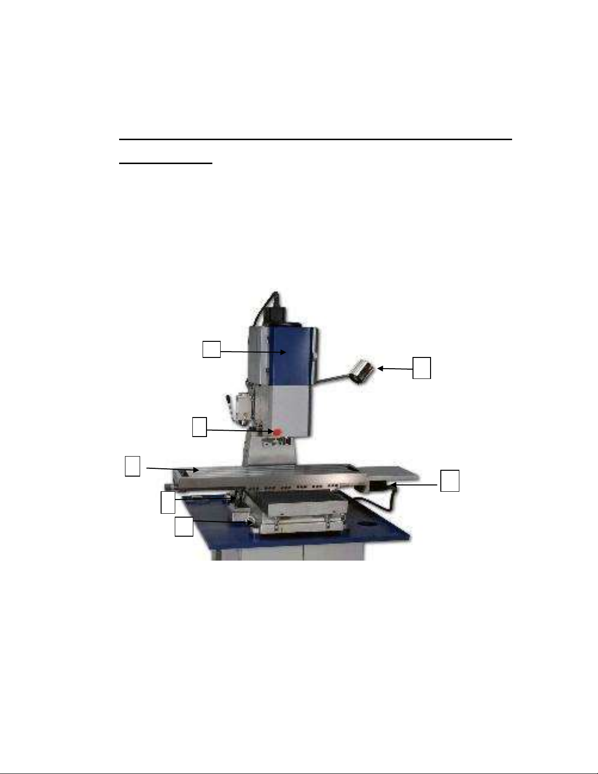
Chapter 5
MECHANICAL COMPONENT IDENTIFICATION AND
FUNCTIONS
OVERVIEW
This chapter will help you familiarize yourself with the major mechanical components and
functions of your machine.
1. Drawbar –The drawbar supports and draws tooling into the R-8 spindle of the NM-200 Bed Mill.
The function of the drawbar is to locate the tool holder accurately in relationship to the main
spindle taper. The clamping and unclamping of the tools is achieved by the manual actuation of
the drawbar system (this is not visible from the picture).
2
3
5
6
7
8
9

2. Work Light –The work light is controlled by the machine system. Please note this is an on/off
function only.
3. Emergency Stop Button –Located at the bottom left side of the mill head. Press this button to
stop movement of the slides and the mill spindle.
4. Gib Adjustment Screws –The NM-200 has a series of gib adjustment screws along the operator
side of the saddle. These screws press a metal plate (the gib) to the ways of the saddle,
increasing the tension when moving the cross-slide assembly. Before adjusting the gibs, make
sure they are well lubricated to achieve the desire result.
5. X Axis Stepper Motor –The NM-200 mill is equipped with X, Y and Z axes stepper motors. This X
axis stepper motor provides power for table movement along the X axis. See the machine
specifications for motor sizes.
6. Lifting Eye Hooks –There are two lifting eye hooks located on the operator’s side of the
machine. Use these eye hooks in conjunction with a chain or tow ropes to help move your
machine from the shipping pallet to a stand.
7. Saddle –the mill table is supported by the saddle along the Y axis.
8. Mill Table –the mill table supports your work piece and work holding devices. It travels along
the X & Y axes via ball screws. Both the NM-200 Mill has 5/8” T-slots.
9. Motor Cover –The motor is protected by a sheet metal cover. The motor is easily accessible by
turning the knurled knob on the right side of the cover. This cover should remain closed while
the machine is in operation.
10. Spindle Drive Motor –The fan cooled spindle drive motor is located behind the motor cover.
11. Compressed Nitrogen Gas Cylinder –The NM-200 mill uses a counter balance cylinder to
counter the weight of the Z axis assembly.
12. Drive Belt –The drive belt for the motor is located behind the motor cover. The motor cover
must be removed to replace or tension the belt. (Not visible in diagram)

13. Head Rotation Lock Bolts –There are two bolts, one on either side of the mill head that when
loosened, allow the operator to rotate the mill head between 0 and 90 degrees in either
direction.
14. Spindle with R-8 nose taper –The NM-200 utilizes a spindle with an R-8 taper nose for
supporting and locating work holding tools. Any standard tool holding equivalent to the R-8
specifications can be mounted on the spindle with suitable adaptors.
15. Bellows –The Y axis ball screw is protected from chips and coolant by industrial bellows.
16. Mounting Points –There are six mounting points on the NM-200 Bed Mill. The mounting points
are M10 holes located at each corner of the machine and one in the middle of each side of the
machine. Make sure that your machine is properly mounted before operating it.
17. Proximity Switches –A switch is located on each axis of travel. These switches are the
mechanical end position limits and they also are used to home the slides.
10
11
12
13
14
15
16
21
20
17

18. Proximity Switch Covers –The proximity switches on the NM-200 Bed Mill are protected from
coolant and chips with removable sheet metal cover.
19. Bed & Column –The bed and the column are a box type construction made of high quality grade
25 cast iron. They are designed for high rigidity with suitable cross section and ribs for
reinforcement. Proper casting treatment is give to relieve the castings of any undue stress
before assembly and machining is done. The X axis, Y axis and Z axis slide components including
the headstock assembly and table are mounted on the same base and column structure.
20. Lifting Point –This lifting point is used in conjunction with the lifting eyehooks. Run an
adequately sized bar through this point and attach tow ropes or chains to the bar to assist in the
mechanical lifting process.
21. One Shot Lubrication System –The one shot or single stroke lubrication system is located on
the left side of the machine. The dovetail ways, ball nuts and liner bearings are provided, a
minimum of two pumps is recommended and it is also advisable to visually check the lubrication
delivery on the lubed surfaces. Lubrication is very important for machine tools since it greatly
affects machine life. Use only recommended lubrication oils which are clean and free from
foreign matter. Follow the maintenance scheduled in this manual.
22. Bearing Guide Way System –The mill head travels along the Z axis which is equipped with the
linear bearing guide way system.
23. Lubrication Distribution Block –The shield metal lines of the lubrication system intersect at this
block to deliver lubrication to the various parts of your NM-200 Bed Mill.
24. Z axis Stepper Motor –This motor drives the Z axis of the machine and provides motion of the
head along the Z axis linear guide way.
25. Variable Frequency Drive –this is the drive for the main spindle motor.
26. Junction Box –The control system is connected to the machine via this junction box.
27. Y axis Stepper Motor –This motor drives the table along the dovetail ways of the Y axis.

Figure 5.3: NM-200 Back View
24
25
26
27

Chapter 6
MECHANICAL MAINTENANCE
6.1 MAINTENANCE SCHEDULE
Maintaining your machine as per schedule documented in this manual will help prolong the life
of the machine and aid in the production of precision work pieces. It should be noted that the
maintenance schedules listed herein, are intended to be used as a guide. The environment and
working conditions of your shop should be taken into consideration.
Daily Maintenance
Perform these maintenance tasks at the beginning and at the end of work.
AREA OF MAINTENANCE
MAINTENANCE TASK
HOW OFTEN
Lubrication System
•Check for oil level
•Pressure build up
during hand pumping
•Check for distribution
film of oil on all sliding
surfaces
•Check for leaks
At the start of work
Cutting Tools & Tool Holders
•Tighten the drawbar
•Tighten work holding
devices
At the start of work
Coolant Level (optional)
•Check for level
At the start of work
Machine Work Area
•Check for leakage and
cleanliness
At the start & end of
work
Cleaning
•Clean the work holding
devices
•Clean guards
•Clean machine
•Clean trays
At the start & end of
work
Table of contents
Popular Power Tools manuals by other brands

Craftsman
Craftsman 315.174710 owner's manual

Craftsman
Craftsman 113.213853 owner's manual

Makita
Makita TM3010CX6 instruction manual

Feider Machines
Feider Machines FMT360 Translation of the original instruction manual

Nordson
Nordson DuraBlue II User's product manual

Hitachi
Hitachi H 65SD2 Handling instructions

Makita
Makita DFL300F instruction manual

Black & Decker
Black & Decker LINEFINDER JS680V instruction manual

Parkside
Parkside AIR STAPLER SET - 2 Operation and safety notes

Baukraft
Baukraft BK-AGCDL1 Original instruction manual

Makita
Makita XWT09 instruction manual

Palmgren
Palmgren 80110B Operating manual & parts list


