Novametrix Medical Systems TIDAL WAVE SP 710 User manual
Novametrix Medical Systems Inc.
PO Box 690
5 Technology Drive
Wallingford, Connecticut, U.S.A. 06492
HANDHELD
CAPNOGRAPH/OXIMETER
User’s Manual
Model 710/715
October 12, 2000
Catalog No. 9110-23-05 / 9146-23-05


Rev. 05 TIDAL WAVE Sp User’s Manual iii
Revision History
30-Oct-98 Release, Rev. 00
15-Dec-98 Revision 01, R-N626
27-Jan-99 Revision 02
10-Dec-99 Revision 03, R-N719
6-Apr-00 Revision 04, R-N746
12-Oct-00 Revision 05, R-N835
Declaration of Conformity with European Union Directives
The authorized representative for Novametrix Equipment is:
European Compliance Services Limited
Oakdene House
Oak Road
Watchfield
Swindon, Wilts SN6 8TD
UK
Novametrix manufacturing facility is certified to ISO 9001 and EN46001 (MDD93/42/EEC Annex II). Novametrix
Medical Systems Inc. products bear the “CE 0086” mark. The product is certified by Underwriter’s Laboratories (UL)
to bear the UL mark; and tested by TUV Rheinland to IEC601-1 / EN60601-1.
TIDALWAVESp and CAPNOSTAT are registeredtrademarksandY-Sensor,SuperBright and OxySnap aretrademarks
of Novametrix Medical Systems Inc. Velcro is a registered trademark of Velcro USA, Inc. Cidex is a trademark of
Arbook, Inc. Nafion is a registered trademark of Dow Corning Corp. Models 710 and 715 are Year 2000 compliant.
Copyright 1998-2000 NovametrixMedical Systems Inc. This document contains information which is proprietary and
the property of Novametrix Medical Systems Inc., and may not be reproduced, stored in a retrieval system, translated,
transcribed or transmitted in any form, or by any means, without prior explicit written permission from Novametrix
Medical Systems Inc.

iv TIDAL WAVE Sp User’s Manual Rev. 05

Rev. 05 TIDAL WAVE Sp User’s Manual v
Contents
General Description .....................................................................................................1
Indication for use .........................................................................................................1
Keypanel Controls and Indicators ...............................................................................1
Connections and Labeling ..........................................................................................4
Principle of operation ..................................................................................................5
Safety .............................................................................................................................7
Preparation for Use ......................................................................................................9
AC/Battery Operation ..................................................................................................9
Battery Status and Alerts ............................................................................................9
Battery Use and Options ...........................................................................................10
Configuration Menus .................................................................................................16
Sensors and Patient Connections ............................................................................21
Adapter Types Available ..........................................................................................21
Setting Adapter Type ................................................................................................21
Adapter Zero Procedure ............................................................................................22
CAPNOSTAT CO2 Sensor and Airway Adapter Setup .............................................24
SpO2Sensors ..........................................................................................................27
Monitoring ...................................................................................................................41
Display of Data ..........................................................................................................41
Monitoring Mode .......................................................................................................41
Screen Displays ........................................................................................................42
Messages ..................................................................................................................44
Alerts .........................................................................................................................47
Setting Alert Limits ....................................................................................................47
Alert Audio .................................................................................................................49
Capnogram Sample Waveforms and Interpretations ................................................50
Reference Handbooks ..............................................................................................51
Printing and RS232 Options ......................................................................................53
Power and RS232 Serial Port Communications .......................................................53
Printing ......................................................................................................................54
Interpreting Printer Output .........................................................................................57
Maintenance ................................................................................................................61
Cleaning and Sterilization .........................................................................................61
Battery Maintenance .................................................................................................63
Maintenance Schedules ............................................................................................64
Specifications .............................................................................................................65
General .....................................................................................................................65
Capnograph ..............................................................................................................65
SpO2 Section ............................................................................................................66
Pulse Rate Section ....................................................................................................66
Monitor Specifications ...............................................................................................67
Additional Features ...................................................................................................67
Accessories ................................................................................................................69


Rev. 05 TIDAL WAVE Sp User’s Manual 1
Section 1 General Description
Indication for use
The Model 710 and Model 715 TIDAL WAVE Sp handheld, portable Capnometer/Oximeters are intended
to be used for monitoring end tidal CO2, respiration rate, functional oxygen saturation and pulse rate in
monitoring environments such as ventilatory support, emergency and anesthesia. The Model 715
incorporates a miniature vacuum pump to draw expired respiratory gases through the CAPNOSTAT CO2
Sensor using a sampling airway adapter and nasal cannula. TIDAL WAVE Sp is designed to monitor adult,
pediatric and neonatal patients. TIDAL WAVE Sp is not intended for any other purpose.
Keypanel Controls and Indicators
Controls
Power Key
Switches power on/off. Press the POWER key to place the unit into operate mode (ON) or to turn the unit
OFF. Refer to “AC/Battery Operation”on page 9.
With monitor ON, press and hold the POWER key to enter the MONITORING MODE selection menu.
Refer to “Monitoring Mode”on page 41 for more information.
NOTE
Components of this product and its associated accessories which have patient contact are
free of latex.
Power key
Page key
Backlight key
Battery charge indicator
Alert key
Adapter key
AC indicator
Display screen
and LED Alert LED

Section 1 Keypanel Controls and Indicators
2TIDAL WAVE Sp User’s Manual Rev. 05
Page Key
Press to set display screen to Data Display, EtCO2waveform, plethysmogram, EtCO2trend, Respiration
trend or SpO2trend.
Press and hold to enter the PRINT SELECTION menu. See “Printing”on page 54.
Alert Key
When pressed, will set the 2 minute silence (audible alerts muted for two minutes) and displays the SET
ALERTS menu. If the SET ALERTS menu is not needed, it will automatically disappear after 3 seconds.
For 2 minute silence, the icon will illuminate for the duration. Press again to cancel.
Pressand holdfor 3seconds to disableaudible alerts, andthe icon willflash.Press andholdagain tocancel.
The Alert Key LED will display the following:
•Steady yellow: audio silenced for 2 min., no alert in progress.
•Flashing yellow: audio silenced (no alert in progress).
•Flashing red and yellow: alert in progress; audio is off or 2 minute silence.
Audible alerts may be permanently disabled from the Configuration menu. Refer to “Configuration
Menus”on page 16 for more information.
Adapter Key
Press to set adapter type: adult, neonatal or sampling.
Pressandholdfor4secondstozeroan adapter.See“AdapterZeroProcedure”onpage22formoreinformation.
Press to cancel Auto Power Off function.
Backlight Key
Press to turn backlight on/off, or press and hold to adjust contrast for up/down viewing angles and for
adjustment due to extreme temperature variations.
Indicators
Battery Alert Indicator
Illuminates when the unit is on battery power. Green; battery is fully charged, slow flashing yellow;
battery power is low (approximately 20 minutes of operation remains), Fast flashing red; battery is
exhausted (approximately 5 minutes of operation remains). The battery alert indicator is off when
external power is connected. Refer to “AC/Battery Operation”on page 9 for information on connecting
AC power and charging the battery.
AC Power Indicator
Illuminated green when the monitor is connected to an AC power source (e.g. the external power supply
(PN 9220-10), or the BaseStation (PN 6998-00), while powered by the external power supply).

Keypanel Controls and Indicators General Description
Rev. 05 TIDAL WAVE Sp User’s Manual 3
Icons
The icons listed below may appear on the display screen when the TIDAL WAVE Sp is in use.
Alert Silence Icon
Audible alerts silenced.
2-Minute Silence Icon
Audible alert silenced for two minutes.
Alert Limits Disabled Icon
Alert limits disabled. Select ENABLED or DISABLED in the CONFIGURATION menu.
Airway Adapter Icon
Indicates adapter key.
Time/Date Icon
Set time/date. Press from the CONFIGURATION menu to set time and date.
Backlight Icon
Indicates backlight key.
Trend Screen Icon
Displayed beside any Trend screen.
Temperature Icon
Sensor not up to temperature icon. Displayed when performing an adapter zero and the sensor is not at
operating temperature.
Waveform Icon
CO2detected icon. Displayed when selecting an adapter zero and the monitor detects breaths.
Heart Icon
Pulse detected icon. Displayed when SpO2sensor is attached to patient and the monitor detects a pulse.
Lung Icon
Breaths detected icon. Displayed when CAPNOSTAT CO2sensor is attached to patient and breaths are detected.
Section 1 Connections and Labeling
4TIDAL WAVE Sp User’s Manual Rev. 05
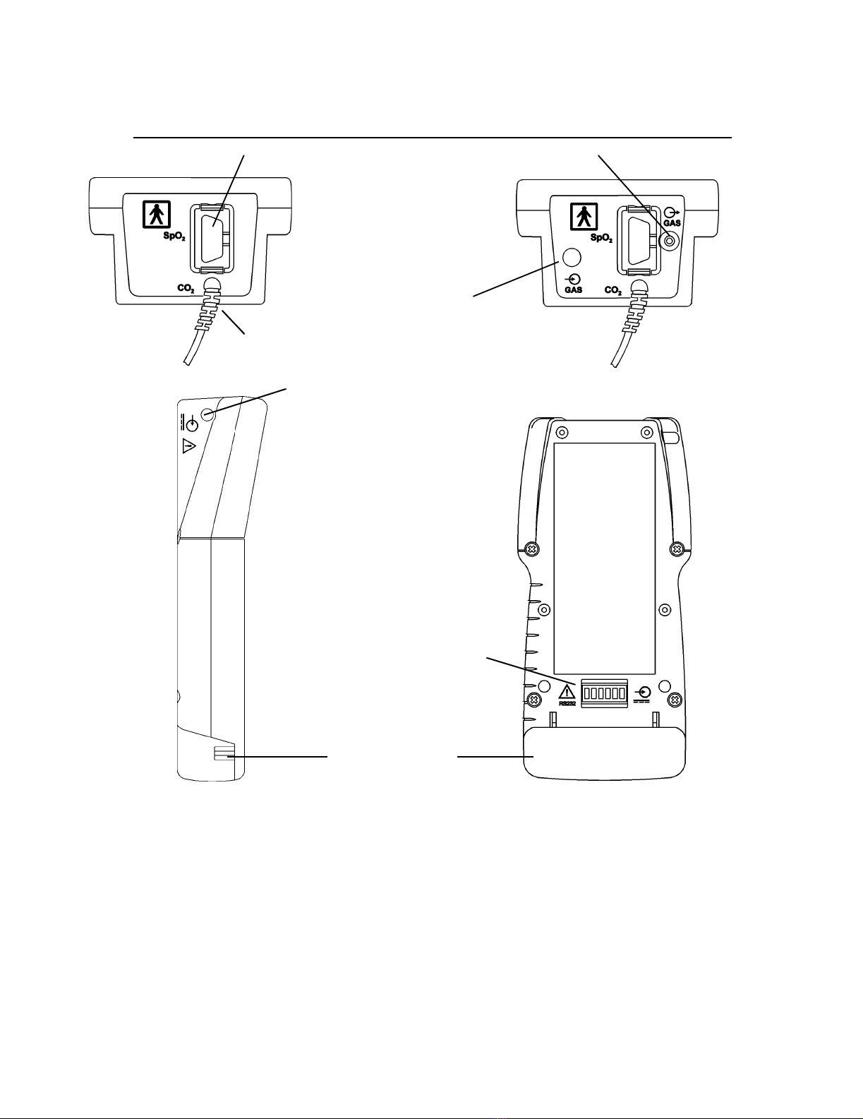
Connections and Labeling
DB-9 SpO2sensor connection
CO2sensor connection
Sampling system input
Sampling system output
Endview Endview
Model 715
Model 710
Rearview
Model 710/715
RS232 connection
DC input
Battery compartment
Sideview
Model 710/715
and external power
input from BaseStation

Principle of operation General Description
Rev. 05 TIDAL WAVE Sp User’s Manual 5
Symbols
Principle of operation
CO2
TIDAL WAVE Spuses the CAPNOSTAT CO2sensor to measure CO2by using the infrared absorbtion technique,
which has endured and evolved in the clinical setting for over two decades and remains the most popular and
versatile technique today.
The principle is based on the fact that CO2molecules absorb infrared (IR) light energy of specific wavelengths,
with the amount of energy absorbed being directly related to the CO2concentration. When an IR beam is passed
through a gas sample containing CO2, the electronic signal from the photodetector(which measures the remaining
light energy) can be obtained. This signal is then compared to the energy of the IR source and calibrated to
accurately reflect CO2concentration in the sample. To calibrate, the photodetector’s response to a known
concentration of CO2is stored at the factory in the monitor’s memory. A reference channel accounts for optical
changes in the sensor, allowing the system to remain in calibration without user intervention.
SpO2
The TIDAL WAVE Sp determines oxygen saturation using sensors that contain red and infrared (660 and 940
nanometer) light sources, called lightemitting diodes (LEDs). The light energy from each LED is beamed through
a tissue sample—a pulsating vascular bed such as the patient’s finger or toe. The remaining light energy not
absorbed by the tissue sample reaches a photodiode light receptor in the sensor. Oxygen saturated blood absorbs
Patient isolation: Identifies connection as type BF
Attention: Consult manual for detailed information
Sampling System: Gas output
Sampling System: Gas input
DC input. Connect external power supply to this port. Use only Novametrix external power
supply, Catalogue number 9220-10.
Recyclable item. This symbol is found on the internal battery and should not concern the
common user. Refer to qualified service personnel when battery replacement is required.
Separate collection. Appropriate steps must be taken to ensure that spent batteries are
collected separately when disposed of. This symbol is found on the internal battery and
should not concern the common user. Refer to qualified service personnel when battery
replacement is required.

Section 1 Principle of operation
6TIDAL WAVE Sp User’s Manual Rev. 05
different amounts of light at each wavelength as compared to desaturated blood. Therefore, the amount
of light absorbed by the blood in each pulse can be used to calculate oxygen saturation.
The TIDAL WAVE Sp is calibrated to display “functional”saturation. This differs from the “fractional”
saturation value displayed by most co-oximeters. Functional saturation is defined as:
This can be considered to represent the amount of oxyhemoglobin as a percentage of the hemoglobin that
can be oxygenated. Dysfunctional hemoglobins (COHb and METHb) are not included in the
measurement of functional saturation.
Pulse Rate is calculated by measuring the time interval between peaks of the infrared light waveform.
The inverse of this measurement is displayed as pulse rate.
The oxygen saturation and pulse rate values are updated once each second. Presence of a pulse is
indicated visibly by a plethysmogram graphic display and audibly by a “beep,”when configured.
The TIDAL WAVE Sp must be used in conjunction with SuperBright™Sensors. See “Accessories”on
page 69 for a list of available sensors and accessories.
Functional Saturation = HbO2
100 - (COHb + METHb)
HbO2 = Fractional Oxyhemoglobin
COHb = Carboxyhemoglobin
METHb = Methemoglobin

Rev. 05 TIDAL WAVE Sp User’s Manual 7
Section 2 Safety
For maximum patient and operator safety, you must follow the following warnings and cautions.
•Explosion Hazard: DO NOT use TIDAL WAVE Sp in the presence of flammable anesthetics. Use
of this instrument in such an environment may present an explosion hazard.
•Electrical Shock Hazard: Always turn TIDAL WAVE Sp off and remove any external devices
before cleaning it. Refer servicing to qualified service personnel.
•Failure of Operation: If the monitor fails to respond as described, do not use it until the situation
has been corrected by qualified personnel.
•Do not operate TIDAL WAVE Sp if it appears to have been dropped or damaged.
•Do not operate TIDAL WAVE Sp or its accessories when it is wet due to spills or condensation.
•Never sterilize or immerse the monitor, sensor or accessories in liquids.
•The monitor does not alert for NO RESPIRATION if the airway adapter is removed from the
CAPNOSTAT CO2sensor.
•Verify the “No Resp Timer”setting prior to use.
•Do not position any sensor cable in a way that may cause entanglement or strangulation.
•The TIDAL WAVE Sp is not intended to be used as a primary diagnostic apnea monitor and/or
recording device.
•Patient Safety: Care should be exercised to assure continued peripheral perfusion distal to the
SpO2sensor site after application.
•Inspect the SpO2sensor site often for adequate circulation - at least once every four hours. When
applying sensors take note of patient’s physiological condition. For example, burn patients may
exhibit more sensitivity to heat and pressure and therefore additional consideration such as more
frequent site checks may be appropriate.
•Data Validity: As with all pulse oximeters, inaccurate SpO2and Pulse Rate values maybe caused by:
- Incorrect application or use of sensor;
- Significant levels of dysfunctional hemoglobin; carboxyhemoglobin or methemoglobin;
- Significant levels of indocyanine green, methylene blue, or other intravascular dyes;
- Exposure to excessive illumination such as surgical lamps-especially those with a
xenon light source, or direct sunlight;
- Excessive patient movement;
- Venous pulsations;
- Electrosurgical interference.
•The external battery charger should NOT be used to recharge the battery nearor in close proximity
to patients and/or other medical equipment in operation. It is intended for use in service areas only
(i.e. nurses station, biomed lab, etc.).
WARNINGS
Indicates a potentially harmful condition that can lead to personal injury.
!

Section 2
8TIDAL WAVE Sp User’s Manual Rev. 05
•Connection of an external device (e.g. printer or computer) to the RS232 serial port on the
BaseStation may compromise patient safety.
•Federal (U.S.A.) law restricts this device to sale, distribution, or use by or on the order of a
licensed medical practitioner.
•Use only an external power supply approved by Novametrix for use with this device. Use of any
other power supply may damage the TIDAL WAVE Sp and void the warranty.
•Do not operate TIDAL WAVE Sp or its accessories when it is wet due to spills or condensation.
•Do not operate TIDAL WAVE Sp if it appears to have been dropped or damaged.
•Keep TIDAL WAVE Sp and its accessories clean.
•Inspect the integrity of the TIDAL WAVE Sp and its accessories prior to use.
•Never sterilize or immerse the monitor, sensor or accessories in liquids.
•Do not sterilize or immerse sensors except as directed in this manual.
•Do not apply excessive tension to any sensor cable or pneumatic tubing.
•Do not store the monitor or sensors at temperatures less than 14°F (-10°C) or above 131°F (55°C).
•Do not operate the monitor or sensors at temperatures below 50°F (10°C) or above 104°F (40°C).
•If a Single Patient Use Sampling Adapter becomes occluded, replace and discard the adapter.
•It is recommended that the CAPNOSTAT CO2sensor be removed from the circuit whenever an
aerosolized medication is delivered. This is due to the increased viscosity of the medications
which may contaminate the sensor windows, causing the sensor to fail prematurely.
•Where electromagnetic devices (i.e. electrocautery) are used, patient monitoring may be
interrupted due to electromagnetic interference. Electromagnetic fields up to 3V/m will not
adversely affect system performance.
•Refer servicing to qualified personnel.
•The TIDAL WAVE Sp monitor is intended for operation with Novametrix Single Patient Use
airway adapters.
•Operating the TIDAL WAVE Sp below 50°F (10°C) will result in longer warm-up time and reduce
battery life.
•Components of this product and its associated accessories which have patient contact are free of
latex.
•Certain rebreathing circuits, or the presence of artifacts such as cardiogenic oscillations, may
cause TIDAL WAVE Sp to react to non-respiratory CO2fluctuations as if they were breaths. This
condition affects only the RESP numerical displays; the capnogram display continues to provide
an accurate picture of the CO2waveform.
•After the life cycle of our equipment and all accessories has been met, disposal of the equipment
should be accomplished following the national requirements. Contact the local Novametrix
representative for questions concerning disposal.
CAUTIONS
Indicates a condition that may lead to equipment damage or malfunction.
NOTES
Indicates points of particular interest or emphasis for more efficient or convenient operation.
!

Rev. 05 TIDAL WAVE Sp User’s Manual 9
Section 3 Preparation for Use
The TIDAL WAVE Sp can be powered four ways: from seven “AA”disposable lithium batteries, a
rechargeable NiMH battery, the 9220-10 external power supply or the 6998-00 BaseStation combined
with the external power supply, all available from Novametrix.
AC/Battery Operation
Press the POWER key to place the unit into operate mode (ON) or to turn the unit OFF. The status
of the unit is dependent upon both the Power key and the power source.
The monitor can operate for up to 4.5 hours while powered from a fully charged internal battery (4 hours
when using sampling pump, Model 715). The battery is charging when the monitor is powered through
its DC input and the keypanel icon is green. The battery will charge even if the monitor is off. Power
to the DC input is supplied by the external power supply (Cat. No. 9220-10) with or without the optional
BaseStation (Cat. No. 6998-00).
Rechargeable and disposable battery capacity is shown in the table titled, “Battery Life and Recharge
Times”on page 14. Times may be reduced in colder temperatures or with the sampling adapter; operation
with the backlight off may slightly increase these times.
Battery Status and Alerts
When the monitor is operating on battery power, and the battery is sufficiently charged, the battery icon
LED on the keypanel will be green. The battery level is reflected on the battery icon by different
colors (for example, battery fully charged: green, battery low: flashing yellow).
The LED on the keypanel flashes red when the monitor is powered by its internal battery and
approximately 5 minutes remain. The monitor will sound an audible alert, then when the battery is depleted,
turn itself off. This alert can only be silenced by connecting the external supply or turning the monitor off.
The NiMH battery pack should be replaced, or the TIDAL WAVE Sp BaseStation (Cat. No. 6998-00) or
external power supply (Cat. No. 9220-10) should be connected to recharge the battery (rechargeable
batteries only) and power the monitor. See “Battery Life and Recharge Times”on page 14.
NOTE
When the battery is low (red blinking battery LED on keypanel) the monitor has shut
down CO2and SpO2functions. Connect to AC power as soon as possible.

Section 3 Battery Use and Options
10 TIDAL WAVE Sp User’s Manual Rev. 05
Battery Use and Options
Removing and Installing the Battery
Grasp the finger grips on each end of the battery cover. Squeeze together and pull so that the cover opens
to reveal the internal battery (the cover is hinged on the bottom of the case). Remove the battery from the
monitor.
The battery is keyed so that it can be installed in only one way (see illustration inside battery
compartment). The contacts should go in first and be located toward the top left of the monitor when
inserting. Make certain the battery cover is properly closed before operating the monitor.
NOTE
• The battery life indicator may not reflect the true battery status upon power-up for
approximately 30 seconds.
• The battery life indicator is inactive when the monitor is powered by the BaseStation or
the external power supply.
Power jack
Hinged side Battery cover
Finger grip
Interface connector
WARNING: Do NOT connect to any device not
approved by Novametrix

Battery Use and Options Preparation for Use
Rev. 05 TIDAL WAVE Sp User’s Manual 11
Rechargeable Batteries
The NiMH rechargeable battery pack (Cat. No. 400043) can be used to power the TIDAL WAVE Sp for
approximately 4.5 hours of continuous operation (4 hours when using sampling pump, Model 715).
To charge a rechargeable battery while in the monitor:
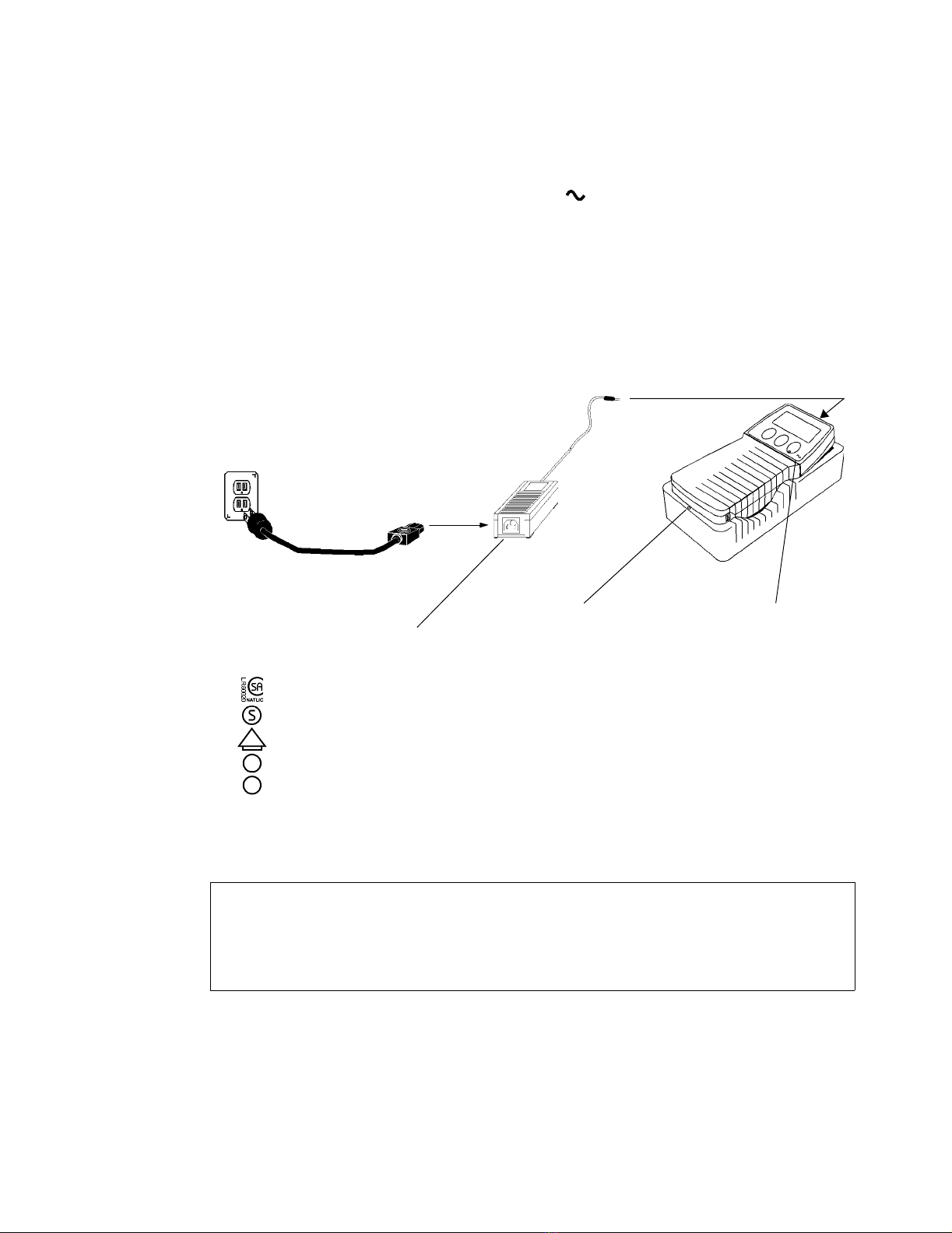
External Power Supply
Alternatively, plug the external power supply directly into the DC power jack on the side of the monitor,
and connect a hospital-grade line cord to an AC source. The AC icon will illuminate green and the
battery will charge in approximately 5.5 hours. If the monitor has been stored with the battery installed
for thirty (30) days or more, charge the battery for 24 hours prior to use.
NOTE
•Refer to the instruction sheet packaged with the rechargeable battery for complete
operating instructions.
CAUTION
•Use only Novametrix supplied devices when connecting to the power input jacks on the
TIDAL WAVE Sp or on the BaseStation.
•Do not attempt to use the adapter for the external battery charger for this function.
NOTE
•When powered by the external power supply, the TIDAL WAVE Sp will not overcharge a
rechargeable battery.
•The external power supply has a universal power input. The IEC 320 input receptacle for
line cord connection allows compatibility with every country’s voltage and frequency
requirements.
Optional
Rechargeable battery,
(NiMH 7.2 vdc)
External power supplyConnect line cord
DC input
(Cat. No. 600075) (Cat. No. 9220-10)
Section 3 Battery Use and Options
12 TIDAL WAVE Sp User’s Manual Rev. 05
Optional BaseStation
Power for the BaseStation is supplied by an external power supply (PN 9220-10) or the internal battery.
When the power supply is properly connected to the BaseStation and a monitor is placed within the
station the green, “In Use”LED will illuminate. The icon on the monitor will also illuminate
indicating that external power is connected.
Connect the external power supply jack to the monitor and connect a hospital-grade line cord from the
external power supply to an AC source.
CAUTION
•Although other connectors may physically fit, do not attempt to connect any device other
than power supplies approved by Novametrix for use with this device. Doing so may
damage the TIDAL WAVE Sp and will void the warranty.
•Never sterilize or immerse the monitor, sensor or accessories in liquids.
Monitor in BaseStationExternal power supply
Connect line cord DC input
(Cat. No. 9220-10) (BaseStation Cat. No. 6998-00)
The 9220-10 Power Supply is approved
by the following regulatory agencies:
D
FI
DVE
: Canadian Standards Assoc.
: SEMKO (Sweden)
: VDE (Germany)
: FINKO (Finland)
: DEMKO (Denmark)
illuminates indicating
a monitor is in place
and the power supply
Green “In Use”LED Illuminates indicating
external power
IEC 320 receptacle
(Cat. No. 600075)
is active

Battery Use and Options Preparation for Use
Rev. 05 TIDAL WAVE Sp User’s Manual 13
Charging NiMH Rechargeable Battery with External Charger
In a non-patient area, connect the adapter to an AC source, then plug the adapter jack into the charger.
Remove the battery from the TIDAL WAVE Sp and insert it into the external charger. The battery will be
fully charged in approximately 4.5 hours. The external charger is for use with the NiMH rechargeable
battery pack (Cat. No. 400043) only. Refer to the instructions supplied with the charger for additional
information.
WARNING
•The external battery charger should NOT be used to recharge the battery near or in close
proximity to patients and/or other medical equipment in operation. It is intended for use in
service areas only (i.e. nurses station, biomed lab, etc.).
NOTE
•With a new battery, or a battery that has not been used for 30 days or more, charge the
battery for 24 hours prior to use.
•When powered by the external power supply or the BaseStation, the TIDAL WAVE Sp will
not overcharge a rechargeable battery.
•The monitor may not operate on battery power if the battery is not sufficiently charged.
•Dispose of batteries in accordance with local laws.
NiMH Rechargeable Battery
(Cat. No. 400043)
Battery is keyed
to fit into slot in
only one direction
Connect adapter
Connect line cord

Section 3 Battery Use and Options
14 TIDAL WAVE Sp User’s Manual Rev. 05
AA Lithium Batteries
To power TIDAL WAVE Sp from AA lithium batteries, insert seven disposable batteries (Energizer L91
or equivalent) into the optional Battery Case (Cat. No. 6862-00) following the polarity markings on the
Battery Case.
Battery Life and Recharge Times
Configuring the monitor to turn off unused functions will result in longer battery life. The following table
lists battery operation times with Sampling pump off (Model 710/715), Sampling pump on (Model 715)
for each mode: CO2/SpO2, CO2, or SpO2. See “Monitoring Mode”on page 41.
WARNING
•Batteries can explode, leak or catch on fire if heated or exposed to fire or high
temperatures.
•Do not mix battery types (e.g. disposable and rechargeable AA batteries).
Configuration Power source - Approximate Monitoring Times
Rechargeable NiMH battery AA lithium batteries
Model 710/715 - CO2/SpO24.5 hours 4.0 hours
Model 715 - CO2 Sampling/SpO24.0 hours 3.5 hours
Model 710/715 - CO2only 4.5 hours 4.0 hours
Model 715 - CO2 Sampling only 4.0 hours 3.5 hours
Model 710/715 - SpO2only 7.0 hours 6.5 hours
Recharge Time:
External charger w/adapter 4.5 hours n/a
Recharge Time:
External power supply or
External power supply/BaseStation
5.5 hours (in monitor) n/a
NOTE
Excessive alerting reduces battery life when operating on battery power.
Standard
AA lithium batteries
(7 ea. - disposable)
This manual suits for next models
1
Table of contents


