BSS Audio Case Economic User manual

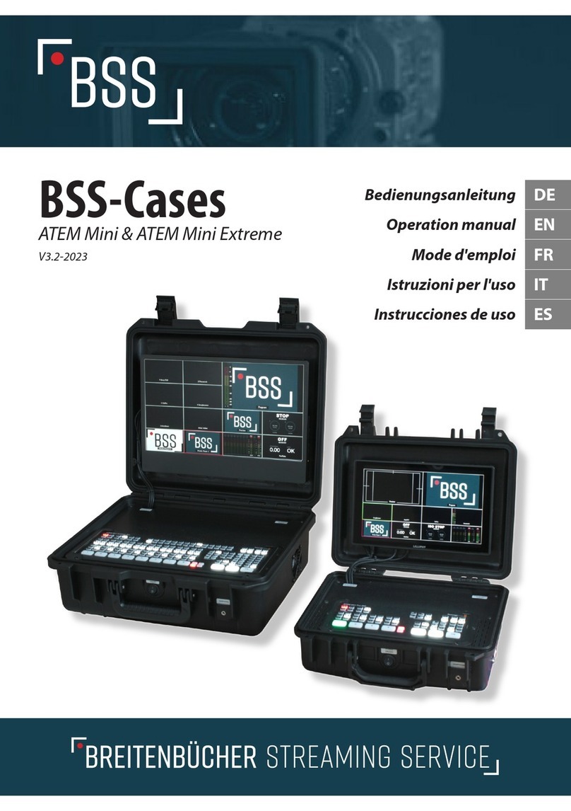
BSS-Cases
Operation manual
For ATEM Mini and ATEM Mini Extreme cases
V2.2-2022

Page 2
BSS-Streaming Service BSS-Case
BSS-Case 3
Validity 5
Safety instructions 5
Proper use 7
Connections on the BSS Case Economic 8
Einbau des Bildschirm 6
nur relevant bei BSS-Basic Case 6
Connections on the BSS Case Basic
Connections on the BSS Case Professional 15
Connections to the BSS Case Professional SDI 15
Connections BSS case options: USB / battery connection 16
Connections on the BSS Case Extreme 10
Anschlüsse am BSS-Case-Basic 10
Connections on the BSS Case Extreme Professional 11
Connections on the BSS Case Extreme Professional SDI 12
Connections BSS case options: USB / battery connection 12
Installation of the Lilliput A11-10,1“ Monitor 17
Installing the ATEM Mini / Extreme 18
Start up 21
Cooling 22
Connecting Components 23
USB charging port (option) 23
Battery connection (option) 24
3/8" mount (ATEM Mini option) 26
Monitor settings 26
Advice for use 27
Technical specications 36
Troubleshooting 36
Maintenance and service 36
Disposal 36
Page 3
Operating instruction EN DOC-000001
BSS-Case
Thank you or deciding to buy a BSS case.
We are a small manu acturer that uses practical experience to develop
products or live streaming and components or video hardware and ac‐
cessories or practical use.
We always strive to ensure that our products are o high quality and
durability which meet the user’s requirements. In addition, we are look‐
ing or the optimal balance between requirements and costs. You can
there ore choose the right technical design or your specications.
We are grate ul or your eedback on the application, improvements or
requests or our products.
Plüderhausen, April 2022
BSS-Streaming Service
Daniel Breitenbücher

Page 4
BSS-Streaming Service BSS-Case
Page 5
• Only use connection devices that are compatible with the connec‐
tion values o the ATEM Mini / Lilliput A11-10.1“ eld monitor. Fur‐
ther in ormation can be ound in the operating instructions o the re‐
spective manu acturer.
• I oreign bodies / liquids have penetrated through the ventilation
openings o the BSS case, pull out the power plug immediately and
contact our service department.
• To avoid scratches, place a so t, thin cloth between the screen and
the ATEM Mini during storage and transport.
• Store the BSS case in a dry and clean environment.
• Have the case repaired only by qualied specialists and only with
original spare parts.
• Do not use the case again i the on / o switch is de ective, the an is
not operating or any other built-in component or part is de ective.
• As long as no ATEM Mini or ATEM Mini Extreme is installed in the
case, there is a risk o tipping over due to the changed center o gra‐
vity. There ore, when opening the cover, hold the case in a horizontal
position with the help o a second person until the installation is
complete.
• Current in ormation can be ound at https://bss-streamingservice.de
/download/
Proper use
The BSS case is intended to transmit and record live streams with
proper use o the available connection options o a built-in ATEM Mini
in dry, clean and dust- ree environments. The correct position or the
case while in use is only in a lying position with the lid open.
Operating instruction EN DOC-000001
Validity
These instructions apply to the ollowing BSS case models and their op‐
tions.
Safety instructions
• Please read all instructions and illustrations prior to the initial use o
your device. Proceed accordingly. Non-observance o the operating
instructions and sa ety notes can lead to electric shock, re or seri‐
ous injuries!
• Unless otherwise stated, the instructions and sa ety in ormation ap‐
ply to both the ATEM Mini case and the ATEM Mini Extreme case.
• Only use the case lying down with its lid open and in consideration
o the ambient conditions.
• Do not use the BSS case in the rain or under the inuence o water or
humidity.
• Do not open the screwed covers or aps.
• Keep the case dry and clean.
• Do not lean on the ATEM Mini cover plate in the case.
• Avoid impact or excessive pressure on the case and its components.
• Always disconnect the case rom the power supply a ter use by rst
disconnecting the components using the on / o switch and then
pulling the power plug.
model name item number from model year
BSS-Case Economic ART-000252 03/2022
BSS-Case Basic ART-000033 05/2021
BSS-Case Pro essional ART-000129 05/2021
BSS-Case Extreme ART-000247 04/2022
BSS-Case Pro essional Extreme ART-000277 04/2022

Page 7
Connections on the BSS Case Basic
The ollowing connections on the BSS case are arranged in a user- ri‐
endly manner. Dierent connection sockets can be installed in the BSS
Case Pro essional.
Front side
• On/O switch (A)
• Headphone connection
3.5mm stereo jack (B) or opti‐
onal 6.35mm stereo jack
Right side
• Fan (C)
Left side
• Audio connections 2x3.5mm
jack stereo unbalanced (D)
• Ethernet connection socket
RJ45 (E)
• Mains connection 230V (F)
Reverse side
• • USB-C (G)
• • HDMI out (H)
• • HDMI in (I1-I4)
Operating instruction EN DOC-000001
Page 6
BSS-Streaming Service BSS-Case
Connections on the BSS Case Economic
The ollowing connections on the BSS case are arranged in a user- ri‐
endly manner. Dierent connection sockets can be installed in the BSS
Case Pro essional.
Front side
• On/O switch (A)
• Blind cover or option: head‐
phone connection 3.5mm
stereo jack (B)
Right side
• Fan (C)
Left side
• Audio connections 2x3.5mm
jack stereo unbalanced (D)
• Ethernet connection socket
RJ45 (E)
• Mains connection 230V (F)
Reverse side
• USB-C (G)
• Blind cover (H)
• HDMI in (I1-I4)
I1-I4
H
G
F
E
D
C
B
A
I1-I4
H
G
F
E
D
C
B
A

Page 9
Connections BSS case options: USB / battery connection
The connections on the BSS Case Pro essional correspond to those o the BSS
Case Pro essional with the ollowing changes.
Front side
• LED display battery opera‐
tion (M)
• 5A use (N)
Right side
• USB A (O)
• Battery connection -
XLR 4-pin (P)
OP
NM
Operating instruction EN DOC-000001
Page 8
BSS-Streaming Service BSS-Case
Connections on the BSS Case Professional
The connections on the BSS Case Pro essional correspond to those o
the BSS Case Basic with the ollowing changes.
Front side
• On/O switch (A)
• Headphone connection
6.35mm lockable stereo jack
socket (J)
Left side
• Mains connection 230V (D)
• Ethernet connection socket
RJ45 (E)
• Audio connections (2x emale
XLR-3-pin stereo unbalanced) (K1-K2)
Connections to the BSS Case Professional SDI
The connections on the BSS Case Pro essional correspond to those o
the BSS Case Pro essional with the ollowing changes.
Reverse side
• USB-C (G)
• HDMI out (H)
• HDMI in (I3-I4)
• SDI in - BNC 75Ω (L1-L2) G H L1-L2I3-I4
K1-K2 F
E
AJ

Page 11
Connections on the BSS Case Extreme Professional
The connections on the BSS Case Extreme Pro essional correspond to
those o the BSS Case Extreme with the ollowing changes.
Front side
• On/O switch (A)
• Headphone connection
6.35mm lockable stereo jack so‐
cket (J)
Right side
• Fan (C)
Left side
• Audio connectors (2x emale
XLR-3-pin stereo unbalanced)
(K1-K2)
• Ethernet connection socket
RJ45 (E)
• Mains connection 230V (F)
Revrese side
• 2x USB-C (G)
• 2x HDMI out (H)
• 8x HDMI in (I1-I8)
Operating instruction EN DOC-000001
Page 10
BSS-Streaming Service BSS-Case
Connections on the BSS Case Extreme
The ollowing connections on the BSS-Case Extreme are arranged in a
user- riendly way. Dierent connection sockets can be installed in the
BSS Case Extreme Pro essional.
Front side
• On/O switch (A)
• Headphone connection
3.5mm stereo jack (B)
Right side
• Fan (C)
Left side
• Audio connections 2x3.5mm
jack stereo unbalanced (D)
• Ethernet connection socket
RJ45 (E)
• Mains connection 230V (F)
Reverse side
• 2x USB-C (G)
• 2x HDMI out (H)
• 8x HDMI in (I1-I8)
I1-I8
H
G
F
E
D
C
BA
I1-I8
H
G
FEK1-K2
C
J
A

Page 13
Operating instruction EN DOC-000001
Page 12
BSS-Streaming Service BSS-Case
Connections on the BSS Case Extreme Professional SDI
The connections on the BSS Case Extreme Pro essional correspond to
those o the BSS Case Pro essional with the ollowing changes.
Reverse side
• 2x USB-C (G)
• 2x HDMI out (H)
• SDI in - BNC 75Ω (L5-L8)
• HDMI in (I1-I4)
Connections BSS case options: USB / battery connection
The connections on the BSS Case Extreme Pro essional with the USB /
battery connection option are the same as on the BSS Case Extreme /
Pro essional with the ollowing changes.
Front side
• LED display battery ope‐
ration (M)
• Battery connection -
XLR 4-pin (N)
Left side
• USB A (O)
• Battery connection -
XLR 4-pin (P)
G H L5-L8 I1-I4
O
P
NM
Musterfoto

Page 14
BSS-Streaming Service BSS-Case
Installation of the illiput A11-10,1“ Monitor
Only relevant for BSS-Case version “Pure”
Required tools: Allen key size 3
he cables or installing the Lilliput A11-10.1” screen are labeled and
must be plugged in according to the label on the screen. See the oper‐
ating instruction o the monitor.
Note: The cable len ths and wirin are desi ned exclusively for this monitor
and may only be used with it. Contact our service team if you want to install a
dierent monitor.
Be ore plugging in, check the lengths o the cables. These must be posi‐
tioned properly when plugged in, without being under tension.
Avoid kinks and tight bends.
Check that no cables are pinched or kinked or are placed under tension
when the cover is closed
• Cable label “HDMI in” - plug
into the monitor to“HDMI
in”
• Cable label “HDMI out” -
plug into the monitor to
“HDMI out”
• Headphone connection -
plug the angled plug on the
monitor into the“Earphone
Jack” socket, make sure that
the angled plug points to
the right when plugging in.
• Plug 12V DC, plug this into the 12V input o the monitor.
• Be ore attaching the monitor, check that all cables are properly
seated.
(Ima e 8) Place the monitor on a soft cloth
Page 15
Screw the monitor on
Tip: To avoid scratches, place a soft cloth on the cover plate of the BSS case,
then you can place the monitor there. (Ima e 8)
Have the pan head screws
M4x12 ready. Insert these rom
the outside in through the cor‐
responding holes in the cover
o the case. Place the mounting
plate on the our screws. Posi‐
tion the monitor with its as‐
tening threads congruently on
the corresponding screws in the case lid.
Tip: Only hold the monitor by the frame to avoid n erprints on the display.
Find the rst o the our astening threads with slight movements. To do
this, hold the corresponding screw against it rom the outside with the
Allen key.
Tighten all our screws rom the outside, keeping them loose at rst un‐
til they are all screwed on. Care ully retighten the screws. Max. tighten‐
ing torque 0.4 Nm (!) (Im‐
age 10)
A ter you have installed the
ATEM Mini according to the in‐
structions, test the picture and
sound o the monitor. Re er to
the monitor’s operating in‐
structions or more in orma‐
tion.
(Ima e 9) Position the monitor bracket
(Ima e 10) Screw on the monitor
Operating instruction EN DOC-000001

Page 16
BSS-Streaming Service BSS-Case
Installing the ATEM Mini / Extreme
Safety note: Before doin any work on the BSS case, pull the mains plu out of
the socket!
Do not touch the built-in electronic components when the installation slot is
open. Even when the mains plu is unplu ed, these can remain live for a
lon time and cause an electric
shock.
Risk of tippin : When installin
the ATEM Mini Extreme yourself,
there is an acute risk of tippin
over after openin the lid in its
end position. Only after installin
the ATEM Mini does the case re‐
ach the balanced center of ravi‐
ty.
Therefore, when openin the cover, hold the case in a horizontal position
with the help of a second person until the ATEM Mini Extreme has been instal‐
led.
The installation o the ATEM Mini requires technical understanding and
some manual skill. Please con‐
tact our service team i you need
assistance with the installation.
Required tools: Phillips screw‐
driver, size PH1
Plug in the cables
First remove all transport locks
and protective covers rom the (Ima e 12) Plu the cable into the ATEM
(Ima e 11) Dan er of tippin over
if ATEM Extreme is not installed
Page 17
installation recess. Use the screwdriver to remove the two C-clamps (6x
M3x8 ATEM Mini Case / 8x M3x8
ATEM Extreme Case ) that are
mounted to the le t and right o
the recess.
The ATEM Mini / Extreme is swi‐
veled into the recess provided
rom above and astened with
the enclosed C-rails. First plug in
all the cables to the ATEM Mini /
Extreme (Image 12). These are all
labeled in the same way as prin‐
ted on the ATEM Mini / Extreme. Hold the ATEM Mini / Extreme with one
hand and plug in the cables rom le t to right, starting with the micro‐
phone connectors.
Note: Never pull the cables with force, as this could dama e them.
The ATEM Mini / Extreme is inserted by swiveling the back into the re‐
cess (image 13).
Due to the large number o cables that are used at the same time, it
may be necessary to insert them one by one, twisting them slightly.
Make sure that the cables have enough space to nd their place under
the cover without much counter-pressure.
Note: Work carefully and never
force the ATEM Mini into the re‐
cess! If you feel too much back
pressure or if the cover plate de‐
forms under the pressure of the
cables, carefully remove the
ATEM Mini / Extreme and sort
the cables a ain until the ATEM
Mini / Extreme can be inserted
into the recess without too
much counter pressure. You may (Ima e 14) Screw ATEM Mini with C-
clamps
(Ima e 13) Swin in the ATEM Mini
Operating instruction EN DOC-000001

Page 18
BSS-Streaming Service BSS-Case
have to repeat this process several times until the ATEM nds its pressure-free
seat.
With the ATEM Extreme, the counter-pressure when used is correspondin ly
hi her due to the almost double number of cables. However, please also note
the above-mentioned conditions for assembly.
Place the two ATEM C-clamps on the ATEM Mini / Extreme and screw
them together using a Phillips screwdriver, size PH1, with the screws
M3x8mm (6 pcs. ATEM Mini; 8 pcs. ATEM Extreme;), max. tightening tor‐
que 0, 2Nm (! apply only slightly) (picture 14)
Start up
Turning on/o
Be ore switching on, open the
case and open the lid com‐
pletely. The BSS case has an in‐
ternal power supply unit (max.
5A). For the power supply, plug
in the supplied power cable on
the le t side o the case.
The on / o switch is located
on the ront o the case (Image 14). When it is switched on, the ATEM
Mini is switched on at the same time. The eld monitor must be started
by using the separate on / o switch on the top.
Note: Always turn o usin the on / o switch before closin the case and
then pullin the power plu ! Otherwise there is a risk of overheatin / de‐
struction of the built-in devices when the BSS case is closed while switched on.
The device is switched o by manually switching o the eld monitor at
its on / o switch on the top o the housing. Then turn o the switch on
the BSS case.
(Ima e 15) On, o switch on the
front
Page 19
Be ore closing the case, make sure that all built-in devices are switched
o. Close the case lid and remove the power cord.
Cooling
Integrated fan
The BSS case has a built-in an to cool the built-in components. It is lo‐
cated on the right-hand side o the case and must never be blocked.
Make sure that no objects penetrate through the ventilation grille and
block the an. Make sure there is enough ree space (at least 15 cm)
around the outlet opening o the an.
Vents
There are ventilation slots on
the cover plate to the right and
le t o the ATEM Mini (Image 15).
Under no circumstances may
these be covered, masked or
otherwise reduced or blocked in
their cross-section. Otherwise
there is a risk o overheating /
destruction o the built-in components.
Note: Do not expose the BSS case to direct sunli ht, otherwise there is a risk of
the components overheatin .
(Ima e 16) BSS case ventilation slots
Operating instruction EN DOC-000001

Page 20
BSS-Streaming Service BSS-Case
Connecting Components
All ATEM Mini / Extreme ports are easily accessible on the outside o the
case. In the basic version o the case, these correspond to the connecti‐
ons on the ATEM Mini and can be used in the same way. Please note the
in ormation in the section on operation with HDMI cables in the chap‐
ter.
For more in ormation, see the ATEM Mini user manual on its manu ac‐
turer's website under the Support section.
headphone jack
In addition to the inter aces o the
ATEM Mini, there is a 3.5mm
(Image 17) or a lockable 6.35mm
headphone connection (Image
18) (Pro essional version) on the
ront o the BSS case (Basic versi‐
on). The volume can be adjusted
via the eld monitor's so tware
menu. Further in ormation can be
ound in the user manual o the
eld monitor.
USB charging port (option)
With the optional USB charging connection, USB accessories can be
supplied with up to 2A charging current.
So that a device only receives the charging current it needs or optimal
charging, a ter the cables have been connected, the corresponding pa‐
rameters are rst exchanged between the device and the charging con‐
troller. I the device is purely passive, i.e. a pure consumer that cannot
send any parameters, the charge controller throttles its current to the
USB 1.0 standard o 100mA. There ore, various devices cannot be char‐
(Ima e 17) 3.5mm headphone jack
(Ima e 18) 1/4" headphone jack
Page 21
ged at all or only very slowly at
the USB charging socket. This
can also aect USB hubs, i.e.
USB distributors, which regis‐
ter with the charging control‐
ler with their own (sometimes
lower) charging parameters.
Since even USB connection cables can have chips in the meantime, the
ollowing recommendations apply or optimal charging on the BSS case
or the ATEM Mini:
• Only connect devices directly (do not use USB hubs)
• Only use original cables rom the manu acturer
• Do not connect any passive devices (illuminated mini Christmas
trees etc.)
Battery connection (option)
Never connect 230V mains volta e to the battery connection. There is dan er
to life!
Do not connect any other low vol‐
ta es than the permissible
12V-14.4V DC volta e to the bat‐
tery connection.
The battery connection on the
BSS case is used to supply the
built-in components and those
connected to the optional
charging connection. All
12-14.4V batteries/accumulators that allow a permissible continuous
load o at least 5A are suitable as a voltage source.
(Ima e 20) BSS case battery connector
(Ima e 19) BSS case USB char in socket
Operating instruction EN DOC-000001

Page 22
BSS-Streaming Service BSS-Case
Do not connect batteries that do not meet these requirements. There is a risk
of overheatin , short circuit and re.
Optionally, you can operate the case with the car adapter cable
ART-000325 via a 12V on-board power socket or the cigarette lighter.
When connecting to an on-board voltage socket, make sure that it pro‐
vides 12V/5A. Attention, on-board voltage sockets in trucks are o ten
operated with 24V!
Volta es reater than 14.4V can dama e or destroy the control electronics in
the BSS case.
The on/o switch on the ront o the housing switches both mains and
battery voltage. As long as mains voltage is present, the electronics give
priority to this. As long as there is no mains voltage, in the event o a
power ailure or when the mains plug is removed, the electronics auto‐
matically switch to battery
power. As soon as the case is
powered by battery voltage,
the red LED on the ront o the
case lights up.
Overload safety fuse
I 5A or more are constantly
consumed by the connected
devices, the overload protecti‐
on on the ront can trigger. In this case, disconnect unnecessary consu‐
mers (e.g. rom the USB charging port) rom the power supply and press
the use sa ety button back a ter a short cooling phase.
Reverse polarity protection
The built-in Case on-board electronics have reverse polarity protection.
In rare cases, it can be the case with vehicle on-board voltage sockets
that these lead to ground (-) on the pin contact instead o +12V. I , a ter
connecting the case to an on-board voltage socket, no unction o the
devices is apparent, please check this possibility as well.
(Ima e 21) LED & fuse for the battery sup‐
ply on the front
Page 23
Using the adapter cable ART-000326 with its open cable end, various
customer-specic plugs can be assembled or connection to a 12V DC
voltage source. Please note that all plugs or connecting elements used
must be approved by the manu acturer or at least 5A continuous cur‐
rent.
Pay attention to the type o attachment described by the manu acturer
in order to minimize contact resistance and ensure a sa e current ow.
Wire color at the open end: brown = +12V ; blue = ground
3/8" mount (ATEM Mini option)
The case can be attached to tripods, tubes and the like via the 3/8 inch
attachment on the bottom o the housing.
It is attached using a 3/8 inch UNC thread, which is a common type o
attachment in photo and video technology.
The minimum screw-in depth is 15mm, the maximum tightening tor‐
que (with lock nut) is 20Nm.
The maximum load values o the case when assembled can be taken
rom the ollowing sketch. These are 75N rom the vertical at the ront
and side edges.
Monitor settings
ATEM Mini Economic
ATEM Mini Basic /- Pro‐
fessional
The eld monitor in the
case or the ATEM Mini
Basic or Pro essional has
its own power switch on
(Ima e 22) Max. load: F = 75N
Operating instruction EN DOC-000001

Page 24
BSS-Streaming Service BSS-Case
the top right o the monitor. This must also be actuated a ter switching
on the main switch.
ATEM Mini Extreme
ATEM Mini's monitor is turned on and o using the main switch on the
case. All necessary menu settings can be set using buttons on the right
side o the monitor base. For advanced settings, please re er to the mo‐
nitor's operating instructions included in the scope o delivery.
The inclination o the monitor can be ergonomically adjusted to the
right viewing angle by opening it. (Image 23) To do this, hold the moni‐
tor in the middle o the upper rame and loosen it rom the two holding
magnets with a slight tug.
Before closin the case lid, return the monitor to its ori inal position. Both
ma nets must be securely contacted.
Advice for use
HDMI
Since the introduction o this
standard, HDMI cables have
been available in dierent ver‐
sions, currently up to version
2.1. These dier technically,
among other things, in the
maximum trans errable data
rate, the image resolution and
requency, the sound transmission and the color space ormats.
All HDMI cables used in the BSS Case or ATEM Mini are at least HDMI
specication 2.0 compliant. This corresponds to a maximum image re‐
(Ima e 23) Monitor detached from the ma‐
netic holder
Page 25
solution o 4k 60Hz. Since the ATEM Mini can process a maximum o
1080p 60Hz signals, there are enough reserves.
HDMI is a digital data transmission. In contrast to analog signal trans‐
missions, in which the signal gradually loses level over the length o the
transmission path, this is either available in ull quality or ails complete‐
ly. There ore, please note the ollowing in ormation or trouble- ree ope‐
ration.
What to do if no signal arrives at ATEM Mini?
ATEM Mini - dierences in HDMI inputs
The HDMI input 1 on ATEM Mini is what is known as a “low-latency” in‐
put. Use this or all HDMI connections with cable lengths over 5m or or
signals that may not be correctly received at inputs 2-4.
Reliable signal transmission with HDMI depends on several actors:
Specication and quality of HDMI cables
• Use only HDMI cables with specication 2.0 or better. These are also
commercially available under the name "HDMI Premium High
Speed".
• Use cables that are as short as possible.
• With cable lengths >5m, the shielding and the cable structure are
very important. Only use multiple (triple) shielded, high-quality ca‐
bles.
• Wherever possible, avoid cable lengths o 10m or more. Alternative‐
ly, use active signal converters on SDI, CAT5, ber optics or similar
transmission variants that allow longer cable routes due to their spe‐
cication. HDMI cables with a signal repeater can also work, but
should be tested with the signal source and receiver (ATEM Mini).
Signal source
The signal source is also crucial. Depending on the device, one cable
may work ne on one source, but the same cable on the same ATEM
Operating instruction EN DOC-000001

Page 26
BSS-Streaming Service BSS-Case
Mini HDMI input on another source may not. This depends on the signal
level provided by the source device, how high its attenuation is in com‐
bination with the cable, etc.
Our experience shows that with high-quality, well-shielded cables, even
sources that no longer deliver a signal with poor-quality cables will
work per ectly with the ATEM Mini. However, a test is necessary in ad‐
vance in any case.
Compatible parameters
Normally, active HDMI devices agree on compatible parameters in a
data exchange be ore they start transmitting. In the case o the ATEM
Mini, this means a maximum resolution o 1080p 60Hz, 8-bit color
depth, and RGB or 4:2:2 color subsampling.
However, individual devices such as (pro essional) video cameras or
(SDI) signal converters can or do output a xed, pre-parameterized si‐
gnal. I this is not compatible with the specications o the ATEM Mini
(e.g. 4k, 10-bit, REC 2020, etc.), there will be no signal or image ickering
on this input regardless o the cables used (a stable connection will not
be established ) out o !
There ore, please set the output parameters o your signal source to
match the specications o ATEM Mini's HDMI inputs.
Signal receiver
Not every receiver o an HDMI signal has the same input sensitivity. One
device can establish a secure signal connection with the appropriate
source-cable combination, another not. In our case, however, when
operating with the ATEM-Mini, this question is obsolete. Here we have
to live with what Blackmagic Design has developed and installed on
components.
Page 27
Conclusion
In all our tests with corresponding cables rom dierent manu acturers,
in dierent cable lengths (0.3 m - 10 m), on dierent sources, with die‐
rent ATEM Mini and with the corresponding HDMI test device (signal
generator), we came to the ollowing result reached:
With high-quality cables (2.0 and good 3-way shielding) and the correct,
compatible transmission parameters, all tested sources deliver signals
via the BSS case to the ATEM-Mini without any problems. We only noti‐
ced a signal ailure on the ATEM Mini with a (cheaper) cable with a
length o 10 m. It didn't matter whether the cables were plugged direct‐
ly into the BSS case or into the ATEM Mini. Alternatively, with a high-
quality 10 m HDMI cable, the signal ow with all tested sources was
possible without any problems.
Our recommendation:
Based on our consistently positive experience, we recommend using
HDMI quality cables rom PURELINK (e.g. PI 1000 series or better). These
are available in dierent lengths.
Audio connections
Depending on the version, the BSS Case or ATEM Mini contains two au‐
dio inputs, which are designed either as 3.5 mm stereo jack sockets (Ba‐
sic) or as 3-pin XLR sockets (Pro essional). These inputs are unbalanced
stereo inputs, analogous to the inputs on ATEM Mini. This can be used,
or example, to import the audio signal rom a PC or smartphone. The
pro essional case includes two audio adapters (3.5 mm stereo jack to 3-
pin XLR connector).
Unbalanced stereo inputs
The input sensitivity o the two audio inputs can also be switched to
"Mic" (microphone) in the ATEM so tware (ATEM So tware Control Pa‐
nel). Nevertheless, these inputs are not suitable or the direct connecti‐
on o a symmetrically wired microphone. In such a case, a (stereo) signal
Operating instruction EN DOC-000001

Page 28
BSS-Streaming Service BSS-Case
converter (balanced to unbalanced) must be connected upstream.
Other methods, such as using audio cables with appropriate jumpers
between the pins, can work in individual cases, but o ten result in
ground loops or other audio arti acts that do not lead to the desired re‐
sult.
Feeding the signal rom the unbalanced outputs o an upstream mixer
is certainly one o the easiest ways to connect microphones to the ATEM
Mini. Our experience shows that, depending on the internal circuitry o
the console, it may still be necessary to use a (two-channel) line trans‐
ormer to decouple ground loops.
Our recommendation:
• Wherever possible, use hi- level, unbalanced stereo signals to eed
ATEM Mini's audio inputs.
• Use an upstream mixer with unbalanced outputs to connect micro‐
phones. It may be necessary to use a Y-cable with a 3.5 mm stereo
jack ( or the basic case) or one with a 3-pin XLR male connector ( or
the pro essional case).
• Depending on the internal circuitry o the mixer, ground loops can
still occur. In this case, please use an appropriate line trans ormer
(galvanic isolation) between the mixer output and the ATEM Mini au‐
dio input.
• Alternatively, signal converters (balanced – unbalanced) can be used
to directly eed in individual symmetrical audio sources. These exter‐
nal converters are available rom specialist retailers.
Audio workaround
Many cameras can process symmetrical signals directly (usually recogni‐
zable at the XLR input). The signal is then made available to the ATEM
Mini via the HDMI input. This solution also has the advantage that video
and audio rom the camera are synchronized. In this video input, the au‐
Page 29
dio signal can be placed rmly in the stream with the“ON”button on
the ATEM Mini, even when switching sources.
For more in ormation on ATEM Mini's audio specications, please visit
the manu acturer's orum at:
https:// orum.blackmagicdesign.com
Operating instruction EN DOC-000001

Page 30
BSS-Streaming Service BSS-Case
Technical specications
Conditions for proper use
Electrical connected load
Electrical connection values battery voltage
Maximum screw tightening torques
Description Screw size Maximum torque
ATEM-Cover DIN 7380 M4x12 0,3 Nm
Screen screw connection DIN 7380 M4x12 0,4 Nm
ATEM C-clamps ISO 7380 M3x8 0,2 Nm
Supply voltage = 12 - 14,4V/5A
Power 60 W
Temperature range +5° – +40° C
Relative humidity 20 – 90% No condensation
Storage temperature -20° – +60° C
Do not use at altitudes over
2000m above sea level
Do not operate in a dusty
environment
Supply voltage ~230V/16A
Power 60 W
Page 31
Troubleshooting
Occurred error First action Further action
The built-in
components do not
work.
Check i the power plug is
plugged in properly.
Turn on the on/o
switch on the BSS case
again.
Check whether mains
voltage is present.
Plug into a dierent
outlet/circuit.
With battery operation
- the built-in
components do not
work
Check or battery voltage.
(is the LED on the ront
lit?)
Remove all connected
consumers (e.g. at the
USB port) and turn the
on/o switch on again.
The screen doesn't
work.
(ATEM Mini only)
Turn on the screen by
pressing the power
button (top right) or >5
seconds.
Check that the 12V DC
power connector on the
screen (bottom le t) is
properly plugged in.
The an is not running Switch o the BSS case,
disconnect it rom the
power supply and check
whether a oreign object
is blocking the an (visual
inspection).
Care ully remove the
oreign body rom the
outside. Otherwise
contact our service.
A connected device is
not recognized on the
ATEM Mini / Extreme.
Ensure that the
appropriate inter ace on
the device is enabled and
compatible with the
required ATEM input
values.
For HDMI input signals:
Change the HDMI input
on the BSS case and/or
swap the HDMI
connection cable.
Operating instruction EN DOC-000001

Page 33
Disposal
Electronic components do not belong in
household waste, but should be disposed o
separately.
Operating instruction EN DOC-000001
Page 32
BSS-Streaming Service BSS-Case
Maintenance and service
Every time you start up, check that the an o the BSS case is running.
Regularly check the power cord or any damage.
Keep the case clean. The sur aces can be cleaned with a damp cloth.
Note: Plastic cleaners and especially disin ectants can attack the sur ace
o the BSS case. There ore, rst test cleaning agents and disin ectants
specically approved or plastic on an inconspicuous area or changes
to the material.
You can nd in ormation on cleaning the built-in components in their
operating and commissioning instructions or on the manu acturer's
website.
Service address
In the event o service or spare parts requests, please contact the ad‐
dress below. In any case, have the 10-digit serial number o the BSS case
ready. You can nd this on the type label on the underside o the case.
BSS Streaming Service
Mühlstraße 80
D-73655 Plüderhausen
Germany
Tel: +49 (0)176/81228565
Fax: +49 (0)7181/884765

Page 35
Operating instruction EN DOC-000001
Page 34
BSS-Streaming Service BSS-Case

Technical changes reserved.
BSS Streaming Service
Mühlstraße 80
D-73655 Plüderhausen
Germany
www.bss-streamingservice.de/bss-case/
This manual suits for next models
9
Table of contents
Other BSS Audio Measuring Instrument manuals
Popular Measuring Instrument manuals by other brands

Ensure Technologies
Ensure Technologies Touch Getting started

Cannon
Cannon SimpleVIS reference guide

Kolida
Kolida Total Station KTS-462R10L manual

Quicklynks
Quicklynks T20 user manual

IFM Electronic
IFM Electronic Efector 300 SD8000 operating instructions

techem
techem Kamstrup MULTICAL 402 operating instructions

Sinowon
Sinowon VPS300 Series Operation manual

EUTECH INSTRUMENTS
EUTECH INSTRUMENTS LEAD EPOXY instruction manual

PCE Health and Fitness
PCE Health and Fitness PCE-RM 100 user manual

Hanna Instruments
Hanna Instruments HI 9219 instruction manual

Kobold
Kobold DAG-M35 Series operating instructions

PPS
PPS PPS25 user manual