NOVANEX Inova OnTime User manual

Inova OnTime®Clock
Installation and User Guide
Firmware version 1

All claims based on information publicly available at time of printing. All other product or service names mentioned
in this document may be trademarks of the companies with which they are associated.
© 2019 Novanex, Inc. | All rights reserved | page i
Inova OnTime Clock
Installation and User Guide
Firmware Version 1
December 28, 2018
Part Number: 715412
NOTICE OF TRADEMARK:
Inova OnTime is a registered trademark of Novanex, Inc.
Microsoft, Microsoft Windows, and PowerPoint are registered
trademarks of Microsoft Corporation.
While reasonable efforts have been taken in the preparation of this document to
ensure its accuracy, Novanex, Inc. assumes no liability resulting
from any errors or omissions in this manual, or
from the use of the information contained herein.
© 2019 Novanex, Inc.
1180 Seminole Trail, Suite 327
Charlottesville, VA 22901
434.509.1108
www.novanexsolutions.com

All claims based on information publicly available at time of printing. All other product or service names mentioned
in this document may be trademarks of the companies with which they are associated.
© 2019 Novanex, Inc. | All rights reserved | page ii
Table of Contents
1. OnTime Introduction....................................................................................1
1.1. Clock Identification .................................................................................2
2. Safety Instructions.......................................................................................3
3. Technical Specifications..............................................................................4
4. Installation ....................................................................................................5
4.1. Pre-Installation........................................................................................5
4.2. Unpack the Clock ...................................................................................5
4.3. Power over Ethernet Cabling Plan..........................................................5
4.3.1. Small Scale Installations ..........................................................................5
4.3.2. Sites with PoE Enabled Network Equipment............................................6
4.3.3. Sites with no Existing PoE Equipment......................................................6
4.4. Surface Mounting the Analog Clock .......................................................7
4.5. Mounting the Double Sided Analog Clock ..............................................8
4.6. Surface Mounting the Digital Clock.........................................................9
4.7. Pendant Mounting the Digital Clock –Single or Double .......................11
4.8. Cantilever Mounting the Digital Clock –Single or Double ....................12
4.9. Flush Mounting the Digital Clock ..........................................................13
4.10. Power Up and Verification.................................................................15
5. Configuration..............................................................................................17
5.1. Introduction to SNTP ............................................................................17
5.2. Introduction to the OnTime Management System ................................17
5.3. Clock Configuration ..............................................................................17
6. Using DHCP for Addressing and Configuration......................................19
6.1. DHCP Configuration.............................................................................19
6.2. DHCP Configuration Settings...............................................................19
6.3. DHCP Configuration Test and Rollout..................................................20
6.4. Creating a DHCP Configuration String .................................................20
6.5. OnTime Management Settings.............................................................22
6.6. Setting Different DHCP Option Numbers for a Clock............................22
6.7. Verifying the DHCP Configuration Settings on a Clock ........................23
6.8. DHCP Configuration Example for Microsoft Server..............................23

All claims based on information publicly available at time of printing. All other product or service names mentioned
in this document may be trademarks of the companies with which they are associated.
© 2019 Novanex, Inc. | All rights reserved | page iii
7. Telnet Configuration ..................................................................................24
7.1. Establishing a Telnet Connection to the Clock .....................................24
7.2. Configuring an IP Address....................................................................25
7.2.1. DHCP.....................................................................................................25
7.2.2. Assigned Static IPv4 Address ................................................................25
7.2.3. Auto-Configured IPv6 Address...............................................................25
8. Specifying a Time Server...........................................................................27
8.1. Setting the Time Zone ..........................................................................28
8.2. Configuring Daylight Saving Time ........................................................28
9. Troubleshooting.........................................................................................29
10. Warranty and Maintenance....................................................................31
10.1. Warranty ...........................................................................................31
10.2. Repair and Returns...........................................................................31
11. Glossary of Terms..................................................................................33
Appendix A: Clock Configuration...................................................................34
Appendix B: Configuring DHCP Options for Microsoft Servers..................39
Appendix C: Clock Management System Support.........................................41

OnTime Clock
Installation and User Guide
Firmware Version 1
All claims based on information publicly available at time of printing. All other product or service names mentioned
in this document may be trademarks of the companies with which they are associated.
© 2015 Novanex, Inc. | All rights reserved | page 1
1. OnTime Introduction
The Inova OnTime®Clock brings all the advantages of Power over Ethernet (PoE)
technology to the marketplace in a real-time synchronized system of clocks.
PoE is an exciting and relatively new technology that allows devices to get both power
and data over standard network cabling. It is the same technology that powers Voice
over Internet Protocol (VoIP) phones.
Delivering both data and power over one set of wires simplifies installation, saves
space, and eliminates the need for electrical outlets at the clock mounting locations.
Additionally, the option of centralized Uninterrupted Power Supply (UPS) backup
allows PoE devices to continue running even in the event of a power failure.
Note: The local area network must support IEEE 802.3af PoE for the OnTime Clocks to
operate.
This document contains:
•Safety Instructions
•Technical Specifications
•Installation Instructions
•Configuration Procedures
•Troubleshooting Solutions
•Maintenance/Warranty
Novanex maintains a support website for registered customers at
support.novanexsolutions.com. This website contains:
•Frequently asked questions
•Support information
•Access to the OnTime Management System that can be used to manage your
clock system

OnTime Clock
Installation and User Guide
Firmware Version 1
All claims based on information publicly available at time of printing. All other product or service names mentioned
in this document may be trademarks of the companies with which they are associated.
© 2015 Novanex, Inc. | All rights reserved | page 2
1.1. Clock Identification
This manual applies only to the firmware version 1 of the OnTime Clock, produced
from 2005 to mid-2015. Refer to the table below to determine which model you have. If
you believe that you have an OnTime Clock Firmware Version 2, please refer to the
support site for the version 2 manual.
Firmware Version 2
Firmware Version 1
Production Years
Mid-2015 to present
2005 to mid-2015
Firmware Versions
2.x
1.x
Organizationally Unique
Identifier (OUI), or MAC
Address Prefix
00-30-D1
00-60-35
Digital Clock Identification
Observe the firmware
version on a reboot or power
cycle and look for firmware
version 2.x
Observe the firmware
version on a reboot or power
cycle and look for firmware
version 1.x
Analog Identification
No LED Digits on the Rear
Look for LED Digits on the
rear, which indicate a
firmware version 1 clock

OnTime Clock
Installation and User Guide
Firmware Version 1
All claims based on information publicly available at time of printing. All other product or service names mentioned
in this document may be trademarks of the companies with which they are associated.
© 2015 Novanex, Inc. | All rights reserved | page 3
2. Safety Instructions
Read and understand all instructions before installing or operating an OnTime Clock.
This product is safe when installed and operated as described in this user guide.
•To prevent injury, damage to the unit, or other harm, read this manual in its
entirety before installing or operating the clock.
•Observe normal safety precautions and use appropriate safety equipment (safety
glasses, gloves, ladders, etc.) when installing this product.
•Never install wiring during a lightning storm.
•Never install data jacks or electrical wiring in wet locations unless the equipment
is specifically designed for that purpose.
•Be sure that mounting hardware is suitable for the mounting surface and
sufficient to support the weight of the clock.
•Observe all local codes when installing the product.
•This product is not a toy! Please keep it out of the reach of children.
•Operation of this product in a manner inconsistent with the instructions in this
manual may result in personal injury and damage to the product and will void
the warranty.
•Do not use harsh cleaners or aerosol cleaners. Use a damp cloth for cleaning.
•Do not place this product on an unstable cart, stand, or table. The product may
fall, causing injury or damage.
•This product is not approved for damp or wet locations; it is certified for dry,
indoor installation
OnTime Clock
Installation and User Guide
Firmware Version 1
All claims based on information publicly available at time of printing. All other product or service names mentioned
in this document may be trademarks of the companies with which they are associated.
© 2015 Novanex, Inc. | All rights reserved | page 4
3. Technical Specifications
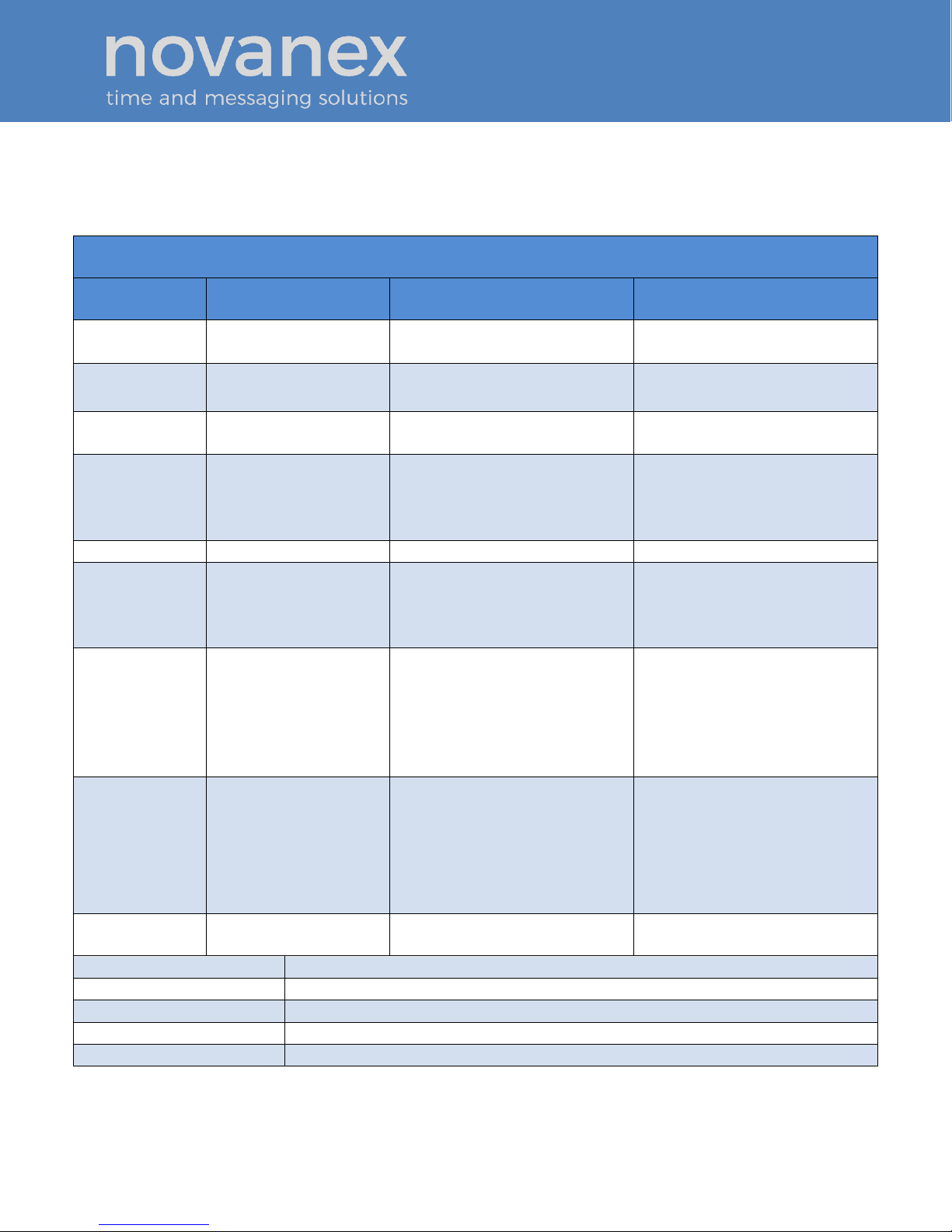
The OnTime Clock is available in three models with the specifications listed in Table 1.
Table 1: Technical Specifications
Technical Specifications
Analog
Digital (hh:mm)
Digital (hh:mm:ss)
Display Face
Analog Clock Dial
12” (30 cm)
4-Digit
Red or green 7-segment LED
6-Digit
Red or green 7-segment LED
Viewing
Distance
100 feet
150 feet
150 feet
Standard
Cabinet
Black Injection
Molded Plastic
Black Injection Molded
Plastic
Black painted Aluminum
Optional
Cabinet
Double sided
Putty or Off-White Injection
Molded Plastic, Black Painted
Aluminum, Brushed Stainless
Steel
Brushed stainless steel
Accuracy
+/- 1 Second
+0/-200 milliseconds
+0/-200 milliseconds
Power
Consumption
PoE, IEEE 802.3af
compliant
Single sided: 3W
Double sided: 4W
PoE, IEEE 802.3af compliant
8W actual consumption
PoE, IEEE 802.3af compliant
9.5W actual consumption
Dimensions
Single sided: 13.4”
diameter x 2”D
(34.3 cm x 5.1 cm)
Double sided: 13.5”
diameter x 8.5”D
(34.3 cm x 21.6 cm)
12”L x 6”H x 2.28”D
(30.5 cm x 15.2 cm x 5.8 cm)
17.5”L x 6”H x 2.28”D
(44.5 cm x 15.2 cm x 5.8 cm)
Weight
Single sided: 2 lbs
(0.9 kg)
Double sided: 7.9 lbs
(3.6 kg)
Plastic Cabinet: 1.6 lbs
(0.7 kg)
Aluminum Cabinet: 2.2 lbs
(1.0 kg)
Stainless Steel Cabinet: 4.1 lbs
(1.85 kg)
Aluminum Cabinet: 3.25 lbs
(1.47 kg)
Stainless Steel Cabinet: 5.6 lbs
(2.5 kg)
Flush Mount
Option
Not Available
Black or stainless steel
Black or stainless steel
Network Interface
10/100 BaseT
Operating Temperature
32º to 104º F (0º to 40º C)
Operating Humidity
95% maximum, non-condensing
Certifications
UL/CSA 60950-1, ETL Listed, CE Marked, RoHS Compliant
Warranty
Two (2) years, returned to factory. Refer to Section 10 for warranty details.

OnTime Clock
Installation and User Guide
Firmware Version 1
All claims based on information publicly available at time of printing. All other product or service names mentioned
in this document may be trademarks of the companies with which they are associated.
© 2015 Novanex, Inc. | All rights reserved | page 5
4. Installation
4.1. Pre-Installation
Before installing any display, you should:
•Obtain all necessary permissions from facilities managers or property owners.
•Develop a LAN diagram showing the desired location of each display unit.
•Plan the Power over Ethernet (PoE) power solution.
•Select a mounting method for the clock.
•Acquire tools and materials including assorted screwdrivers, power drill, and
other materials necessary to ensure that mounting brackets are installed in
compliance with building codes and restrictions.
4.2. Unpack the Clock
When the clock shipment arrives, inspect all packing boxes for damage. Unpack all
clocks and inspect them so that you can report any damage to Novanex.
4.3. Power over Ethernet Cabling Plan
The OnTime Clocks require connection to PoE enabled network equipment that can
source power in compliance with IEEE 802.3af. PoE power is commonly used to power
devices such as wireless Access Points and IP telephones; it is usually injected into the
LAN using either PoE enabled Ethernet switches or Mid Span power injectors. Consult
with your IT Group to make sure that the required PoE equipment is in place.
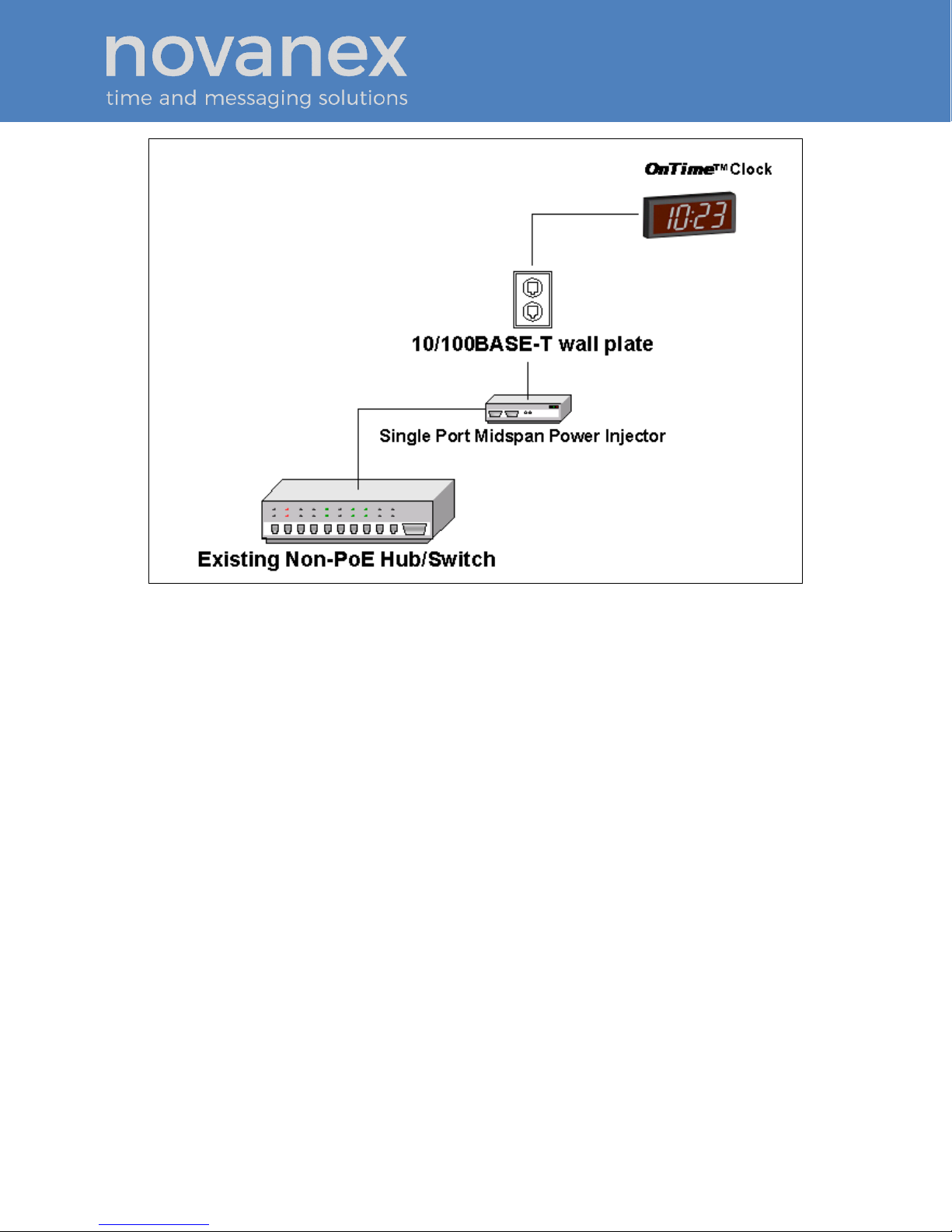
4.3.1. Small Scale Installations
Single port PoE power injectors are the best means of powering PoE devices for a
demonstration system or a small scale deployment. Novanex offers a single port PoE
injector for sale to support these systems (see Figure 1). Refer to OnTime Store for more
information on this part.
A power injector is typically installed in the communications room, and passes Ethernet
communications through while also injecting power in accordance with the IEEE
802.3af standard. The 48 VDC power is only supplied to devices that request it through
a handshake mechanism, so normal Ethernet devices are not damaged if connected to a
standard PoE port. Note that a power injector requires a connection to AC power, and
may be connected to a battery backed uninterruptable power supply (UPS).
OnTime Clock
Installation and User Guide
Firmware Version 1
All claims based on information publicly available at time of printing. All other product or service names mentioned
in this document may be trademarks of the companies with which they are associated.
© 2015 Novanex, Inc. | All rights reserved | page 6
Figure 1: PoE Cabling Plan
4.3.2. Sites with PoE Enabled Network Equipment
Sites that are already equipped with PoE enabled network equipment are most likely
already compatible with the OnTime Clock. The OnTime Clock will automatically
request and receive power from a PoE enabled switch that conforms to the IEEE 802.3af
standard.
If the site plan calls for a significant number of clocks to be powered from a single piece
of network equipment, it may be useful to verify that that piece of equipment can
deliver the necessary power. Some PoE enabled switches cannot deliver the full IEEE
802.3af power of 15.4 Watts per port or may require certain power options to do so.
Refer to the specifications in Table 1 for the actual power consumption of all of the units
and to the manual for your particular PoE enabled power sourcing equipment.
4.3.3. Sites with no Existing PoE Equipment
Sites that are not currently equipped with PoE enabled network equipment are typically
best served by Midspan Power Injectors. The Midspan Power Injector is a multi-port
rack mounted device that looks a lot like an Ethernet Switch. Typically it is installed in
the rack near the existing Ethernet switch, and any ports that require PoE service are
routed through the Midspan Power Injector. These units are typically available in 6

OnTime Clock
Installation and User Guide
Firmware Version 1
All claims based on information publicly available at time of printing. All other product or service names mentioned
in this document may be trademarks of the companies with which they are associated.
© 2015 Novanex, Inc. | All rights reserved | page 7
port, 12 port, 24 port, or 48 port configurations. The OnTime Store offers a single port
PoE injector for sale to support demonstration systems. Note that Midspan Power
Injectors can also be configured for battery backup.
The OnTime Clocks require connection to a PoE enabled LAN. PoE power is usually
injected into the LAN using either PoE enabled Ethernet switches or Mid Span power
injectors. Consult with your IT Group to make sure that the required PoE equipment is
in place.
4.4. Surface Mounting the Analog Clock
The following is a recommended procedure for surface mounting the analog clock:
1. Determine the clock mounting location.
2. Mark the Mounting Point location.
Note that the Mounting Point is located 2½” (6.35 cm) below the top of the clock rim.
3. Refer to Figure 2 to install the junction box for the data cable (if required)
centered 2 ½”(5 cm) to the right of the Mounting Point.
Figure 2: Analog Clock Mounting Template
4. Insert a flat-head fastener suitable for the wall surface at the marked point and
tighten.
5. Withdraw the fastener until there is a ¼” (or a little more than ½ cm) gap
between the mounting surface and the back of the fastener head.
6. Insert the data cable into the jack located at the back of the OnTime Clock.
OnTime Clock
Installation and User Guide
Firmware Version 1
All claims based on information publicly available at time of printing. All other product or service names mentioned
in this document may be trademarks of the companies with which they are associated.
© 2015 Novanex, Inc. | All rights reserved | page 8
7. Position the keyhole slot located on the rear of the clock over the fastener head.
8. Pull the clock slightly downward until the unit is seated securely.
4.5. Mounting the Double Sided Analog Clock
1. Determine mounting location. There should be a solid stud or post for mounting
the junction box and to hold the weight of the double sided clock.
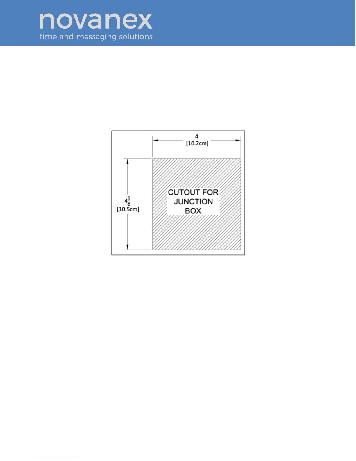
2. Cut a 4 1/8”x 4” (104.7mm x 101.6mm) hole in the drywall. (See Figure 3.)
Figure 3: Analog Clock Cutout Template
3. Mount the junction box (item 1 in Figure 4) to the stud or post in accordance with
local regulations.
OnTime Clock
Installation and User Guide
Firmware Version 1
All claims based on information publicly available at time of printing. All other product or service names mentioned
in this document may be trademarks of the companies with which they are associated.
© 2015 Novanex, Inc. | All rights reserved | page 9
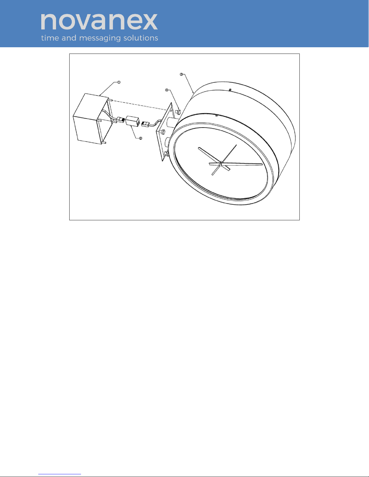
Figure 4: Analog Clock Double Mount Assembly
4. Route the data cable to the junction box in accordance with local regulations.
5. Plug the data cable into the connector (item 2 in Figure 4).
6. Mount the clock assembly (item 3 in Figure 4) to the studs on the junction box
and secure the unit with the nuts provided (item 4 in Figure 4).
7. For ceiling mount applications, the orientation of the clocks can be corrected by
removing the screws that secure the clocks to the housing and rotating the clock
90 degrees to the desired position.
4.6. Surface Mounting the Digital Clock
The following is a recommended procedure for surface mounting the digital clock. No
mounting kit is required.
1. Determine the clock mounting location.
2. Mark two points 10” (25.4 cm) apart which are level and centered on the data
cable outlet.
Note that both models are mounted with a ten inch distance between screw hole centers;
however, the best location for the wall jack varies. Refer to the templates in Figure 5
and Figure 6 to ensure that you line the wall jack up with the recess in the back of
the unit.

OnTime Clock
Installation and User Guide
Firmware Version 1
All claims based on information publicly available at time of printing. All other product or service names mentioned
in this document may be trademarks of the companies with which they are associated.
© 2015 Novanex, Inc. | All rights reserved | page 10
Figure 5: Mounting Template for 4-Digit Clocks
Figure 6: Mounting Template for 6-Digit Clocks
3. Insert two flat-head fasteners suitable for the wall surface at the marked points
and tighten.

OnTime Clock
Installation and User Guide
Firmware Version 1
All claims based on information publicly available at time of printing. All other product or service names mentioned
in this document may be trademarks of the companies with which they are associated.
© 2015 Novanex, Inc. | All rights reserved | page 11
4. Withdraw the fasteners until there is a 1/16” (.16cm) gap between the mounting
surface and the back of the fastener head.
5. Insert the data cable into the jack located at the back of the OnTime Clock.
6. Position the keyhole slots located on the rear of the clock over the fastener heads.
7. Pull the clock slightly downward until the unit is seated securely.
4.7. Pendant Mounting the Digital Clock –Single or Double
The following is a recommended procedure for pendant mounting. This procedure
requires a mounting kit (either ONT4KIT or ONT6KIT) and some additional hardware.
Figure 7: Digital Clock Pendant Mounting
1. Determine the clock mounting location.
Note: The illustration above suggests a recommended mounting means for a pendant
mount of one or more OnTime Clocks. Supplement the mounting kit with two
suitable locknuts and a length of ¾” (1.9 cm) pipe or conduit.
2. Mark the location where the clock assembly is to be mounted, making sure that
the mounting means is located beneath the data cable outlet.
3. Assemble and tighten the locknuts and pipe length as shown above.
4. Insert about 10 to 12 inches (30 cm) of data cable through the center hole of the
mounting kit. Securely attach the mounting means, using fasteners suitable for
the surface.
5. Lift an OnTime Clock into position and insert the data cable into the jack located
on the back of the clock.
6. Position the keyhole slots located on the rear of the clock over the mounting tabs.
7. Pull the clock slightly downwards until the unit is seated.
8. Repeat for the second clock if two clocks are being installed back-to-back.

OnTime Clock
Installation and User Guide
Firmware Version 1
All claims based on information publicly available at time of printing. All other product or service names mentioned
in this document may be trademarks of the companies with which they are associated.
© 2015 Novanex, Inc. | All rights reserved | page 12
4.8. Cantilever Mounting the Digital Clock –Single or Double
The following is a recommended procedure for cantilever mounting. This procedure
requires a mounting kit (either ONT4KIT or ONT6KIT).
Figure 8: Digital Clock Cantilever Mounting
1. Determine the clock mounting location.
2. Using the template provided, mark the location where the clock is to be
mounted, making sure the center is located over the data cable outlet.
3. Join the Ethernet Clock Mount and the Ethernet Clock Cantilever Wall Mount
using a #2 Phillips screwdriver and a 3/8” wrench. Make sure that the two
washers are fitted between the Clock Mount and the Cantilever Wall Mount.
Refer to Figure 9.
Figure 9: Digital Clock Mounting Kits
4. Insert 10 to 12 inches (30 cm) of data cable through the center hole of the
mounting unit.
5. Attach the unit to the wall with fasteners suitable for the surface.
6. Lift the clock into place and insert the data cable into the jack located on the back
of the clock.
7. Position the keyhole slots located on the rear of the clock over the mounting tabs
on the clock mount.
8. Pull the clock slightly downwards until the unit is seated securely.
9. Repeat for the second clock if clocks are being installed back-to-back.

OnTime Clock
Installation and User Guide
Firmware Version 1
All claims based on information publicly available at time of printing. All other product or service names mentioned
in this document may be trademarks of the companies with which they are associated.
© 2015 Novanex, Inc. | All rights reserved | page 13
4.9. Flush Mounting the Digital Clock
The flush mounting feature of the OnTime Clock provides an attractive, streamlined
mounting that blends with all room decors. This simple system hides the clock body,
while still giving full viewing access to the time face with no visible wiring.
The following is the recommended procedure for flush mounting.
1. Ensure that the location that is chosen for mounting is pre-wired with a data
network feed.
2. Cut an appropriately-sized opening into the wall. Refer to Table 2 for
appropriate dimensions for the opening.
Model
Vertical Dimension
Horizontal Dimension
4-Digit
12 3/8” or 31.4 cm
6 ½” or 16.5 cm
6-Digit
17 7/8” or 45.4 cm
Table 2: Dimensions for Mounting Digital Clock
Clearance within the wall should be at least 2 ½” (6.4 cm) deep to allow for the
clock body.
When cutting the opening please use the template provided. This will help ensure that
the opening is square as well as the proper size and in the correct location. For
the template, refer to Figure 10 and Figure 11.
Figure 10: Cut-out Template for 4-Digit Clocks

OnTime Clock
Installation and User Guide
Firmware Version 1
All claims based on information publicly available at time of printing. All other product or service names mentioned
in this document may be trademarks of the companies with which they are associated.
© 2015 Novanex, Inc. | All rights reserved | page 14
Figure 11: Template for 6-Digit Clocks
3. Using the template provided, locate the holes for the customer supplied
hardware.
4. Drill two 5/16” holes.
5. Once holes for the bolts have been made, install #6 molly anchors in the holes,
tighten until they expand, and then withdraw the screws.
6. Cut out the shaded area indicated on the template.
7. Install the data cable in the rear of the clock as shown in Figure 12. The clock is
now ready for installation.
Figure 12: Data Cable Installation

OnTime Clock
Installation and User Guide
Firmware Version 1
All claims based on information publicly available at time of printing. All other product or service names mentioned
in this document may be trademarks of the companies with which they are associated.
© 2015 Novanex, Inc. | All rights reserved | page 15
8. Place the clock/flush mount assembly in the hole and re-install the screws, as
seen in Figure 13.
Figure 13: Clock/Flush Mount Assembly
4.10.Power Up and Verification
Once the installation is complete, power up the units by connecting them to a PoE
enabled Ethernet LAN. Both the analog and digital clocks will follow the power up
sequence described below. Note that the process shown assumes the factory default of DHCP
addressing is in place.

OnTime Clock
Installation and User Guide
Firmware Version 1
All claims based on information publicly available at time of printing. All other product or service names mentioned
in this document may be trademarks of the companies with which they are associated.
© 2015 Novanex, Inc. | All rights reserved | page 16
Figure 14: Power Up Sequence
Table of contents


