NOVARDEN NSH35s User manual

EN
Mini pool heat pump
NSH35s/NSH55s
Installation and user manual

ENEN
User manual
Thank you for choosing NOVARDEN! We hope you are fully satised
using your appliance as part of your everyday routine.
If you should encounter situations that have not been properly
addressed in this User Manual or were to have any queries, do not
hesitate to contact us and a member of our technical customer service
department will be more than happy to answer your questions.
For more information, you can visit the ocial NOVARDEN website:
www.novarden.com
We reserve the right to make technical alterations to the appliance
without prior notice with the objective of continually improving our
products and customer satisfaction.
Please carefully read all instructions in this manual before using this
appliance. NOVARDEN will not be liable for damage due to incorrect
use.

1
Contents
EN
1
EN
Safety instructions and precautions ..........................2
Recommendations........................................................4
Appliance characteristics ............................................5
Box contents .........................................................................................5
Technical parameters...................................................6
Dimensions....................................................................7
Heat pump installation ................................................8
Installation diagram ..............................................................................8
Installation and required conditions ..................................................8
Location and dimensions .....................................................................9
Securing the frame ...............................................................................9
Ventilation .............................................................................................10
Auxiliary pump .....................................................................................10
Wiring ....................................................................................................10
Switching the pump on .......................................................................11
During operation..................................................................................11
Power cable connection ......................................................................12
Electrical wiring table...........................................................................13
Instructions ..................................................................14
Appliance test ..............................................................15
Maintenance.................................................................16
Troubleshooting...........................................................17
Table: Malfunctions and possible causes .........................................17
Fault codes ............................................................................................18
Warranty and after-sales service...............................19
Recycling instructions .................................................20

2
Safety instructions and precautions
EN
It is important to test the appliance’s installation circuit before and
after installing it to ensure that there are no gas leaks.
Gas must always be handled by a qualied gas professional. Never
attempt to repair the heat pump yourself.
• The appliance must be kept away from all ammable sources.
• In the event of a gas leak, switch o the appliance immediately
and contact your professional tter.
Soldering must only be carried
out by professionals in a repair
centre intended for such.
The appliance must be installed
outdoors in a ventilated area to
ensure good air circulation.
• The appliance must be installed by a professional. The user
must not make changes to the existing installation under any
circumstances.
• You must strictly follow the manufacturer’s guidelines when
servicing or filling gas. Please refer to the technical service
manual.
• Please avoid direct contact with the appliance’s air outlet and
protection grille.

3
Safety instructions and precautions
EN
• If you notice any abnormal conditions, such as a noise, smoke,
odour or an electrical leakage, immediately switch the appliance
off and contact your professional fitter.
• Do not use or store fuel or liquid gas such as thinners/solvents,
paint or petrol close to the appliance because it is a fire risk.
• To optimise the heating efficiency, insulate the hydraulic
connections between the swimming pool and the heat pump.
Use a suitable cover over your swimming pool.
• The hydraulic circuit between the swimming pool and the
appliance must be ≤10m otherwise heating efficiency may be
reduced.
• This appliance can reach a high efficiency level with an air
temperature between +10°C and +43°C.
• Avoid too high temperatures which would cause overheating or
too low, which would make water too cold.
• The appliance’s main power switch must be out of children’s
reach.
• If you experience a loss of power, the heat pump will automatically
reactivate once power is restored.
• Switch the appliance off during a power cut and reset the
temperature once the power is restored.
• In the event of a thunderstorm, switch off the main power switch
to avoid lightening damage.
• This appliance is not intended to be used by children or any person
with reduced physical, sensory or mental capacities, unless they
have been given supervision or instruction concerning use of the
device from a person responsible for their safety.
• If the appliance is not used for a long period of time, consider
unplugging it and draining it completely by opening the valve on
the inlet pipe.

4
Recommendations
EN
• Heat pump installation must be carried out by a qualified
professional.
• Adjust the temperature of the pool water to ensure that the
appliance operates effectively.
• Do not obstruct the air outlet to ensure optimal performance
and prevent it from becoming less effective.
• You can choose between different technical parameters
according to the user guide. However, this pool heat pump was
optimised at the factory.
• During transportation, it must be kept upright. Do not lift the
water connection. The titanium exchanger could become
damaged.
• Never plug in or use the appliance if it is damaged or defective.
• Please read carefully this manual before installing the appliance.
Strictly follow the instructions provided to ensure user safety
and avoid damaging the appliance.

5
Appliance characteristics
EN
5
• The appliance heats between 18°C and 40°C. The appliance’s
performance can vary depending on the weather conditions,
your geographical location, etc.
• For high performance, the ideal outdoor temperature is
between 10°C and 43°C.
• High performance titanium heat exchanger
• Precise temperature management with water temperature
display
• Eco-friendly R32 refrigerant
• GREE compressor (Landa)
• Easy to install and use
• The reference parameters may be subject to corrections
without prior notice as the product evolves and technical
improvements are made.
Box contents
3
4
1 2
1. Heat pump
2. Connectors (x2)
3. Clamps (x4)
4. User manual

Technical parameters
6
EN
Model NSH35s NSH55s
Operating temperature range
(°C) 10~43
Performance conditions: Air 27°C, Water 27°C, Humidity 80%
Max. swimming pool volume
(m3)20 32
Heating capacity (kW) 3.5 5.6
COP 5.0 5.9
Performance conditions: Air 15°C, Water 26°C, Humidity 70%
Max. swimming pool volume
(m3)12 20
Heating capacity (kW) 2.4 3.5
COP 3.8 4.1
Technical specifications
Rated input power (kW) 0.63 0.85
Rated input current (A) 2.7 3.7
Maximum input current (A) 4.0 6.5
Electrical power supply 230V 50Hz
Minimum water flow rate
(m3/h) 1~2 2~2.5
Hydraulic connection (mm) 32/38
Noise at 10m (dB) 26 27
Net weight (kg) 26 36
7
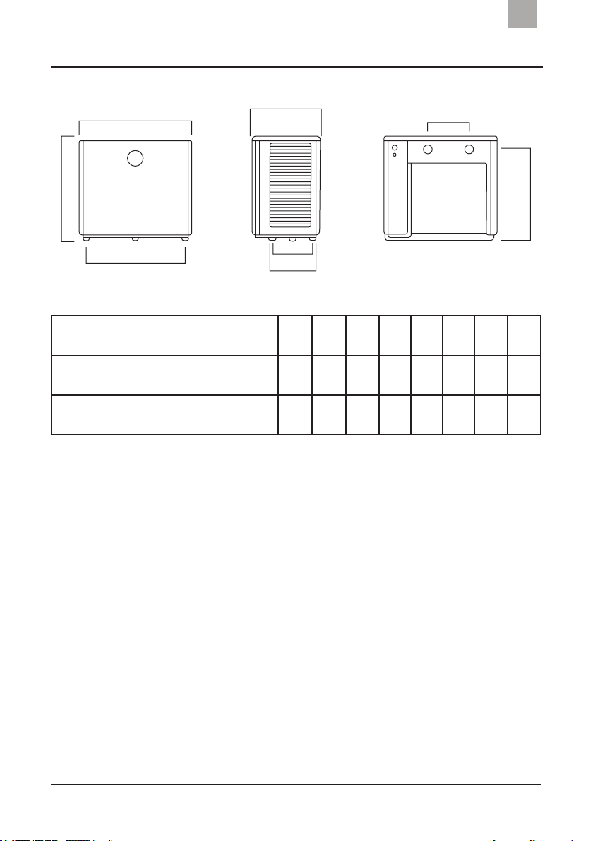
Dimensions
EN
Model/Dimensions (mm) /Letter A B C D E F G H
NSH35s 184 457 316 209 523 190 421 490
NSH55s 184 634 316 209 703 280 421 490
This data may be subject to change without notice.
NOTE: The heat pump diagram above is for the installation technician’s reference.
The product may change regularly without notice.
A
B
C
D
EF
G
H
8
Heat pump installation
EN
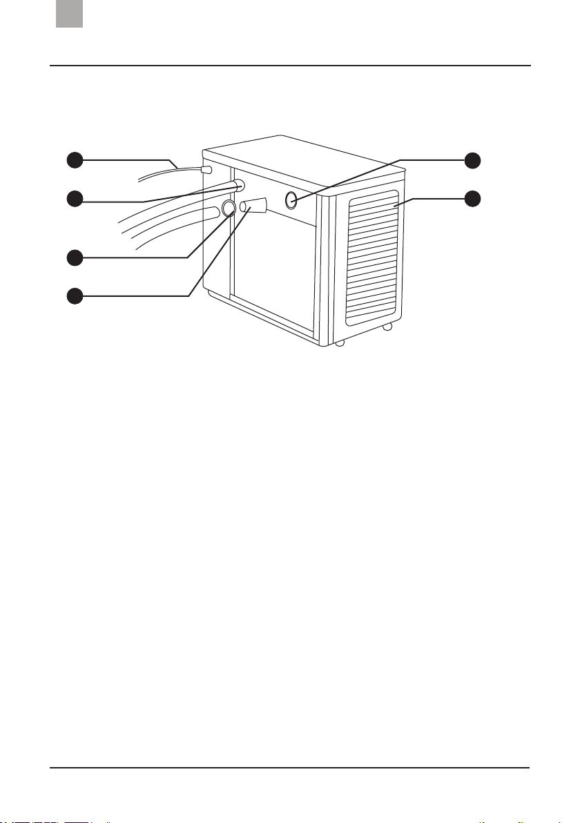
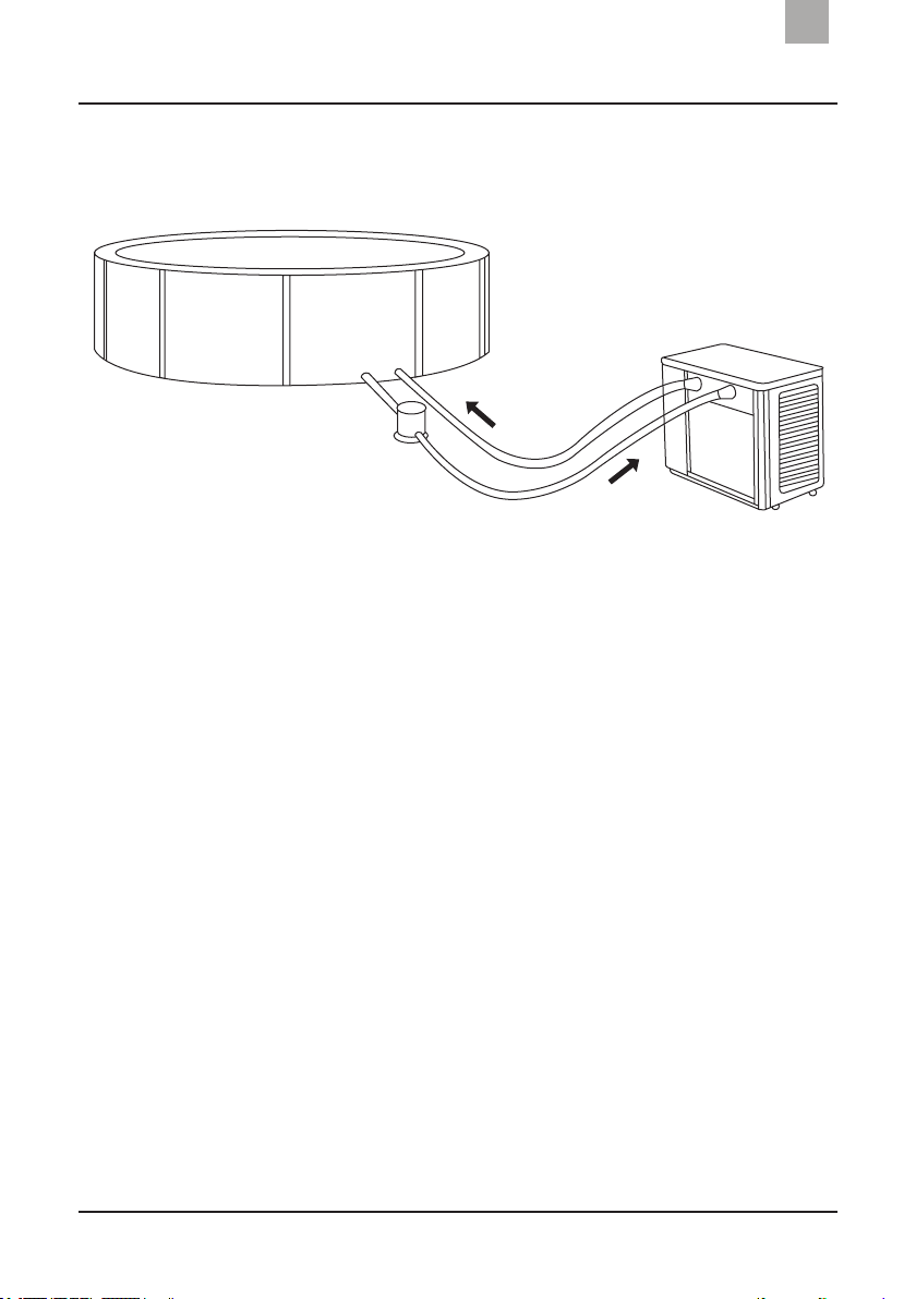
Installation diagram
Installation and required conditions
NOTE: This diagram including the hydraulic circuit is a reference material to facilitate
installation.
1. Power cable
2. Output
3. Pipe clamp
4. Connector
5. Input
6. Exterior protective grille
3
4
The heat pump must be installed by a qualied
professional. Unqualied users risk damaging the
appliance or compromising their own safety.
All chemical products must be added in the heat pump’s outlet pipe.
1
2
5
6
9
Heat pump installation
EN
Location and dimensions
Securing the frame
The heat pump must be installed in a well-ventilated area on a firm,
flat surface. The appliance must always be kept upright, in a vertical
position.
To ensure heating efficiency, the water pipe between the swimming
pool and the heat pump must be between 2m and 10m.
You must leave a space of at least 50cm between the heat pump and
any obstacle (wall, bush, etc.).
The appliance’s frame must be secured with nuts (M10) to a concrete
base or with brackets. The concrete base must be solid and stable
and the brackets must be protected against rusting.

10
Heat pump installation
EN
Ventilation
Auxiliary pump
Wiring
Do not obstruct ventilation. Incoming and outgoing air must be able
to circulate freely.
Keep a space of at least 50cm around the appliance otherwise the
machine’s efficiency could be reduced or even prevented.
The appliance needs to use an auxiliary pump (provided by the
manufacturer). To ensure the recommended pump flow rate, refer
to the technical parameters. Discharge head ≥10m.
Make sure the correct voltage is used to operate the appliance. Also
check that the appliance is correctly grounded. The wiring must be
undertaken by a professional technician and be in accordance with
the wiring diagram provided.
You must install a ground fault circuit interrupter in compliance
with the electrical installation legislation (leakage detecting current
≤ 30mA).
The power cable and interface cable must be installed in accordance
with current regulations and the cables must be connected
separately.

11
Heat pump installation
EN
During operation
It is normal to see condensate draining from the bottom of the
appliance. This is from the condensation from the water vapour in
the air when it goes into the exchanger. You must make sure water
can easily flow from of the pump.
Switching the pump on
After completing and checking the power cable installation, switch
the heat pump on. To use the appliance correctly, you must comply
with the following:
• Open the swimming pool pump, then open the heat pump
• Close the heat pump, then close the swimming pool pump.
12
Heat pump installation
EN
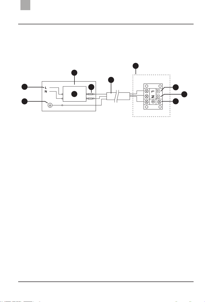
Power cable connection
For a power supply of 230V 50Hz
NOTE:
• The connection is wired. It must not have a connector.
• The heat pump must be grounded.
1. Power 230V 50Hz
2. Earth
3. Distribution box
(customer preparation)
4. Circuit breaker
5. Fuses
6. Power cable
7. Swimming pool heat pump
wiring closet
8. Phase cable
9. Neutral cable
10. Earth cable
3
4
5
6
7
8
9
10
1
2

13
Heat pump installation
EN
Electrical wiring table
Protection device options and cable specifications:
The data provided below may be subject to changes.
NOTE:
• The data below correspond to a power cable of ≤ 10 m. If the cable is > 10m, the
cable diameter must be increased.
• The cable must be in perfect condition. Electrical hazards may occur if the cable
is defective. In this case, contact the NOVARDEN Customer Services as soon as
possible.
• Never remove the power plug from the socket while the heat pump is in use.
This could cause serious electrical damage to your installation or personal
injury.
Model NSH35s NSH55s
Circuit
breaker
Current A 4.5 8
Differential mA 30
Fuse A 4.5 8
Power cable (mm²) 3x1.5
Signal cable (mm²) 3x0.5
R32 gas weight 250 460
14
Instructions
EN
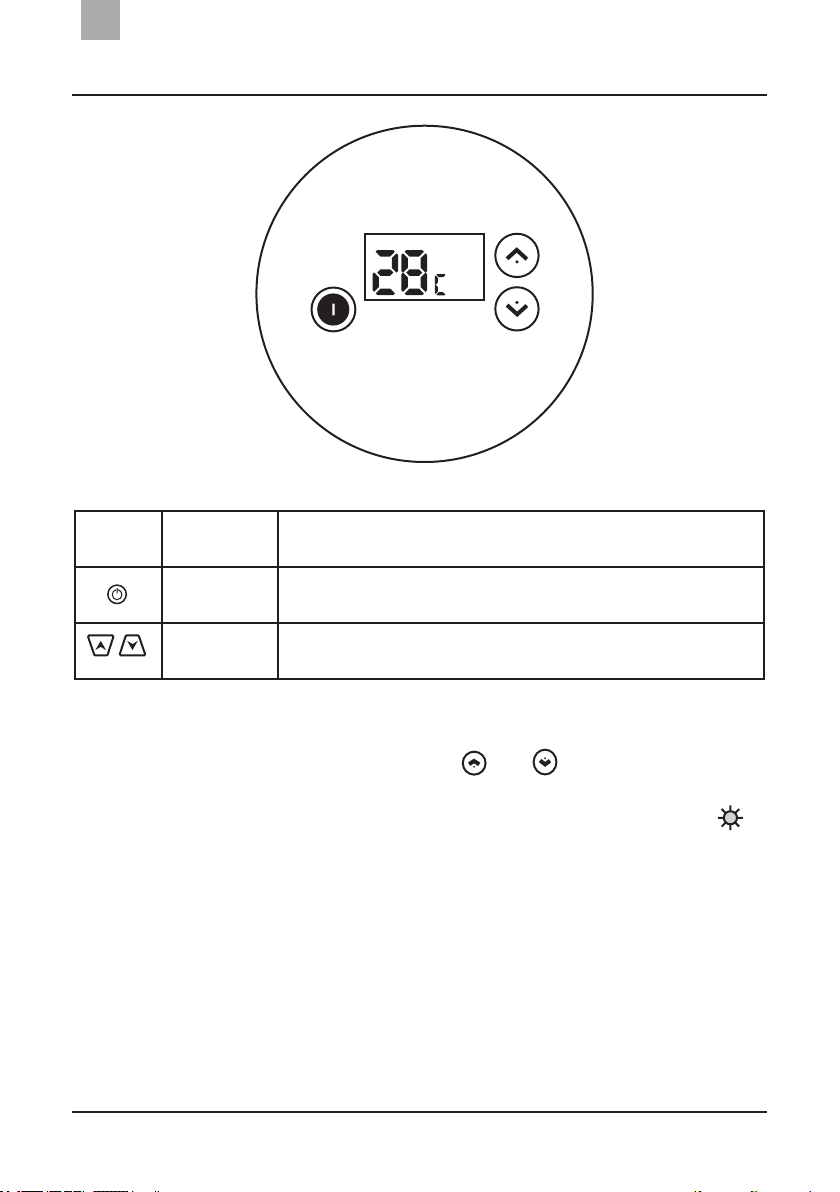
• Switch on heat pump by pressing the ON/OFF button.
• To adjust the temperature, press or . Use the arrows to
select the mode or to defrost the appliance.
• When the heat pump is in automatic defrosting mode “ ”
flashes on the display screen. Once finished, the pump will
automatically resume its heating programme.
NOTE: The interval between two forced defrost cycles must be more than 30
minutes.
Symbol Designation Operation
ON/OFF Press to switch the heat pump on or off
Up/down Press to adjust the water temperature or select the mode

15
Appliance test
ENEN
Check before use
Trial
You must check the appliance installation and hydraulic connections
referring to the installation diagrams. (See the “heat pump installation”
section on page 8). The wiring and grounding must also be checked.
(See the “power cable connection” section on page 12).
Ensure that the appliance’s main switch is on OFF and check the
temperature setting.
Check the ventilation device and outlets operate correctly and are
not obstructed.
Complete a airtightness check in a ventilated space. This control
must not be carried out in a closed space.
If you suspect a leak, stop using the heat pump and contact
NOVARDEN’s Customer Services.
It is normal to see condensate draining from the bottom of the
appliance. This is from the condensation from the water vapour in
the air when it goes into the exchanger. You must make sure water
can easily flow from of the pump.

16
Maintenance
EN
Risk of electric shock: switch the appliance off before carrying
out any maintenance on it.
During the winter season, when you do not use the swimming pool:
• Switch the appliance off to avoid damaging the machine.
• Drain all water from the machine.
• Cover the appliance with a tarpaulin to protect it from dust.
Important:
Unscrew the inlet pipe connection to let the water out.
If water remains in the appliance and freezes and the titanium
exchanger could be damaged.
Only clean the machine with household cleaning products or
clean water. Never use petrol-based products, thinners or similar
combustible products.
Regularly check the nuts, cables and connections.
Contact the Customer Services department if the appliance requires
an intervention or repairs. Never attempt to repair the appliance
yourself to avoid risk of personal injury.
The NOVARDEN warranty shall be null and void if you were to carry
out an intervention yourself.
17
Troubleshooting
ENEN
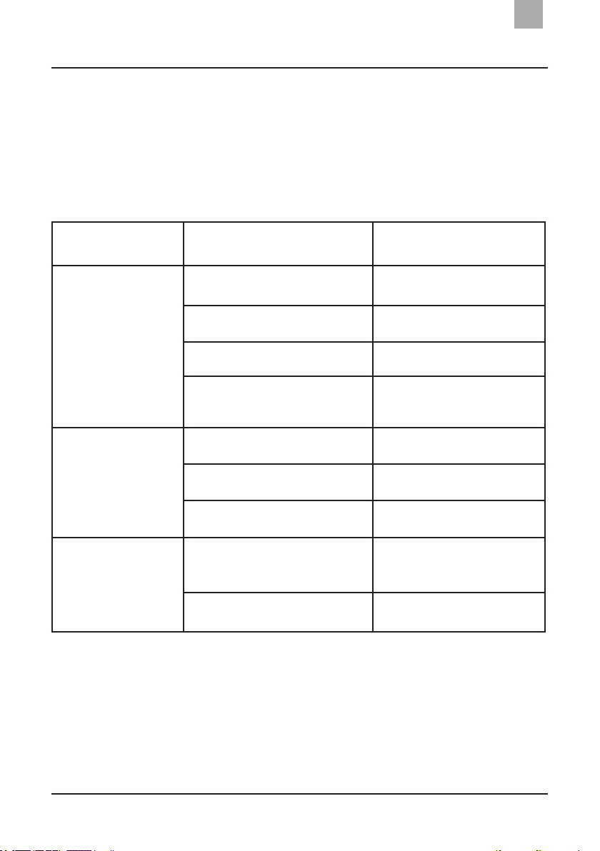
Table: Malfunctions and possible causes
Faults Reason Solution
The heat pump does
not work
No power Wait until the power is
restored
Appliance is off Switch it on
Fuse blown Check and change the fuse
Circuit breaker off Check and install the circuit
breaker
The fan turns but with
insufficient heating
Evaporator blocked Remove obstacles
Air outlet blocked Remove obstacles
3 minutes to start up Wait patiently
Normal display but no
heating
Temperature setpoint too low Adjust the heating
temperature
3 minutes to start up Wait patiently
If none of the above-mentioned steps provide a solution for your
problem, please contact your fitter or the NOVARDEN after-sales
department. Never attempt to repair the appliance yourself.
Only qualified technicians holding a valid refrigerant product repair
certificate should repair the NOVARDEN NSH35s or NSH55s heat
pumps.
18
Troubleshooting
ENEN
NOTE: If you notice any of the following situations, stop the appliance and
immediately switch it off using the main switch. Contact your professional fitter in
case of an unexpected power cut or if the fuse or circuit breaker trip regularly.
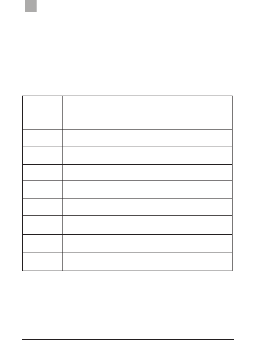
Fault codes
Error code Failure description
PP1 Inlet water temperature sensor failure
PP2 AIN2 connected temperature sensor failure
PP3 AIN3 connected temperature sensor failure
PP4 Gas return temperature sensor failure
PP5 Exterior temperature sensor failure
PP7 Exterior temperature too low
EE1 System pressure too high
EE2 System pressure too low
EE3 Water flow switch failure
This manual suits for next models
1
Table of contents
Languages:
Popular Swimming Pool Pump manuals by other brands

Calpeda
Calpeda MPC operating instructions

Pentair Pool Products
Pentair Pool Products Pump Waterfall Operation and service manual

Intex
Intex 128366NP owner's manual

Kripsol
Kripsol KS Evo VS 150 user guide

Pentair Pool Products
Pentair Pool Products Challenger brochure

Zodiac
Zodiac FloPro VS Instructions for installation and use


Clarke
Clarke SPP15A Operation & maintenance instructions

Theralux
Theralux Theratherm User and service manual

Kripsol
Kripsol Ondina OK Series Handbook for use and maintenance

Intex
Intex 128638GS owner's manual

Pentair Pool Products
Pentair Pool Products MAX-E-PRO owner's manual

Hayward
Hayward Power-Flo Matrix Series Installation and operating instructions