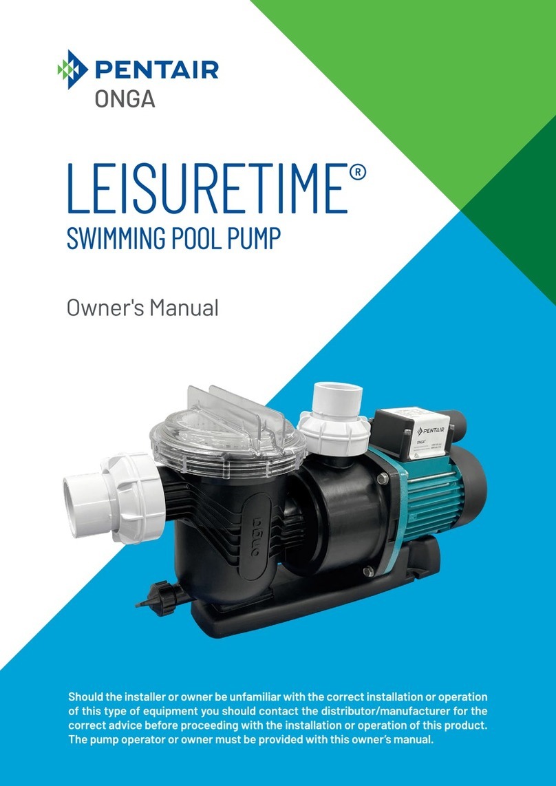
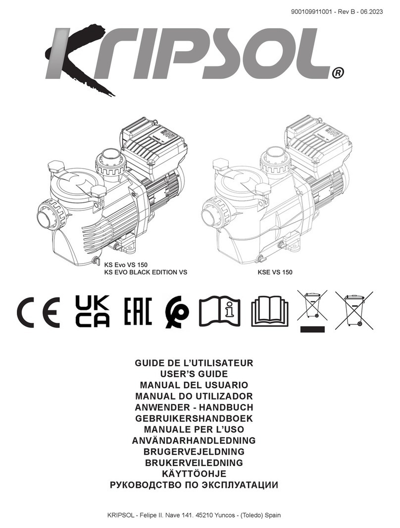
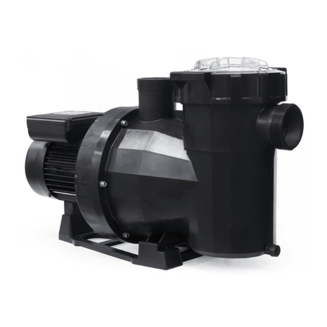
Kripsol KS Evo VS 150 User manual

GUIDE DE L’UTILISATEUR
USER’S GUIDE
MANUAL DEL USUARIO
MANUAL DO UTILIZADOR
ANWENDER - HANDBUCH
GEBRUIKERSHANDBOEK
MANUALE PER L’USO
ANVÄNDARHANDLEDNING
BRUGERVEJELDNING
BRUKERVEILEDNING
KÄYTTÖOHJE
РУКОВОДСТВО ПО ЭКСПЛУАТАЦИИ
KRIPSOL - Felipe II. Nave 136. 45210 Yuncos - (Toledo) Spain
IS27000VSTD - Rev D
KS Evo VS 150
273,3
206,5
16
311,8
244
152
302
604.5
G. 2 3/4"
G. 2 3/4"
265,5
104,5
23
210
TOLERANCIAS GENERALES DE GRADOS S/DIN 7168 G/M
ESCALA
> 30 < 120
ED.
BOMBA KSX PRO VS
FIRMA
SUSTITUYE A:
DIBUJADO
< 6
15/11/17
USADO EN:
± 0,2
ZULIMA
MATERIAL:
± 0,5
NOMBRE
> 120
1/1
TOLERANCIAS GENERALES
FECHA DESCRIPCION
Nº DE PLANO:
SUSTITUIDO POR:
COMPROB.
± 0,1
DENOMINACION:
± 0,3
15/11/17
FECHA
> 6 < 30
la cual es la propietaria del dibujo.
total o parcial ni su comunicación ni entrega a terceros. Ha
Este dibujo contiene información confidencial y es propiedad
de devolverse tan pronto como sea requerido por KRIPSOL,
de KRIPSOL, sin autorización expresa no se permite su copia
244
16
206,5
311,8
189
104,5
265,5
G. 2 3/4"
152
302
604,5
23
G. 2 3/4"
210
TOLERANCIAS GENERALES DE GRADOS S/DIN 7168 G/M
ESCALA
> 30 < 120
ED.
BOMBA KS EVO VS
FIRMA
SUSTITUYE A:
DIBUJADO
< 6
15/11/17
USADO EN:
± 0,2
ZULIMA
MATERIAL:
± 0,5
NOMBRE
> 120
1/1
TOLERANCIAS GENERALES
FECHA DESCRIPCION
Nº DE PLANO:
SUSTITUIDO POR:
COMPROB.
± 0,1
DENOMINACION:
± 0,3
15/11/17
FECHA
> 6 < 30
la cual es la propietaria del dibujo.
total o parcial ni su comunicación ni entrega a terceros. Ha
Este dibujo contiene información confidencial y es propiedad
de devolverse tan pronto como sea requerido por KRIPSOL,
de KRIPSOL, sin autorización expresa no se permite su copia
KSEVS 150

KRIPSOL - Felipe II. Nave 136. 45210 Yuncos - (Toledo) Spain
KEEP THIS MANUAL FOR FUTURE REFERENCE
VARIABLE SPEED
CENTRIFUGAL PUMP
USER GUIDE
IS27000VSTD - Rev D
273,3
206,5
16
311,8
244
152
302
604.5
G. 2 3/4"
G. 2 3/4"
265,5
104,5
23
210
TOLERANCIAS GENERALES DE GRADOS S/DIN 7168 G/M
ESCALA
> 30 < 120
ED.
BOMBA KSX PRO VS
FIRMA
SUSTITUYE A:
DIBUJADO
< 6
15/11/17
USADO EN:
± 0,2
ZULIMA
MATERIAL:
± 0,5
NOMBRE
> 120
1/1
TOLERANCIAS GENERALES
FECHA DESCRIPCION
Nº DE PLANO:
SUSTITUIDO POR:
COMPROB.
± 0,1
DENOMINACION:
± 0,3
15/11/17
FECHA
> 6 < 30
la cual es la propietaria del dibujo.
total o parcial ni su comunicación ni entrega a terceros. Ha
Este dibujo contiene información confidencial y es propiedad
de devolverse tan pronto como sea requerido por KRIPSOL,
de KRIPSOL, sin autorización expresa no se permite su copia
244
16
206,5
311,8
189
104,5
265,5
G. 2 3/4"
152
302
604,5
23
G. 2 3/4"
210
TOLERANCIAS GENERALES DE GRADOS S/DIN 7168 G/M
ESCALA
> 30 < 120
ED.
BOMBA KS EVO VS
FIRMA
SUSTITUYE A:
DIBUJADO
< 6
15/11/17
USADO EN:
± 0,2
ZULIMA
MATERIAL:
± 0,5
NOMBRE
> 120
1/1
TOLERANCIAS GENERALES
FECHA DESCRIPCION
Nº DE PLANO:
SUSTITUIDO POR:
COMPROB.
± 0,1
DENOMINACION:
± 0,3
15/11/17
FECHA
> 6 < 30
la cual es la propietaria del dibujo.
total o parcial ni su comunicación ni entrega a terceros. Ha
Este dibujo contiene información confidencial y es propiedad
de devolverse tan pronto como sea requerido por KRIPSOL,
de KRIPSOL, sin autorización expresa no se permite su copia
KS Evo VS 150 KSEVS 150

USE ONLY KRIPSOL GENUINE REPLACEMENT PARTS
Page 2 of 14 Pump
WARNING – Disconnect the pump from the main power supply completely before servicing the pump or filter.
WARNING – All electrical connections must be done by a qualified electrician according to local electrical standard.
FNF C 15-100 GB BS7671:1992
DDIN VDE 0100-702 EW EVHS-HD 384-7-702
AÖVE 8001-4-702 HMSZ 2364-702:1994 / MSZ 10-533 1/1990
EUNE 20460-7-702 1993, REBT ITC-BT-31 2002 MMSA HD 384-7-702.S2
IRL IS HD 384-7-702 PL PN-IEC 60364-7-702:1999
ICEI 64-8/7 CZ CSN 33 2000 7-702
LUX 384-7.702 S2 SK STN 33 2000-7-702
NL NEN 1010-7-702 SLO SIST HD 384-7-702.S2
P RSIUEE TR TS IEC 60364-7-702
WARNING – Be certain the machine is only plugged into a protected 230 V outlet that is protected from short-circuits.
The pump is to be supplied by an isolating transformer or supplied through a residual current device (RCD) having a rated
residual operating current not exceeding 30 mA.
WARNING – Children should be supervised to ensure that they do not play with the appliance. Keep ngers and foreign
objects away from openings and moving parts.
WARNING – Motor must be suitably grounded. Connect ground wire to green grounding screw and for cord connected
units use properly grounded outlet.
WARNING – Use a motor bonding lug to connect motor with other bonded parts using the appropriate size conductor
as required by electrical codes.
WARNING – When making these electrical connections, refer to the diagram given under the lid of the motor terminal
box. Be sure to check the electric connections are tight and sealed before powering up. Replace all covers before operation.
WARNING – Make sure that the power supply voltage required by the motor corresponds to that of the distribution
network and that the power supply cables matches the power and current of the pump.
WARNING – Read and follow all instructions in this owner’s manual and on the equipment. Failure to follow
instructions can cause serious injury or death.
This document should be given to the owner of the swimming pool and must be kept by the owner in a safe place.
WARNING – The appliance can be used by children aged from 8 years and above and persons with reduced physical,
sensory or mental capabilities, or lack of experience and knowledge, if they have been given supervision or instruction
concerning use of the appliance in a safe way and understand the hazards involved.
WARNING – Cleaning and user maintenance shall not be made by children without supervision.
WARNING – The pump is intended for continuous operation at Maximum Water temperature 35°C.
WARNING – Use Only Genuine Kripsol Replacement Parts.
WARNING – If the supply cord is damaged it must be replaced by the manufacturer, service agent, or similarly qualified
persons in order to avoid a hazard.
WARNING – For disconnection from main power supply an external switch having a contact separation in all poles that
provide a full disconnection under overvoltage category III conditions must be incorporated in the fixed wiring in accordance
with the wiring rules.
WARNING – Do not operate the swimming pool pump if the power cord or the housing of the motor connection box is
damaged. This can cause an electric shock. A damaged power cord or motor connection box must be replaced by a service
agent or a similarly qualified person immediately in order to avoid a hazard.
WARNING – This pool motor is NOT equipped with a Safety Vacuum Release System (SVRS). SVRS helps prevent
drowning due to body entrapment on underwater drains. In some pool configuration, if a person’s body covers the drain, the
person can be trapped by suction. Depending on your pool configuration, a SVRS may be required to meet local requirements.
WARNING: Electrical Hazard. Failure to follow
instructions can result in serious injury or death.
FOR USE WITH SWIMMING POOLS
USE ONLY KRIPSOL GENUINE REPLACEMENT PARTS
Page 3 of 14 Pump
GENERAL POINTS
Congratulations, you have just acquired a Kripsol variable speed pump®.
Kripsol variable speed pumps®have a state-of-the-art permanent-magnet motor with AC electronic switching. This motor
is controlled by a microprocessor combined with a frequency variator providing the following characteristics:
•Rotation speed is displayed on the control display
•3 factory preset rotation speeds (buttons V1, V2, V3), as well as custom speeds set by the user
•Regular priming each time you switch on, with adjustable speed and duration
•Skimmer function, which skims the water's surface
•Programmable Timer function
•Current power usage displayed
•Partial and total power consumption displayed
•Running time of the pump displayed
•Low noise level
•Construction standard TEFC IP55
Install the pump at a suitable distance from the pool to reduce the distance between the suction point and the pump as
much as possible to avoid pointless excessive pressure drops on the hydraulic circuit.
However, it is essential to comply with the safety distance required by the current installation standard (3.5 m minimum).
Install and use the product at an altitude less than 2000 m
ZONE 2 ZONE 2
ZONE 0
1,50 m
2,50 m
2,50 m
1,50 m 2,00 m 2,00 m 1,50 m
ZONE 1
1,50 m
OK OK
3.5 m
ZONE 0
Install the pump in a dry, well-ventilated place. The motor requires the air to circulate freely around it to allow natural
ventilation. Clear a space of at least 0.5m around the pump. Check regularly that no objects, leaves or other debris are
blocking the motor cooling system.
The pump must be installed to ensure that the external disconnection switch incorporated into the fixed unit is visible and
easily accessible. The switch must be located near to the pump.
The pump must be permanently installed on a concrete base using 8mm lag screws suitable for concrete, screwed into
drilled implantation holes. Lock washers must be used to prevent the installation lag screws working loose over time. If
the pump has to be mounted on a wooden board, Ø 8 mm hexagonal wood screws must be used combined with lock
washers to prevent the screws working loose over time.
Install the pump under shelter to avoid the control unit being subject to heavy splashing.
The acoustic pressure of Kripsol pumps is less than 67 dB (A).
Necessary measures:
•Connect the pump to the earth: Never operate the pump unless it is connected to the earth.
•Connect the pump with a H07RN-F 3G1mm² type cable (D max 7,8mm)
•Include a 30 mA differential protection to protect people against electric shocks which may be caused by a breach of
the equipment's electrical insulation.
•Include short-circuit protection (the rating is determined according to the value given on the nameplate on the motor).
•Include a means of disconnection from the power supply having an opening distance on the contacts of all the poles
ensuring the power supply is completely cut off under the conditions of a category III overvoltage.
WARNING: Wait 5 minutes after having totally disconnected the pump from the power supply before carrying out any
operation on the motor or the connection box: Danger of electric shock which may cause death.
The electric motors fitted to our pumps have thermal protection. This protection reacts in the event of overload or
abnormal temperature rise in the motor winding. This protection automatically resets when the winding temperature drops.
Whatever the type of motor used, if the regulations require it, a magnetic thermal protection must be installed in addition
to the measures described above, which must be calibrated according to the information on the motor's nameplate.
The table on page 170 gives the various characteristics of the motors fitted to our pumps.

USE ONLY KRIPSOL GENUINE REPLACEMENT PARTS
Page 4 of 14 Pump
Electrical connection: Ensure that the supply voltage required by the motor corresponds to that of the distribution network
and that the section and length of the power cable are adapted to the power and current of the pump.
All the electrical connections on the pump and any change of power cable must be done by a qualified professional to avoid
any danger.
When carrying out the electrical connections, comply with the identification under the connection terminals.
Check that the electrical connections are correctly tightened and watertight before switching on the power.
Ensure the cable runs correctly through the opening and ferrite provided for this purpose. The cable gland ensures
watertightness around the cable, and the ferrite acts as a filter against electromagnetic disturbance.
Any pre-wiring on our pumps must be removed when the pump is permanently connected to the power supply. This
preparation is only used for testing at the factory during the manufacturing phases.
INSTALLATION
Install the pool pump so as to reduce pressure drops to a minimum whilst complying with the distances specified in the
installation standard, namely 3.5m minimum between the pump and the pool. The suction pipe must be installed with a slight
uphill incline towards the pump axis. Ensure that the connections are correctly tightened and watertight. However, avoid
excessively tightening the pipes. For plastic materials, use Teflon only to ensure watertightness. The diameter of the suction
pipe shall depend on that of the discharge pipe. Avoid damp or non-ventilated locations. The motor requires the cooling air
to circulate freely. Install the pump under shelter to avoid the control unit being subject to heavy splashing.
INSTRUCTIONS FOR START-UP AND PRIMING: Fill the body of the strainer with water up to the level of the suction pipe.
Never run the pump without water, as the water is necessary for cooling and lubrication of the mechanical shutter. Open
all the suction and discharge pipe valves, and the filter air purge valve if there is one. (Any air in the suction pipes must be
eliminated). Start up the generator and wait a reasonable time for priming. Five minutes is not excessive for priming (this
time depends on the suction head and the length of the suction pipe). If the pump does not start or does not prime, please
refer to the troubleshooting guide.
USING THE CONTROL PANEL
1. INTRODUCTION
Kripsol®'s variable speed pump is operated through a control panel that visually displays the operating settings and allows
you to adjust them as well as program the Timer mode.
1Power on LED
2LCD display screen
3Choosing the speed
4Switching between Manual/Timer modes
5Up/down buttons
6Start/Stop button
7Display settings button
8Selected speed LEDs
1
2
3
4
5
6
7
8
The pump is delivered with DEFAULT SETTINGS(factory settings):
Priming time
(seconds) Priming
speed (rpm) V1
(rpm) V2
(rpm) V3
(rpm)
Skimmer
time
(minutes)
Skimmer
cycle (hours) Skimmer
speed (rpm)
240 3000 1500 2400 3000 15 1hr 2800
rpm: Rotations per minute

USE ONLY KRIPSOL GENUINE REPLACEMENT PARTS
Page 5 of 14 Pump
2. PUMP OPERATING MODES
2.1 Manual mode
In manual mode, the user can switch the pump on or off manually,
according to when the pool is being used.
•When you switch the pump on, it launches a priming phase (a).
You can adjust this phase (speed and duration, section 4.2). Priming
may be interrupted during start up (section 3.2) or deactivated in the
settings.
•The pump speed then stabilizes to a constant rate
(b) (stabilization to V2 by default). The user can choose and adjust
the speed (section 3.3).
•After switching off and then restarting, the pump will stabilize at the
last recorded rate.
(a)
(b)
speed
time
2.2 Skimmer
The Skimmer function allows the pump to skim just the water's
surface, which is especially useful for preventing dirt from
accumulating and stagnating at the surface of the pool.
•The function is automatic: the pump will run at a higher speed
(c) for a while and according to a set cycle - both of which you can
adjust.
•After running at a higher speed, the pump will adjust to its normal
rate - this is the case in both the Manual and Timer modes.
•You can deactivate the Skimmer function (see settings in
section 4.3).
(c)
speed
time
2.3 Timer mode
When using the Timer mode, the pump is run automatically 24/7. The
user can program (d) the different speed presets. They are selected
depending on the installation (heating mode, energy-saving mode
etc.) and according to the times the pool is used.
•If the Skimmer function is activated, its sequence will superimpose
on the timer one.
•You can stop the pump (pause it) in the Timer mode. When you
start it up again, it will run at the speed of the current 'Timer' mode.
•For information on how to program the Timer mode, see section 4.5.
(d)
speed
time
2.4 Switching between Manual and Timer modes
You can switch between modes by pressing the button as shown below:
Manual mode Timer mode
Displayed speed without
prefix 2400 Displayed speed with
prefix 't' t2400
The illuminated LED
indicates the selected
speed (V2 by default)
The LEDs are switched
off

USE ONLY KRIPSOL GENUINE REPLACEMENT PARTS
Page 6 of 14 Pump
2.5 Connecting external digital inputs
CAUTION: Before carrying out any electrical work on the pump, unplug the power cord and wait 5 min.
The filtration pump is equipped with a 3-m long 5-wire cord for connecting the 4 digital inputs or potential-free dry contacts
(Open/Closed).
Examples of digital inputs
•Assign the speed and flow required for the peripheral devices, such as a heat pump, roller blind or robotic vacuum, etc.
to work properly.
•Install a user interface control unit. These digital inputs are used to control, from a distance of 3 m, the Run/Stop
function as well as the 3 speeds (V1-V2-V3).
Assigning the wires DI1
DI2
DI3
DI4
C
3 m
DI1 Brown Speed V1
DI2 Green Speed V2
DI3 White Speed V3
DI4 Red Run/Stop
CBlack Common
N.B.
•If the digital inputs are partially used, electrically insulate the unused wires.
•If the digital inputs are unused, insert the connector (A) instead of the 5-wire cord (see figure below).
A

USE ONLY KRIPSOL GENUINE REPLACEMENT PARTS
Page 7 of 14 Pump
Operation with the digital inputs
The digital inputs can be operated in Manual or Timer
mode.
They have the highest priority level: they act as
MASTER over all the functions currently in use.
Only the Run/Stop and DISP/FUNC buttons remain
active.
When a digital input is used, the LED associated with
the speed in question blinks rapidly
(DI1 = V1, DI2 = V2 or DI3 = V3).
To obtain an action through the digital inputs, the DI4
input must be closed. DI4 Run/StopClosed
If several digital inputs are switched simultaneously,
only one will be carried out in the order of priority
specified in the table opposite.
DI1 = V1 DI2 = V2 DI3 = V3
DI1 = V1 V1 V2 V3
DI2 = V2 V2 V2 V3
DI3 = V3 V3 V2 V3
N.B. Once the action associated with the digital input is complete (open contact),
the filtration pump resumes the action for the current operational mode.
If the DI4 digital inlet is open, the filtration pump will
not start and dSTOP will be displayed on the pump's
screen.
•Close the DI4 inlet.
•If necessary press RUN/STOP to start the filtration
pump.
DI1
DI2
DI3
DI4
C
dStoP
A
or

USE ONLY KRIPSOL GENUINE REPLACEMENT PARTS
Page 8 of 14 Pump
3. OPERATING THE PUMP
3.1 Power on
'Power' lights up and an LCD test runs on screen,
then the software version is displayed on screen r1626
88888
. . . . . . . .
3.2 Priming phase
After switching on the pump, the priming phase starts automatically (this is the same after restarting the pump).
Priming phase begins automatically:
•The speed will climb to 3000 rpm and will last 240
seconds (default settings)
Pr 3000
End of priming phase:
•The pump will stabilize at V2 by default or at the
last recorded speed.
•The corresponding LED lights up (Manual mode)
2400
To display the remaining time of the priming phase:
•Press DISP/FUNC
•The remaining time is displayed in seconds
219
To stop the priming phase before it finishes:
•Press RUN/STOP
•The speed will stabilize by default at V2 or at the
last recorded speed
2400
3.3 In Manual mode: selecting, setting and saving a custom speed
To select a speed:
•Press one of the speed preset buttons
•The default value will be displayed (in rpm)
•The corresponding LED will light up
1500
To set a new speed:
•Press the up / down buttons
•The LED will blink: setting speed
•Choose the speed you want (between 600 and
3000 rpm)
1640
To save the new speed:
•Press and hold the speed preset button for 3 s
•The LED will show a constant light once the speed
has been saved
>3s 1640
Note: The water flow generated by the pump speed must be adapted to the volume capacity of the installed parts (filter,
pipes...). If you are unsure call a professional.
3.4 Stopping / restarting the pump
To stop the pump:
•Press RUN/STOP
•The pump will stop and the speed preset LED will
remain illuminated
•In Manual mode the screen will display 'StoP'
In Timer mode the screen will flash 'StoP'
StoP
StoP
To restart the pump:
•Press RUN/STOP
•The pump will begin its priming phase (section 3.2)
•Speed stabilization:
in Manual mode this will be the last recorded speed
in Timer mode this will be the operating speed of
the Timer preset
1640
t2400

USE ONLY KRIPSOL GENUINE REPLACEMENT PARTS
Page 9 of 14 Pump
4. SETTINGS
Note: To adjust the settings the pump must be powered on and in Manual mode (section 2.4), switched off or running
(post priming phase).
If no button is pressed for 2 minutes, the display will go back to normal (showing the speed or StoP) and the
settings will not be saved.
4.1 Setting the clock
•Press and hold DISP/FUNC for 3 seconds
All three LEDs will blink
•The screen will display "ConF" and then "hr" >3s
ConF
h r
•Press DISP/FUNC to show the time on the internal
clock (hh-min) 07-38
•Press the up / down buttons to adjust the hours /
minutes 15-38 15-10
•Press RUN/STOP to exit and save
The display will show the current speed or StoP StoP
/
1640
Note: Adjusting the time on the internal clock is important in Timer mode.
It will remain saved if the pump is switched off.
4.2 Setting the priming phase
•Press and hold DISP/FUNC for 3 seconds
All 3 LEDs will blink and the screen will display
"ConF" >3s
ConF
•Press DISP/FUNC repeatedly until 'Pr 240' is
displayed on screen - the default priming time
(seconds) x n Pr240
•Press the up / down buttons to set the desired
value (0 to 300 seconds) Pr 80
•Press DISP/FUNC: the screen will display "o3000"
as default priming speed (rpm) o3000
•Press the up / down buttons to display the desired
value (max. 3000 rpm) o2660
•Press RUN/STOP to exit and save
The display will show the current speed or StoP StoP
/
1640
Note: If the priming time is set to zero the screen
will display "ProFF": priming has been
deactivated
ProFFPr 0

USE ONLY KRIPSOL GENUINE REPLACEMENT PARTS
Page 10 of 14 Pump
4.3 Setting the Skimmer function
See section 2.2 for an introduction to this function
•Press and hold DISP/FUNC for three seconds
All three LEDs will blink and the screen will display
"ConF" >3s
ConF
•Press DISP/FUNC repeatedly until 'SFO.15' is
displayed on screen: this is the default Skimmer
time (in minutes) x n SfO15
.
•Press the up / down buttons to set the desired
value (0 to 30 minutes) SFO20
.
•Press DISP/FUNC: the screen will display "St 1hr"
- this is the default Skimmer cycle period St1h
•Press the up / down buttons to set the Skimmer
cycle period to 1hr, 2hrs or 3hrs St2h
•Press DISP/FUNC: the screen will display "S2800"
- this is the default speed of the Skimmer function
(rpm)
S2800
•Press the up/down buttons to display the desired
speed (600 to 3000 rpm) S2680
•Press RUN/STOP to exit and save
The display will show the current speed or StoP StoP
/
1640
Note: To deactivate the Skimmer and set the time to
zero - display reads "SFoFF" SFoFFSF000
4.4 Restoring the settings
To restore the default settings and erase the Timer mode settings, do the following:
•Press and hold DISP/FUNC for three seconds
All three LEDs will blink and the screen will display
"ConF" >3s
ConF
•Press DISP/FUNC repeatedly until the screen
displays the message 'Init' x n Init
•Press and hold the 'up' button for 3 seconds. The
screen will read "donE" once the reset is complete StoP
dOnE
>3s
Reminder: default settings and their value ranges
Priming Speed preset buttons Skimmer function Timer function
Pr o___ V1 V2 V3 SF St S___ t0 t1 _ t5
Units s rpm rpm rpm rpm min h rpm hh-min rpm hh-min rpm
Default 240 3000 1500 2400 3000 15 1 2800 06-00 2400 oFF 0
Mini 0 (oFF)600 600 600 600 0 (oFF)1 ... 600 00-00 — 00-00 0/ 600
Maxi 300 3000 3000 3000 3000 30 ... 3 3000 24-00 — 24-00 3000

USE ONLY KRIPSOL GENUINE REPLACEMENT PARTS
Page 11 of 14 Pump
4.5 Setting the Timer mode
The control panel allows you to program multiple sequences
(see section 2.3) or Timers t0 to t5, which do not need to follow a
chronological order.
Unused Timer settings will be deactivated.
Timer 't0' can be set to 00:00, 06:00 (by default), 12:00 or 18:00. It
cannot be deactivated.
You cannot adjust the speed of t0, it is set at 2400 rpm
speed
time
t0
t1
t3
(t2)
t4
t5
•Identify the speed profile you would like to program.
The image opposite is shown as an example.
•Check whether the internal clock has been set correctly.
•Press and hold DISP/FUNC for 3 seconds
All 3 LEDs will blink and the screen will display
"ConF" >3s
ConF
•Press DISP/FUNC twice and the screen will
display "t0" x 2
t 0
•Press DISP/FUNC: the screen will display "06-00" -
this is the default value of t0 06-00
•Press the up / down buttons to set the value you
would like for t0 (00-00, 06-00, 12-00 or 18-00) 18-00
•Press DISP/FUNC: the screen will display "t1oFF" t1off
•To activate this Timer setting (as an example),
press the 'up' button. The screen will display "t1
on"
t1 on
•Press DISP/FUNC: the screen will display "00-00" 00-00
•Press the up / down buttons to set the desired
timetable (hh-mm) 20-00 20-15
•Press DISP/FUNC: the screen will display "0" 0
•Press the up / down buttons to display the desired
speed (600 to 3000 rpm or 0) 2740
•To go to the next Timer setting, press DISP/FUNC:
the screen will display "t2off". In this example the
Timer setting stays deactivated
t2off
•Press DISP/FUNC to go to the next Timer setting
and repeat the steps (activation, timetable, Timer
setting and speed)
etc ...
t3off
•Press RUN/STOP to exit and save
The display will show the current speed or StoP StoP
/
1640

USE ONLY KRIPSOL GENUINE REPLACEMENT PARTS
Page 12 of 14 Pump
5. DISPLAYING CURRENT SETTINGS
Note: The pump must be switched on, either running (post priming phase) or stopped.
To display the current settings, press DISP/FUNC.
If no button is pressed for 15 seconds thereafter, the display will go back to normal (showing the current speed or
Stop).
•Press DISP/FUNC: the screen will display "hr"
Press again: the screen will display the internal
clock time
hr 11-45
•Press DISP/FUNC: the screen will display "t0"
Press again: the screen will display the 0t timetable
(the t0 speed is fixed at 2400 rpm)
t0 12-00
•Press DISP/FUNC: the screen will display "t1"
Press again: the screen will display its timetable
(hh-mm)
t1 09-20
•Press DISP/FUNC:
the screen will display the speed of the Timer
setting (in rpm)
1240
•Press DISP/FUNC: the screen will display the next
Timer setting, the timetable and the speed - you
can do this up to Timer setting 't5'
Note: Deactivated Timer settings are not displayed
etc ...
t2
•Press DISP/FUNC: the screen will display "P- - - -"
Power consumption (in Watts, a value of +/- 10%)
Note: P = 0 W when the pump is off.
/P 0
P 634
•Press DISP/FUNC: the screen will display "h - - - -"
The pump's operating hours counter
Note: The counter runs up to 9999 hours
h2857
•Press DISP/FUNC: the screen will display "- - - - -"
Total energy consumption (in kWh)
Note: The counter runs up to 99999 kWh
06542
•Press DISP/FUNC: the screen will display "- - - - -"
Partial energy consumption (in kWh) since the last
reset
00086
•To reset the partial energy consumption counter:
Press and hold either of the up / down buttons for
3 seconds.
The message "CLEAr" will be displayed, indicating
that the counter has been reset to zero.
>3s
CLEAr
•Press DISP/FUNC: The screen will display "SF
On" or "SFOFF" to indicate that the Skimmer is on
or off /
SF On SFOff
•Press DISP/FUNC: Screen displays "t - -"
This is the temperature of the power module (in
°C)
t 74
•Press DISP/FUNC to exit back to the normal
screen (showing current speed or Stop) /
/
StoP 1640
t2400 StoP

USE ONLY KRIPSOL GENUINE REPLACEMENT PARTS
Page 13 of 14 Pump
MAINTENANCE
1. Completely disconnect the pump from the mains power supply before opening the cover and cleaning the strainer. Clean
the strainer basket regularly. Do not bang on the basket to clean it. Check the seal on the cover of the strainer and
replace it if necessary.
2. The motor shaft is mounted on self-lubricating bearings which do not require any subsequent lubrication.
3. Keep the motor clean and dry and ensure the ventilation openings are not blocked.
4. The mechanical shutter occasionally starts to leak and must then be changed.
5. Apart from cleaning the pool, all repairs, servicing and maintenance must be carried out by a Kripsol-approved agent or
a qualified person.
WINTERING
1. Empty the pump by removing all the drain plugs and store them in the strainer basket.
2. Disconnect the pump, remove the pipe connectors and store the entire unit in a dry, well-ventilated place or at least take
the following precaution: disconnect the pump, remove the 4 bolts attaching the pump housing to the motor bracket and
store the unit in a dry, well-ventilated place. Then cover the pump housing and strainer to protect them.
N.B.: Before recommissioning the pump, clean all the internal parts to remove dust, lime scale etc.
TROUBLESHOOTING
A) The motor does not start
1. Check the electrical connections, switches or relays, and the circuit breaker or fuses.
2. Ensure that the motor turns freely by hand.
3. Check that rotation speeds V1, V2 and V3 are not programmed at 0rpm. If they are, restore the factory settings (see
section 4.4).
4. If the screen displays any of the error messages below, please contact your vendor:
Err01 Constant low line voltage Err10 Internal problem with electrical supply
Err02 Constant high line voltage Err20 Starting problems
Err04 Power module overheating Err64 Internal short-circuiting problem
Err05 Motor overheating Err97 Multiple problems
Err07 Overload Err98 Communication problem
dSTop Refer to page 7
B) The motor stops, check
1. The cables, connections, relays etc.
2. Voltage drop on motor (frequently caused by cables that are too small).
3. That there is no seizing or overheating (by reading the absorbed current).
N.B.: The motor on your pump is fitted with a thermal protection which, in the case of overload, will automatically cut the
circuit and avoid the motor being damaged. This triggering is caused by abnormal usage conditions which need to be
checked and corrected. The motor will restart without any intervention as soon as normal operating conditions are restored.
C) "OLOAD" appears on the display (overload or over-heating problem)
1. Check that the motor shaft turns freely
2. Check that no debris is preventing the turbine from rotating freely
3. Check that the motor is correctly ventilated
4. After correcting the problem, press the On/Off button
D) The pump does not prime
1. Ensure the strainer housing is filled with water, that the cover seal is clean and correctly positioned and that no air can
enter. If necessary, tighten the cover lock screws.
2. Ensure that all the suction and discharge valves are open and not blocked and that the suction outlets in the pool are
fully submerged.

USE ONLY KRIPSOL GENUINE REPLACEMENT PARTS
Page 14 of 14 Pump
TROUBLESHOOTING (CONTINUED)
3. Check that the pump draws by freeing the suction as close as possible to the pump:
a) if the pump does not draw despite being sufficiently full of priming water
1. Tighten the bolts and pipe accessories on the suction side.
2. Check the voltage to ensure that the pump is rotating at the correct speed.
3. Open the pump and check that nothing is blocking it inside,
4. Set a priming speed that is fast enough
5. Clean the filter and try again
6. Replace the mechanical shutter.
b) Try priming in re-circulation mode. If the pump is drawing normally, check the suction pipe and strainer which may be
blocked or be allowing air to enter.
E) Noisy pump, check
1. That no air is entering the suction side and causing dull crackling in the pump.
2. That there is no cavitation caused by insufficient diameter or a restriction in the suction tube. An over-sized discharge
pipe can also cause cavitation. Use pipes of the correct size or purge the pipes if necessary.
3. That no vibration is occurring due to incorrect fitting.
4. That there are no foreign bodies in the pump housing.
5. That the motor bearings have not seized due to excessive clearance, rust or prolonged overheating.

KRIPSOL - Felipe II. Nave 136. 45210 Yuncos - (Toledo) Spain
SPARA DENNA HANDLEDNING FÖR SENARE REFERENS
CENTRIFUGALPUMP MED VARIABELT VARVTAL
ANVÄNDARHANDLEDNING
IS27000VSTD - Rev D
273,3
206,5
16
311,8
244
152
302
604.5
G. 2 3/4"
G. 2 3/4"
265,5
104,5
23
210
TOLERANCIAS GENERALES DE GRADOS S/DIN 7168 G/M
ESCALA
> 30 < 120
ED.
BOMBA KSX PRO VS
FIRMA
SUSTITUYE A:
DIBUJADO
< 6
15/11/17
USADO EN:
± 0,2
ZULIMA
MATERIAL:
± 0,5
NOMBRE
> 120
1/1
TOLERANCIAS GENERALES
FECHA DESCRIPCION
Nº DE PLANO:
SUSTITUIDO POR:
COMPROB.
± 0,1
DENOMINACION:
± 0,3
15/11/17
FECHA
> 6 < 30
la cual es la propietaria del dibujo.
total o parcial ni su comunicación ni entrega a terceros. Ha
Este dibujo contiene información confidencial y es propiedad
de devolverse tan pronto como sea requerido por KRIPSOL,
de KRIPSOL, sin autorización expresa no se permite su copia
244
16
206,5
311,8
189
104,5
265,5
G. 2 3/4"
152
302
604,5
23
G. 2 3/4"
210
TOLERANCIAS GENERALES DE GRADOS S/DIN 7168 G/M
ESCALA
> 30 < 120
ED.
BOMBA KS EVO VS
FIRMA
SUSTITUYE A:
DIBUJADO
< 6
15/11/17
USADO EN:
± 0,2
ZULIMA
MATERIAL:
± 0,5
NOMBRE
> 120
1/1
TOLERANCIAS GENERALES
FECHA DESCRIPCION
Nº DE PLANO:
SUSTITUIDO POR:
COMPROB.
± 0,1
DENOMINACION:
± 0,3
15/11/17
FECHA
> 6 < 30
la cual es la propietaria del dibujo.
total o parcial ni su comunicación ni entrega a terceros. Ha
Este dibujo contiene información confidencial y es propiedad
de devolverse tan pronto como sea requerido por KRIPSOL,
de KRIPSOL, sin autorización expresa no se permite su copia
KS Evo VS 150 KSEVS 150

ANVÄND ENDAST KRIPSOL ORIGINAL RESERVDELAR
Sida 2 av 14 Pump
•VARNING – Läs anvisningarna i denna handledning och de som nns på apparaten noggrant.
Bristande respekt för föreskrifterna kan medföra allvarlig personskada eller döden.Detta dokument
ska lämnas till alla användare av bassängen, som ska förvara den på ett säkert ställe.
•VARNING – Denna apparat är inte avsedd att användas av personer (särskilt barn) med
begränsad fysisk, känslomässig eller intellektuell förmåga eller av personer som saknar erfarenhet
eller kunskap, i annat fall än då sådan person är föremål för tillsyn eller har fått anvisningar om hur
apparaten används av en person med ansvar för deras säkerhet.
•VARNING – Säkerställ att barn inte kan leka med apparaten.
•VARNING – Håll alla främmande föremål, fingrar och andra kroppsdelar borta från öppningar
och rörliga delar.
•VARNING – Använd endast Kripsol original reservdelar.
•VARNING – Den elektriska installationen av pumpen måste göras fackmannamässigt och enligt
gällande bestämmelser.
FNF C 15-100 GB BS7671:1992
DDIN VDE 0100-702 EW EVHS-HD 384-7-702
AÖVE 8001-4-702 HMSZ 2364-702:1994 / MSZ 10-533 1/1990
EUNE 20460-7-702 1993, REBT ITC-BT-31 2002 MMSA HD 384-7-702.S2
IRL IS HD 384-7-702 PL PN-IEC 60364-7-702:1999
ICEI 64-8/7 CZ CSN 33 2000 7-702
LUX 384-7.702 S2 SK STN 33 2000-7-702
NL NEN 1010-7-702 SLO SIST HD 384-7-702.S2
P RSIUEE TR TS IEC 60364-7-702
•VARNING – För att undvika risk ska nätsladden bytas av tillverkaren, dennes serviceavdelning
eller av personal med motsvarande behörighet om den är skadad.
•VARNING– Kontrollera att pumpen är ansluten till ett 230 V uttag som är skyddat mot
kortslutning. Vidare ska pumpen matas via en isoleringstransformator eller via en jordfelsbrytare
(RCD) vars nominella restströmstyrka vid drift är högst 30 mA.
•VARNING – Koppla bort pumpen från elmatningen innan du öppnar locket och rengör förfiltret.
•VARNING – För att koppla bort pumpen från elmatningen ska enligt gällande regler för
kabeldragning en extern brytare av kategori III med separat kontakt för samtliga poler som garanterar
fullständig frånkoppling i händelse av överspänning finnas inbyggd i den fasta boxen.
•VARNING – För att inte riskera elektrisk stöt får poolpumpen aldrig startas om nätsladden eller
höljet till motorns styrbox är skadade. För att undvika risk ska skadad nätsladd eller motorstyrbox
omedelbart bytas av kvalificerad tekniker eller behörig person.
•VARNING – Denna motor är inte utrustad med SVRS (Safety Vacuum Release System –
säkerhetssystem för vakuumfrigöring). SVRS bidrar till att förhindra drunkningsolyckor där personer
sugs fast vid dräneringsutlopp under vattenytan. Vid vissa bassängkonfigureringar kan personer
som blockerar dräneringsutloppet riskera att sugas fast på grund av utsugskraften. Beroende på hur
din bassäng är konfigurerad kan det enligt lokala bestämmelser krävas att SVRS installeras.

ANVÄND ENDAST KRIPSOL ORIGINAL RESERVDELAR
Sida 3 av 14 Pump
ALLMÄNT
Grattis, du har just köpt en Kripsol®pump med variabelt varvtal.
Pumpar med variabelt varvtal från Kripsol®har en permanentmagnetmotor med elektronisk växelströmsomkastare av senaste
generationen. Motorn styrs av en mikroprocessor som är kopplad till en frekvensvariator som ger följande egenskaper:
•Visar rotationshastigheten på kontrollskärmen
•3 fabriksinställda, fördefinierade hastigheter (knappar V1, V2, V3). Hastigheten kan ställas in av användaren
•Systematisk initiering vid uppstart, justerbar hastighet och längd på initiering
•Skimmer-funktion, tar bort skummet från vattenytan
•Programmerbar timer-funktion
•Visning av omedelbar effektförbrukning
•Visning av total och partiell energiförbrukning
•Visning av pumpens funktionstid
•Låg ljudnivå
•Konstruktionsnorm TEFC IP55
Installera pumpen på rätt avstånd från bassängen så att förbindelsen mellan utsug och pump blir så kort som möjligt. Detta
för att begränsa onödiga och alltför kraftiga tryckfall över vattenkretsen.
Man måste emellertid respektera det säkerhetsavstånd som krävs enligt gällande installationsstandard (minst 3,5 meter).
Installera och använda produkten på en höjd mindre än 2000m.
ZONE 2 ZONE 2
ZONE 0
1,50 m
2,50 m
2,50 m
1,50 m 2,00 m 2,00 m 1,50 m
ZONE 1
1,50 m
OK OK
Installera och använda produkten på en höjd mindre än 2000m.
3,5 m
OMRÅDE 0
Installera pumpen i ett torrt utrymme med god luftväxling. Tillhandahålla ett minsta avstånd på 0,5 m runt pumpen. Motorns
naturliga kylning kräver att luften runt den kan cirkulera fritt. Kontrollera regelbundet att inga föremål, löv eller annat
blockerar motorkylningen.
Pumpen ska vara installerad så att den externa strömbrytaren som sitter i den fasta boxen syns och är lätt åtkomlig.
Brytaren ska sitta nära pumpen.
Pumpen ska vara permanent installerad på ett betongfundament med hjälp av Ø 8 mm vagnsbultar för betong som
skruvas fast på de ställen där fixeringshål förberetts. Låsbrickor ska användas för att hindra att montagets vagnsbultar
skruvar loss sig med tiden. Ska pumpen monteras på en träplanka ska Ø 8 mm träskruv med sexkantigt huvud användas
jämte låsbrickor för att hindra att skruvarna lossnar med tiden.
Installera pumpen under ett skydd så att manöverboxen inte utsätts för kraftiga vattenstänk.
Ljudtrycket från Kripsol pumpar är lägre än 67 dB(A).
Anordningar som krävs:
• Anslut pumpen till jord: använd aldrig pumpen utan att den är jordad.
• Anslut pumpen med en kabel av typ H07RN-F 3G1mm² (D max 7,8mm)
• Anslut en anordning med ett 30 mA differentialskydd för att skydda personer från elstötar orsakade av att utrustningens
elektriska isolering skadats.
• Installera ett skydd mot kortslutningar (kaliber fastställs utifrån det värde som står på pumpens märkplåt).
• Installera en frånskiljare för elmatningen med ett öppningsavstånd för kontakterna till samtliga poler som medger fullständig
frånskiljning under förhållanden för överspänning av kategori III.
VIKTIGT:vänta fem minuter efter att helt ha frånkopplat pumpen från elmatningen innan du utför åtgärder på motor eller
kopplingsdosa: risk för elstöt som kan leda till döden.
De elmotorer som sitter i våra pumpar har motorskydd som reagerar vid överbelastning eller onormal överhettning av motorns
lindning. Skyddet återställs automatiskt när lindningens temperatur sjunker.
Om så krävs enligt bestämmelserna och oavsett vilken motor som används, måste man utöver ovan angivna anordningar
installera ett magnetiskt/termiskt skydd som ska vara kalibrerat enligt anvisningarna på motorns märkplåt.
I tabellen på sidan 170 anges egenskaperna för de motorer som sitter i våra pumpar.

ANVÄND ENDAST KRIPSOL ORIGINAL RESERVDELAR
Sida 4 av 14 Pump
Elanslutning: kontrollera att den matningsspänning motorn kräver överensstämmer med lokal nätspänning och att kabelns
tvärsnitt och längd är lämpade för pumpens effekt och strömstyrka. För att undvika eventuell risk ska samtliga elanslutningar
till pumpen och eventuellt byte av nätsladd utföras av kvalificerad personal. Respektera vid elanslutningen den märkning som
är graverad över anslutningsplintarna. Kontrollera före strömsättning att elanslutningarna är åtdragna och täta.
Var noga med att dra kabeln genom den särskilda öppningen och ferriten. Packboxen garanterar att det är tätt runt kabeln
och ferriten utgör ett filter mot elektromagnetisk störning. Vid slutlig anslutning av pumpen till elmatning ska eventuella
fördragna kablar som finns på vissa av våra pumpar tas bort. Denna förinstallation används i själva verket bara för tester
på fabrik under tillverkningen.
INSTALLATION
Installera poolpumpen så att tryckfallet blir så litet som möjligt samtidigt som villkoret om minsta avstånd respekteras: avståndet mellan
poolpump och bassäng ska enligt installationsstandard vara minst 3,5 meter. Sugledningen ska installeras med en lätt stigning mot
pumpaxeln. Kontrollera att anslutningarna är väl åtdragna och täta. Var emellertid nog med att inte blockera rörledningarna för mycket.
Använd bara Teflon för att hålla plastmaterialet tätt. Sugledningen ska ha minst lika stor diameter som utloppsledningen. Undvik placering i
fuktiga utrymmen eller sådana med dålig luftväxling. Motorn kräver att kylluften kan cirkulera fritt. Installera pumpen under ett skydd så att
manöverboxen inte utsätts för kraftiga vattenstänk.
ANVISNINGAR FÖR START OCH LUFTNING: fyll förfilterhuset med vatten upp till sugslangens nivå. Kör aldrig pumpen
utan vatten. Vattnet behövs för kylningen och för att smörja den mekaniska stängningsanordningen. Öppna alla ventiler
till sug- och utloppsslangarna och i förekommande fall till luftningen av filtret (all luft i sugledningen ska avlägsnas). Starta
enheten och vänta en stund tills pumpen luftats. Fem minuter är inte för lång tid för en god luftning (tiden beror på sughöjden
och sugslangens längd). Se felsökningsguiden om pumpen inte startar eller inte luftas.
ANVÄNDNING
Presentation av användargränssnittet:
Inställningar och varvtalskontroll når man med hjälp av användargränssnittet till pumparna med variabelt varvtal. Med
hjälp av uppåt- och nedåtpilarna kan driftvarvtalet och de olika inställningarna justeras. Med hjälp av användargränssnittet
kan man även spara ett varvtal i stället för ett annat som är förinställt från fabrik.
ANVÄNDNING AV FJÄRRKONTROLLEN
1. PRESENTATION
Pumpen med varierbar hastighet från Kripsol®styrs med hjälp av en fjärrkontroll som gör det möjligt att se
funktionsparametrarna, ställa in dem samt programmera timer-läget.
1LED-lampan aktiverad
2LCD skärm visning
3Val av hastighet
4Växla mellan läge manuell/timer
5Inställningsknappar upp/ner
6Knapp på/av
7Knapp för visning av parametrarna
8LED-lampa för vald hastighet
1
2
3
4
5
6
7
8
Pumpen levereras med STANDARDPARAMETRAR (fabriksinställningar):
Initiering
längd
Initiering
hastighet
(rpm)
V1
(rpm)
V2
(rpm)
V3
(rpm)
Skimmer
längd (min)
Skimmer
cykel (tim)
Skimmer
hastighet
(rpm)
240 3000 1500 2400 3000 15 1 tim 2800
rpm: Rotationer per minut

ANVÄND ENDAST KRIPSOL ORIGINAL RESERVDELAR
Sida 5 av 14 Pump
2. PUMPENS FUNKTIONSLÄGEN
2.1 Manuellt läge
I manuellt läge startar eller stoppar användaren pumpen manuellt,
beroende på när poolen används.
•När pumpen sätts på startas en initieringsfas (a).
Denna fas är justerbar (hastighet och längd, § 4.2). Initieringen
kan avbrytas under starten (§ 3.2) eller inaktiveras med hjälp av
inställningarna.
•Pumpens hastighet stabiliseras sedan på ett konstant värde (b)
(standardstabilisering är hastighet V2). Denna hastighet kan väljas
och justeras av användaren (§ 3.3).
•Efter stopp/omstart kommer pumpen att stabilisera sig själv på
senast sparade hastighet.
(a)
(b)
hastighet
tid
2.2 Skimmer
Funktionen skimmer gör det möjligt att ta bort skum från vattenytan,
särskilt i syfte att förhindra ansamling och stagnation av smuts på
poolens yta.
•Den här funktionen är automatisk: pumpen fungerar på en högre
hastighet (c) under en period och en justerbar cykel.
•Efter denna hastighetsökning, återgår pumpen till normal hastighet,
antingen i manuellt läge eller timer-läge.
•Skimmerfunktionen kan inaktiveras (se inställningar § 4.3).
(c)
hastighet
tid
2.3 Timer-läge
I Timer-läge, är pumpens drift automatiserad 24 timmar om dygnet.
Olika hastighetssekvenser (d) kan programmeras av användaren.
De kommer att väljas beroende på installation (värmedrift,
energisparande, osv ...) och beroende på när poolen används.
•Om skimmer-funktionen är aktiverad, överlappar den dessa
sekvenser.
•Pumpen kan stoppas (pausas) i timer-läget. Vid omstart kommer
hastigheten att förbli desamma som nuvarande timer.
•För att ställa in timer-läget gå till § 4.5.
(d)
hastighet
tid
2.4 Växla mellan Manuell/Timer-läge
För att ändra läge tryck på knappen enligt bilden nedan:
Manuellt läge Timer-läge
Visning av hastighet utan
prefix 2400 Visning av hastighets
med prefixet "t" t2400
En lysdiod indikerar
vald hastighet (V2 är
standard)
Lysdioder är släckta
This manual suits for next models
1
Table of contents
Languages:
Other Kripsol Swimming Pool Pump manuals
Popular Swimming Pool Pump manuals by other brands

K2 Pumps
K2 Pumps PPV10001SPK owner's manual

Polaris
Polaris PB4-60 installation instructions

Intex
Intex Krystal Clear SF90110-1 owner's manual

Oasis Aquatics
Oasis Aquatics M Series Installation and operation manual

Badu Tec
Badu Tec BADU 93/30 H Installation and operation manual

Wayne
Wayne WAPC250 Operating instructions and parts manual