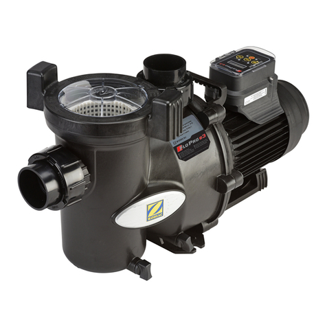
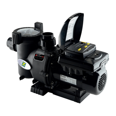
Zodiac FloPro VS User manual

H0448700.B - 2014/05
TM
Instruc ons for installa on and use
English
More documents on:
www.zodiac.com
EN

H0448700.B - EN - 2014-051
•Read this noce carefully before installing, maintaining or repairing this appliance!
•The symbol indicates important informaon that it is imperave to take into consideraon in
order to avoid all risks of harm to persons or damage to the appliance.
•The symbol indicates useful informaon.
Warnings
•As part of a connuous improvement process our products may be modied without prior noce.
•Exclusively for use as a circulaon/ltraon pump for pools only. This pump must not be used for any
other purpose.
•The appliance must be installed and serviced by a qualied technician in compliance with the
manufacturer’s instrucons and with applicable Naonal standards. The installer is liable for the
installaon of the appliance and the compliance with Naonal regulaons in maers of installaon.
Under no circumstances can the manufacturer be held liable in the event of failure to comply with
applicable Naonal standards.
•The installer must install a disconnect device which will allow disconnecon of all poles of the power
supply to the pump. Such means of disconnecons must be installed in the xed wiring to the appliance
in accordance with all applicable wiring rules.
•Incorrect installaon may cause damage to property or serious injuries (possibly causing death).
•It is important that this appliance is handled by skilled and apt persons (both physically and mentally),
with prior knowledge of the usage instrucons (by having read this manual). All persons not meeng
these criteria must not approach the appliance in order to avoid risk of electrical shock or other hazards
which could result in property damage or serious injury, including loss of life.
•If the appliance suers a malfuncon: do not try to repair the appliance yourself, contact your retailer.
•Disconnect all power to the appliance and ensure that the appliance is decommissionned prior to
aempng any service. Failure to do so can result in risk of electrical which can cause serious injury or
loss of life.
•Before any operaons check that:
-The voltage indicated on the appliance idencaon plate corresponds to the mains voltage,
-The power supply is suitable for use with the appliance, and that it has a ground connecon.
•Eliminang or shunng one of the safety devices automacally voids the warranty, as does the
replacement of parts using parts not originang from our stores.
•Keep the appliance out of the reach of children.
•This pump is compable with all types of pool water treatment. Please refer to the Zodiac® warranty
terms for the detail of admissible water balance values.
•Never run the pump without a water supply, or outside the water (this voids the warranty).

EN
H0448700.B - EN - 2014-05 2
Contents
1. Informaon before installing................................................................................................................... 3
1.1 General delivery terms and condions...................................................................................................... 3
1.2 Contents.......................................................................................................................................................... 3
1.3 Technical specicaons ................................................................................................................................ 3
2. Installaon....................................................................................................................................................... 3
2.1 Selecon of the locaon .............................................................................................................................. 3
2.2 Installing the appliance ................................................................................................................................ 3
2.3 Hydraulic connecons .................................................................................................................................. 4
2.4 Electric connecons ...................................................................................................................................... 4
3. Use....................................................................................................................................................................... 8
3.1 User interface presentaon......................................................................................................................... 8
3.2 Checks before starng up............................................................................................................................. 8
3.3 Start up the appliance .................................................................................................................................. 8
3.4 User interface sengs and use................................................................................................................... 9
4. Maintenance................................................................................................................................................. 15
4.1 Maintenance instrucons .......................................................................................................................... 15
4.2 Winterizing ................................................................................................................................................... 15
4.3 Recycling ....................................................................................................................................................... 15
5. Troubleshoong .......................................................................................................................................... 15
6. Registering the product............................................................................................................................ 16
Are available in the appendices at the end of these instrucons:
• Dimensions
• Descripon
• Performance graphs
• EC Declaraon of compliance

H0448700.B - EN - 2014-053
1. Informa on before installing
1.1 General delivery terms and condi ons
All equipment, even postage and packing paid, travels at the risks and perils of the recipient. Wri en reserves should be
made on the transporter’s delivery documents if damage during transport is discovered by the recipient (con rmed by
registered le er to the transporter within 48 hours).
1.2 Contents
x6
FloPro™ VS Bases Remote user interface kit Cable gland
x1 x2 x1 x1
1.3 Technical speci ca ons
• Power: 1.65HP - 1.2kW
• Opera on at from 600 to 3450 rpm (se ngs per 10 rpm step)
• Number of programmable speeds: 8
• Flow rate at 8 metres hydraulic head: 26m³/hr
• Opera ng temperatures: from 2 to 50°C air, and 2 to 35°C water
• Protec on index: IPX4
2. Installa on
2.1 Selec on of the loca on
• The pump must be installed:
-before the lter, the hea ng system, or the water treatment,
-at a minimum distance of 3.5 meters from the edge of the pool in order to avoid any projec ons of spray onto the
appliance. Some standards allow for other distances. Refer to the regula ons in e ect in the country of installa on.
-ideally 30 cm below the water level,
-outside areas liable to ooding, or on a base with drainage,
-in a ven lated zone to allow for cooling.
• The pump must not be installed:
-in an area subjected to water spray, rain, direct sunlight,
-at more than 3 metres above the water level,
-close to a heat source or to a source of in ammable gas.
• Install a check valve if the pump is installed above the water level.
• It must have easy access for any work to be carried out on the appliance.
• Use as few bends as possible.
2.2 Installing the appliance
• Install on a stable, solid (concrete slab for example) and level surface.
• If necessary, use the bases provided (one ne + intermediate blocks and one thick, use only one, or both combined) to raise
the pump to the level of the exis ng piping.
• Screw the pump (and the base(s) if applicable) to the ground using suitable lag-screws.
EN
H0448700.B - EN - 2014-05 4
2.3 Hydraulic connecons
1: pump
2: lter
3: heang system
4: water treatment system
Follow the hydraulic connecon direcon (see § “Sizes” in the appendix).
Pipe Maximum admission ow rate
1.8 metres/second
Maximum discharge ow rate at
2.4 metres/second
Ø 50 mm 14 m³/h 19 m³/h
Ø 63 mm 20 m³/h 27 m³/h
• Choose the piping size depending on the pool size and in compliance with locally applicable hydraulic rules.
• The performance graphs are available in the appendix for use in pipe sizing.
• The use of union ngs on the admission and discharge is recommended to make work on the appliance easier (the pump
admission and discharge have a 2’’ interior threading).
• If more than 10 bends are to be installed on the hydraulic circuit, increase the pipe diameter.
• Avoid high points to facilitate priming.
• Make sure the hydraulic ngs are correctly ghtened and that there are no leaks.
• The pipes must be supported to avoid any risk of breakage due to the weight of the water.
2.4 Electric connecons
• The pump will only start when commanded by its user interface or an external controller (AquaLink® TRi for example).
• Risk of electric shocks that can result in serious injury or loss of life. Only a qualied and experienced technician
is authorized to wire inside the appliance.
• It is imperave to connect the appliance to an earth rod.
• Connect the pump so that the general power supply is never inadvertently interrupted when a speed is being
used. The speeds are monitored and controlled by the pump user interface and the on-board motor drive
controller, not by any other means in the mains power supply (see §3.4.4 for pump mer operaon). An
improper electric connecon voids the warranty.
• Loose terminals can cause the terminal block to heat and lead to the warranty being voided.
• If the power supply cable is damaged it should be replaced by a qualied technician.

H0448700.B - EN - 2014-055
2.4.1 Voltage and protec on
• Electric protec on: use a circuit breaker (D curve) or a fuse (aM) (calibre 16A minimum), with a speci c 30 mA Residual
Current Device (RCD) or Ground Fault Circuit Breaker (GFCB) at the head of the line (circuit breaker or switch).
• The appliance, the pool, and all other electric equipment must be connected to the ground.
Acceptable voltage varia on: +/-10% (when running).
2.4.2 Connec ng the motor power supply
• Open the electric box in front of the user interface by removing its screw and li ing it.
• Connect the power supply cable to terminals L1-L2 (or L-N) and (ground).
• Power supply cable size: for a maximum length of 45 metres (calcula on on the basis of: 5A/mm²), must be checked and
adapted to installa on condi ons.
• Electrical speci ca ons
Voltage Full load current Cable cross sec on Electric protec on
Amm² Type A
230V-50Hz 5.22 3x1.5 3G1.5 16
2.4.3 User interface connec on op ons
• In order to avoid risk of electrocu on, which can result serious injury or loss of life, be sure to disconnect all
power at the source before proceeding with the instruc ons below.
• Connec on to an RS485 terminal block: 1 = red; 2 = black; 3 = yellow; 4 = green
• Do not cut the RS485 cable as this will result in not being able to reconnect the user interface to the pump and
will make it impossible to reset the factory se ngs. The cable is xed to the pump and cannot be removed or
extended.
a) Default connec on
• The user interface is xed and wired to the pump in the factory.
• The pump communicates with its user interface using an RS485 cable (4 wires) (C).
Switch posi on 12345
For control using the user interface on on o o on
A: pump electric compartment
B: pump RS485 terminal block
C: RS485 pump cable
D: user interface
E: user interface terminal block

EN
H0448700.B - EN - 2014-05 6
Step 1:
• Open the electric compartment (A) in front of the user
interface (D) by removing its screw and liing the cover.
• Unscrew the 6 screws that hold the interface (D) to the
pump.
• Unscrew the 4 wires from the user interface terminal block
(E).
Step 2:
• Disconnect the RS485 terminal block (B) and put it aside.
• Unscrew the cap (L) and install a cable gland (not supplied)
to take the cable RS485 (G) out of the electric compartment.
• Plan the correct length of cable for the extension (G) and
connect it to the RS485 terminal block (F), then connect to
the electric compartment (A).
Step 3:
• Fit the base and the foam seal (H) on the user
interface locaon on the pump using the 6 screws
(I).
Step 4:
• Drill a hole at the posion marked in the centre of
the base (J) and install the grommet (K).
• Aach the base (J) onto a stable wall (using screws
adapted to suit the base, not included), away from
humidity and direct sunlight.
• Connect the other end of the RS485 cable (G) to the
user interface terminal block (E).
• Aach the user interface (D) to the base (J) using its
6 screws.
Kit contents:
x6
Kit RS485 terminal block Kit RS485 extension cable Pump base + foam seal Screws User interface base Grommet
FGHIJK
b) Remote user interface opon
• This interface can be installed in another locaon using the supplied remote kit.
• In order to avoid risk of electrocuon, which can result serious injury or loss of life, be sure to disconnect all
power at the source before proceeding with the instrucons below.
• Connecon to an RS485 terminal block: 1 = red; 2 = black; 3 = yellow; 4 = green
• Do not cut the RS485 cable as this will result in not being able to reconnect the user interface to the pump and
will make it impossible to reset the factory sengs. The cable is xed to the pump and cannot be removed or
extended.
• Never lay these low-voltage cables in the same pipe as high-voltage cables.
Pump descripon:
A: pump electric compartment
B: pump RS485 terminal block
C: pump RS485 cable
D: user interface
E: user interface RS485 terminal block
L: removable cap for the cable pass-thru locaon

H0448700.B - EN - 2014-057
2.4.4 External “on/o ” switch connec on op on
• You can connect to an external dry contact (B) to ac vate or deac vate a speed n the case of a backwash or the use of a
booster pump.
To connect this func on the user interface must be remote in order to pass the wire through the base cable pass-thru
(see procedure §2.4.3.b).
In the case of connec on to an external controller, the func on will be proposed automa cally.
• Access the electronic card on the back of the user interface (A).
• Connect the contact to the 2 terminals on the J3 connector: COMMON + INPUT1, 2, 3 or 4 depending on the speed you
require to ac vated using the contact (INPUT1 = speed 1, INPUT 2 = speed 2, INPUT3 = speed 3, INPUT4 = speed 4).
• When the contact is closed, the regula on interface will display: and the pump
will start at the speed selected on the J3 connector.
• Speed 4, by default known as «booster pump», is equipped with a 30-minute mer. When the contact is opened, a
countdown is displayed:
c) AquaLink® TRi connec on op on
• In order to avoid risk of electrocu on, which can result serious injury or loss of life, be sure to disconnect all
power at the source before proceeding with the instruc ons below.
• Connec on to an RS485 terminal block: 1 = red; 2 = black; 3 = yellow; 4 = green
• Do not cut the RS485 cable as this will result in not being able to reconnect the user interface to the pump and
will make it impossible to reset the factory se ngs. The cable is xed to the pump and cannot be removed or
extended.
• Never lay these low-voltage cables in the same pipe as high-voltage cables.
• Open the electric compartment in front of the user interface by removing its screw and li ing the cover.
• Disconnect the RS485 terminal block and put it aside.
• Connect the supplied RS485 cable extension between the AquaLink® TRi and the pump using the RS485 terminal blocks.
Switch posi on 12345
For control using the AquaLink® TRi o o o o on
• Refer to the AquaLink® TRi installa on and user manuals to declare the pump
and launch it.
The user interface is deac vated when the pump is connected to the AquaLink® TRi.

EN
H0448700.B - EN - 2014-05 8
3. Use
3.1 User interface presentaon
Symbol Descripon
Menu access buon
Validate a selecon
Preset “eStar”speed buon (1750 rpm)
Back buon for a sub-menu
Preset speed buons
Rotaon speed change buons
Menu navigaon key (pressing connuously scrolls the
values increasingly quickly)
Display: pump o
Operaon to carry out to acvate a speed
Time Pump status
Display: pump on
Name of the acve speed
Time Pump speed
RPM = rotaons per minute
↕ = indicates that it is possible to increase or lower the speed in steps of 10 using the and keys.
If the language displayed on the screen are not appropriate, see §3.4.3.d.
3.2 Checks before starng up
• Check that the hydraulic connecons have been correctly ghtened.
• Make sure the pump is stable, it must be level and at.
• The electric cable must be routed away from sharp or hot items that could damage it.
• The plumbing system must be drained and must not contain any debris.
• The pump basket cover must be correctly closed (manually) and its seal must be clean and in place.
• Make sure the valves are open.
• In order to prevent risk of explosion which can cause property damange and serious injury, including loss of life,
ensure that the plumbing system is cleared of any debris or blockages and is not subjected to excess pressures.
• Never run the pump “dry”, as this could risk damaging it.
• The basket cover must be closed manually (do not use tools).
3.3 Start up the appliance
• Start a speed, the pump always starts in “priming” mode (high speed).
• The pump is self priming. However, it is strongly recommended to ll the basket with water before starng up for the rst
me to facilitate the procedure.
• Purge any air that may be present in the ltering circuit using the purge that is normally on the lter (refer to the pool lter
manual).
• The default priming speed is 2750 rpm, the mode runs for 3 minutes.
• To change the speed and/or ming, refer to §3.4.5.c.
• Check that there are no leaks on the hydraulic circuit.
The pump has a priming capacity up to 3 metres above the pool water level (if the hydraulic circuit is perfectly sealed).

H0448700.B - EN - 2014-059
3.4 User interface sengs and use
The user interface has a baery to keep the me and saved sengs in memory when the pump is no longer connected to the
electricity supply.
3.4.1 Locking/unlocking the keyboard
Press and for 5 seconds: displays as long as the keyboard is locked. To
unlock, press and for 5 seconds, the message disappears.
3.4.2 Starng or stopping a speed
Speed Keys to start or stop a speed Default speed
“eStar”speed 1750 rpm
Speed 2 2750 rpm
Speed 3 2750 rpm
Speed 4 2750 rpm
Speed 5, 6, 7 or 8 then or then to validate 2750 rpm
• When the pump is running it displays (speed n° and name, me, operang
speed), and a led lights over the key corresponding to the speed.
• For speeds 2, 3, 4, 5, 6, 7 and 8, you can modify the default speed by pressing or when the speed is running (from
600 to 3450 rpm). When a modicaon is made, it is saved automacally.
• To set the default “eStar”speed, please refer to §3.4.5.d.
• To stop the pump, press the key for the current speed ( , , or ), or on (speeds 5, 6, 7 or 8).
3.4.3 User menu
To access the user menu when the pump is stopped, press for 5 seconds:
To scroll through the menu, use the or keys.
To exit the menu, press , or refrain from any acon for 1 minute.
a) Set the me
The me must be set to be able to use the “Timer” funcon.
AM = before noon (ante meridiem)
PM = aer noon (post meridiem)
press to access the seng:
press or to set the me (minute by minute), then validate by pressing
.

EN
H0448700.B - EN - 2014-05 10
b) Label speeds
Used to associate a name with a pre-programmed speed.
press to access the seng :
select the speed number you want to label using or , then press
to validate:
or
The “General” seng proposes a list of pre-dened labels: Filtraon, Cleaning, Spa, Spa jets, Heang, Waterfall, Sheer descent
(= water blade) or water feature.
The “Custom” seng allows to enter labels. To do this, modify the ashing character using the or keys, validate the
character and move on to the next by pressing .
The key is used to go back to the previous character.
To validate the label, the enre line must be lled, then press to validate.
c) Display lighng
Used to adjust the screen back-lighng.
press to access the seng:
choose the required seng and press to validate:
2 min meout Turns o the back lighng aer the user interface has been idle for 2 minutes
Light o No screen back lighng
Light on Screen back lighng always on
d) Language
Used to choose the interface language.
press to access the seng:
choose the required language (French, English, Spanish, Deutsch, Nederlands or
Italiano), then press to validate.
e) Run duraon
Used to determine how long the speed will run for a manual launch (no Timer), only available for speeds 3 and 4.
press to access the seng:
choose the required speed and press to validate:
set the operang me using keys or (up to 8 hours in 30 minute steps),
validate by pressing .

H0448700.B - EN - 2014-0511
f) Password protecon
Used to protect access to the user menu using a 4 digit password.
This protecon will only acvate aer the user interface has been idle for 10 minutes
press to access the seng:
choose the required funcon and press to validate:
No No password protecon, the user menu remains accessible to the user
Yes Password protecon acvated
Change the ashing number using the or keys, validate the number and move to the next by pressing .
The key is used to go back to the previous number.
To validate the password, ll in the 4 numbers and press to validate:
To deacvate the password, return to the seng by pressing to access it:
choose the required funcon and press to validate:
No The password remains unchanged and acve
Clear Deacvates the password
Change Used to modify the password
3.4.4 Timeclock
“Timers” (= named “Timeclock”, used to programme pump starng and stopping mes) can be programmed for
speed 2 and “eStar”.
The “Timers” operate in the same way every day of the week.
In order to prevent the risk of property damage or injury, it’s strongly recommended to use “Timers” when the
pump is not controlled externally so that the pump does not acvate any speeds when power is restored aer
being interrupted.
To access the “Timeclock” menu, “eStar”or speed 2 must be running (depending on the speed you want to programme):
Press :
Press to acvate or desacvate the programming: , then press to
validate.
Press to set the speed starng me using keys or , then press
to validate.
Next set the speed stopping me in: , then validate by pressing .
Press to exit from the menu.

EN
H0448700.B - EN - 2014-05 12
• When the pump is running on a Timer, the led corresponding to the speed lights red and a clock appears on the screen:
.
• When the pump is not running but a Timer is acve, the led corresponding to the speed lights in green.
• 2 Timers can be acvated at the same me. The highest speed Timer will have priority.
• The pump can be stopped manually when a Timer is running by pressing the buon for the acve speed. The Timer will
resume its normal acvity on the next cycle.
• If the pump is started manually and a Timer is acve, it will stop at the end of the programmed Timer.
• To deacvate an acve Timer, go to , then press to validate.
3.4.5 Service menu
To enter the service menu the pump must be stopped.
Press , and at the same me for 5 seconds: .
To scroll through the menu, use the or keys.
To exit the menu, press , or refrain from al acon for 1 minute.
a) Load defaults
Used to reset the factory sengs.
Seng By default Possible values
“eStar”speed 1750 rpm
from 600 to 3450 rpm, per 10 rpm stepSpeed 2, 3, 4, 5, 6, 7 and 8 2750 rpm
Priming speed 2750 rpm
An-freeze protecon me 30 minutes from 0 to 8 hours, per 30 minute step
Priming me 3 minutes from 1 to 5 minutes, per 1 minute step
press to access the seng:
press or to select “yes”, then press to validate, your user interface
will have the factory sengs.
b) Last fault
Used to view the 2 last pump faults.
press to access the seng:
The screen will display the latest error messages. If there are none in memory *-------* will be displayed.
To delete the messages, press or .

H0448700.B - EN - 2014-0513
c) Priming
Used to set the pump priming speed.
A priming speed greater than 2500 rpm is strongly recommended in order for it to be eecve.
press to access the seng:
press to change the priming speed:
use the or keys to set the speed (from 600 to 3450 rpm, per 10 rpm step),
then press to validate.
Press or to access the seng press to modify the priming me:
use keys or to set the me (from 1 to 5 minutes, per 1 minute step), then
press to validate.
The user interface displays: / when the
pump is in the priming cycle.
d) Set “eStar”speed
Used to dene the pre-set “eStar”speed (by default known as «1: Filtraon»).
press to access the seng:
use the or keys to set the speed (from 600 to 3450 rpm, per 10 rpm step),
then press to validate.
e) Pump freeze protect
The pump measures the running motor temperature and esmates the water temperature.
It acvates the “eStar”speed if the temperature is too low, to protect the pump from freezing. This seng is used to
set the an-freeze cycle me.
Freeze protecon is intended to protect equipment and plumbing for short periods of freezing only. It does this by
acvang the ltraon pump and circulang the water to prevent freezing inside equipment or plumbing. Freeze
protecon does not guarantee that equipment will not be damaged by extended periods of freezing temperatures
or power outages. In these condions, the pool should be shut down completely (for example, drained of water
and closed for the winter) unl warmer weather exists.
The pump must be protected and properly winterized when freezing temperatures are expected. Allowing the
pump to freeze will cause severe damage and will void the warranty.
press to access the seng:
use the or keys to set the me (from 0 minutes to 8 hours, per 30 minute
step, then press to validate.
To deacvate the funcon, set the me to “0:00”.

EN
H0448700.B - EN - 2014-05 14
f) Pump type
This seng is used to determine the maximum authorised pump speed depending on the selected type.
It is recommended not to change this seng to keep opmum pump performances.
press to access the seng:
use the or keys to select “ePUMP 60Hz” (maximum speed by default = 3450
rpm) or “ePUMP 50Hz” (maximum speed by default = 2850 rpm), then press to validate.
g) Display power usage
You can display the pump’s electricity consumpon while running (in Was).
This seng is only displayed on the screen when the pump is running.
press to access the seng:
use keys or to select “YES” or “NO” then press to validate.
To deacvate the funcon press “NO”.
When the funcon is acve, the user interface alternavely displays: and
h) Set minimum limit
This is used to limit the pump’s minimum operang speed. The user will no longer be able to set the pre-dened
speeds 2, 3, 4, 5, 6, 7 and 8 slower than this speed. The default speed is 600 rpm.
press to access the seng:
use the or keys to set the speed (from 600 to 3450 rpm, per 10 rpm step),
then press to validate.
i) Set maximum limit
This is used to limit the pump’s maximum operang speed. The user will no longer be able to set the pre-dened
speeds 2, 3, 4, 5, 6, 7 and 8 faster than this speed. The default speed is 3450 rpm.
press to access the seng:
use the or keys to set the speed (from 600 to 3450 rpm, per 10 rpm step),
then press to validate.

H0448700.B - EN - 2014-0515
4. Maintenance
4.1 Maintenance instrucons
It is recommended to carry out general servicing of the appliance on winterizing and restarng in order to check
it is in good working order and maintain its performances, as well as to prevent certain possible defects.
These acons are the user’s responsibility and must be carried out by a qualidied technician.
• Make sure no foreign bodies enter the pump or the electric compartment.
• Clean the outside of the appliance, do not use solvent based products.
• Check that the use interface is in working order.
• Check that metal casing is connected to the ground.
• Check the ghtness of the electric wire connecons and the cleanliness of the electric control box.
• Clean the basket, the lid and its seal regularly.
• Make sure the basket is correctly ed, otherwise it could prevent the hermec closure of the lid.
4.2 Winterizing
Freeze protecon is intended to protect equipment and plumbing for short periods of freezing only. It does this by
acvang the ltraon pump and circulang the water to prevent freezing inside equipment or plumbing. Freeze
protecon does not guarantee that equipment will not be damaged by extended periods of freezing temperatures
or power outages. In these condions, the pool should be shut down completely (for example, drained of water
and closed for the winter) unl warmer weather exists.
The pump must be protected and properly winterized when freezing temperatures are expected. Allowing
the pump to freeze will cause severe damage and will void the warranty. To avoid condensaon damaging the
appliance, do not cover it hermecally.
• If the pump is located beneath the water level, shut o the isolaon valves on the admission and discharge.
• Drain the pump (using the 2 drainage screws) and the hydraulic circuit by following the pool manufacturer’s instrucons.
• Remove the 2 drainage screws and put them aside to be reed when the pool is restarted.
• It is recommended to disconnect the electric power cable, and then to unscrew the hydraulic ngs to store the pump in
a dry locaon protected from freezing.
4.3 Recycling
This symbol means that your appliance must not be disposed of as household waste. It will be selecvely collected
with a view to its reuse, recycling or the sale of the parts. If it contains substances potenally dangerous to the
environment, these will be eliminated or neutralised.
Ask your retailer for informaon about recycling.
5. Troubleshoong
Malfuncon Possible causes Soluons
The water is not
circulang properly • Dirty basket and/or lter
• Incorrectly set valves • Clean the basket and/or lter
• Adjust the valves
There are air bubbles
in the basket • Air is blocked in the circuit
• The pool water level is too low
• The pump lid is incorrectly sealed
• Purge the circuit
• Check the water level, add water if necessary
• Check the cover and seal are airght
There are air intakes • The ngs are not properly ghtened
• The ng seals are incorrectly
posioned or damaged
• Tighten the ngs
• Change the seals
There is no air in
the circuit but the
pressure is low
• There is debris stuck inside the pump • Remove the debris manually by opening the lid
and removing the basket
• If debris remains, the pump will need to be
dismantled to access the impeller
• Warning: these operaons must be carried out by
a qualidied technician
If there is no debris
in the pump but the
pressure is low
• The pump impeller and diuser are
worn
• Electric problem
• Worn seal
• Have the impeller and diuser replaced by a
qualidied technician
• Have the electric installaon checked by a
qualidied technician
• Replace the seal
There is a water leak
between the motor
and the pump body
• The mechanical packing is damaged or
defecve • Replace the mechanical packing
• Warning: these operaons must be carried out by
a qualidied technician

EN
H0448700.B - EN - 2014-05 16
Malfunc on Possible causes Solu ons
The pump heats and
some mes switches
o
• Bad air circula on around the motor
• Bad electric connec ons
• Current varia ons are too high
• Check that the motor is correctly ven lated for
cooling
• Check the electric connec ons
• Have the electric circuit checked by a qualidied
technician
The pump will not
start • There is no power supply to the pump
• The user interface cable is damaged
• The pump address is incorrectly
con gured
• The user interface displays an error
message
• Check the electric connec ons
• Check the condi on of the user interface cable
• Check the switch con gura ons (see §2.4.4)
There is nothing on
the user interface or
the external controller
display
• The pump address is incorrectly
con gured
• The user interface cable is damaged
• Check the switch con gura ons (see §2.4.4)
• Check the condi on of the user interface cable
The user interface
displays "PUMP NOT
CONNECTED"
• The user interface cable is damaged
• The pump address is incorrectly
con gured
• Check the condi on of the user interface cable
• Check the switch con gura ons (see §2.4.4)
6. Registering the product
Register your product on our website: www.zodiac.com
-You will be the rst to be informed of new Zodiac® products and special o ers,
-You can help us to constantly improve our product quality.

H0448700.B - EN - 2014-05
Dimensions
Weight pump only : 17kg
Descripon
AWater admission
BWater discharge
CPre-lter cover
DUser interface
EPump motor
FDrain
Performance graphs
Hydraulic head
Flow

Notes

Zodiac Pool Care Europe - BP 90023 - 49180 St Barthélémy d’Anjou cedex - S.A.S.U. au capital de 1 267 140 € / SIREN 395 068 679 / RCS PARIS
Pour plus de renseignements, merci de contacter votre revendeur.
For further informa on, please contact your retailer.
ZODIAC® is a registered trademark of Zodiac Interna onal, S.A.S.U., used under license.
Votre revendeur / your retailer
www.zodiac.com
Other manuals for FloPro VS
1
Table of contents
Other Zodiac Swimming Pool Pump manuals
Popular Swimming Pool Pump manuals by other brands

laguna
laguna Powerjet 1500 Installation and maintenance guide

Aquant
Aquant BLM200 Installation and operation manual

Pentair Pool Products
Pentair Pool Products SuperFlo brochure

Bestway
Bestway 58230 owner's manual

Wayne
Wayne WAPC250 Operating instructions & parts manual

Shott
Shott WP14000 Customer's manual