SpaNet SMARTFLO SC05 User manual

instruction manual
WARNING - Safety Instructions
Read and follow all instructions before installing this product. Failure to follow warning
notices and instructions may result in property damage, serious bodily injury or death.
This product must be installed and serviced by a person who is knowledgeable and
qualified in pool or spa plumbing and equipment by the jurisdiction in which the
product will be installed.
!

SAFETY WARNINGS - Risk of Electrical Shock
ŸThe pump must be installed in a weatherproof enclosure such as under a spa skirt. The pump
should be installed in an enclosure such that all electrical connections cannot be accessible to
the user without the use of a tool.
Ÿ Power connections and wiring must be carried out by a licensed electrician. In all cases
conform to all national, state and local wiring rules and/or codes of electrical practice in effect
at the time of installation.
ŸThe appliance must be connected to a suitable rated and weather protected power supply.
Means for disconnection must be incorporated in the fixed wiring in accordance with your
local wiring regulations, to allow disconnection of the appliance from the supply after
installation. Means for disconnection from the supply mains should have a contact separation
in all poles that provide full disconnection under over voltage Category III conditions.
Ÿ Ensure that an electrical isolation switch is located with easy access so that the pump can be
switched off in an emergency.
ŸThis is a Class 1 appliance and must be connected to protective earth.
ŸThis appliance should be supplied through a residual current device (RCD) having a rated
residual operating current not exceeding 30mA.
ŸRefer to AS3000 wiring rules (Aust. & NZ) and IEC60364 Part 7 (Europe) or equivalent for
guidance with compliance to the wiring codes for wet area and equipotential bonding.
ŸIf the supply cord is damaged it must be replaced by the manufacturer, its service agent,
licensed electrician or similarly qualified persons in order to avoid a hazard.
ŸNo part of this appliance is to be located directly above the spa pool and must be inaccessible
to a person in the spa pool. All parts must be fixed so they cannot fall into the spa pool.
Ÿ DANGER! Pump suction is hazardous and can trap and drown or disembowel bathers.
Do not block suction points. Do not use or operate swimming pools, spas or spa baths if
a suction cover is broken, missing or loose. Two suction covers and inlets must be
provided into every pump to avoid suction entrapment.
Ÿ If the pump is located below water level, it is recommended to fit isolating valves in the pipe
work between the pump and the suction inlet and in the return pipe from the pump to the
pool.
ŸThis appliance is not intended for use by persons (including children) with reduced physical,
sensory or mental capabilities, or lack of experience and knowledge, unless they have been
given supervision or instruction concerning use of the appliance by a person responsible for
their safety.
ŸChildren should be supervised to ensure they do not play with the appliance.
!

General Information
This manual has been constructed to offer the adequate information on the installation,
operation and maintenance of our spa pool pumps. We suggest you read it thoroughly for
correct installation and optimum performance of the pump.
These are single-stage centrifugal pumps designed to operate with hydro-massage
equipment on spa pools. They should not be used for any other purpose without first
consulting your SpaNET dealer or Spa Net Customer Service. The pumps are designed to
o
operate with clean water at a maximum water temperature of 50 C.
Installation Location
ŸThe pump should be located as close to the water as practical keeping the suction pipe
of the pump as short as possible.
ŸThe pump should be installed on a level firm base in a well drained position, high
enough to prevent any flooding and be fixed to the base by screws or nuts.
ŸIt is the installer’s responsibility to position the pump so that the ratings label can be
easily read for service, and in a location where water will not drip onto the motor.
ŸThe pump will get hot during operation, to ensure sufficient cooling the minimum
distance between the motor of the pump and any surrounding structure should not be
less than 30mm.
Pipe Connection
ŸThe suction pipes should have a diameter equal to or larger than that of the discharge
pipes, to avoid loss of head and improve pump efficiency.
ŸTwo suction inlets must be provided into each pump to avoid suction entrapment.
ŸSuction & discharge pipes should have a gentle slope of at least 2% to assist purging air.
Suction Pipe with two inlets
Installation Diagram
Minimum water level for pump operation
Discharge Pipe Isolation Valves

Pipe Connection (continued)
ŸThe maximum inlet water pressure ≤ 0.15MPa
ŸA set of mac unions are provided for connecting the pump to the pipe work. The circ
pump series are designed to accept 40mm PVC pressure pipe, the boost pump series
accept 50mm PVC pressure pipe.
ŸThe use of PVC pressure pipe smaller than 40mm (circ series) or 50mm (boost series) is
not recommended.
ŸThe pipe work should be adequately supported and secured to the mac union by glueing
the pipe to the inside of the union tail.
ŸMac union lock nuts are to be hand tightened. Do not use sealant, silicones or glues on
lock nuts.
Power Connection
ŸSpaNET SmartFLO pumps are suitable for connection to a nominal 240V AC / 50Hz power
supply and are supplied with a flexible lead and AMP plug to facilitate easy connectivity
to a SpaNET spa controller.
ŸThis pump should be supplied through a residual current device (RCD) having a rated
residual operating current not exceeding 30mA.
ŸAll SmartFLO pump motors have built-in thermal protection.
ŸWires serving as equipotentional bonding conductors shall have a cross sectional area
2 2
between 2.5mm and 6mm and be equipped with suitable terminal receptacles.
ŸExtension power cords are unsafe around spas and pools and should not be used.
Steps prior to starting pump
Before attempting to use the pump you must confirm that:
ŸThe pump has been installed in a safe and dry environment.
ŸThe enclosure that houses the pump has sufficient drainage in the event of leakage
ŸVerify that the pump shaft turns freely.
ŸCheck the mains voltage and frequency of power supply match ratings label of pump.
ŸThe pipe work is correctly supported and barrel unions are tight and sealed.
ŸThe spa pool water level is at the correct height and the pump has been primed.
ŸAll isolating valves are open and there is nothing preventing flow of water into and out of
the pump.
WARNING: The pump should never be operated dry!
Running the pump without water may damage the mechanical seal causing the pump
to leak. Damage to seals from dry running of the pump is NOT covered by warranty.
!

Pump Operation
ŸTo assist in priming, the pump should always be located below the water level of the spa.
ŸFollow tips in “Steps prior to starting pump” before switching pump on.
ŸConnect the pump to spa controller or power supply and turn on.
ŸAllow the pump to run to expel any air that may be trapped in the pump wet end.
ŸIf full prime is not achieved within 30-40 seconds (full prime will be demonstrated by a
strong flow of water returning to the spa), switch off the pump and wait for 30 seconds
before trying to operate the pump again
ŸIf the pump does not fully prime after 3 attempts, the pump should be switched off and
pump should be bled of air manually by slightly loosening barrel unions to expel the air,
and after the air is bled the pump can be operated again.
Water Chemistry Maintenance
Avoiding over sanitising and maintaining balanced water chemistry is very important to the
life span of your SmartFLO pump. It is your responsibility to regularly check and maintain the
chemical water balance of the spa pool (at least once a week), to ensure it remains within
reasonable pH and Alkaline limits. The pump is designed to be used with balanced spa water
with a pH level of between 7.2 - 7.8 pH, and is to be regularly treated with a sanitising agent
with a level not exceeding 3PPM. Please visit your local pool and spa shop for regular water
tests and for further guidance regarding water chemistry.
NOTE: Do not add raw undiluted chemicals directly to the spa filter area or near the
pump suction drains. Adding undiluted chemicals may damage the pump and
mechanical seal and void warranty.
Maintenance & Cleaning
ŸEnsure that suction covers are securely attached and not damaged or broken. Do not
operate pump if suction covers are broken to avoid entrapment.
ŸRemove any debris or obstructions that may build up on suction covers.
ŸEnsure filters are regularly cleaned and soaked in filter cartridge cleaner every 4-6 weeks.
ŸCheck water balance and sanitiser levels on a regular basis
ŸEvery 12-18 months inspect pump for leaking mechanical seal. If seal is leaking ensure
pump is serviced and mechanical seal is replaced. If the seal is leaking and it is not
replaced, the leak will eventually cause the bearings to rust and seize the motor.
ŸIf the pump is to be idle for a long period of time, it is recommended to disconnect both
suction and discharge barrel unions, drain the water from the pump wet end and leave
unions disconnected so the pump is dry and well ventilated.
!

Troubleshooting
Pump not pumping properly / water flow reduced
ŸPump is not primed and wet end full of air - attempt to reprime pump and/or bleed air
from pump by loosening barrel unions.
ŸPump is starving for water - check the valves to the pump are open fully, check water
level - top up if necessary, check spa filter cartridges and clean if required.
ŸThere are air leaks in the suction line - check all pipe work and tighten mac unions to
eliminate leaks.
ŸA leaking mechanical seal may also cause problems with the pump bearings and make it
difficult for the pump shaft to rotate - water or chemical calcification will be evident
underneath the pump if the seal has been leaking. Service pump in this case.
ŸImpeller is worn out - service pump and replace impeller
Pump does not start
ŸThe power cord is not connected - check power cable. Where the pump is connected to a
spa controller check the pump is connected to the correct pump socket, check dip
switches are set correctly, and check controller touch pad to confirm pump is active.
ŸLow voltage - check there is proper voltage applied to the pump and avoid using
extension cables.
ŸBlockage in pipe work or pump wet end in preventing the pump from rotating - inspect
for foreign debris and remove where required.
ŸMotor has overheated and thermal cut-out has activated - the pump motor has built in
thermal protection which activates when the motor becomes too hot and automatically
resets after the motor has cooled. Determine the cause of overheating and rectify - check
motor has adequate ventilation, fan is not blocked and can spin freely.
ŸMotor has seized bearings due to a leaking mechanical seal over an extended period of
time - get bearing and seal service if possible, if not replace pump.
If you are unable to resolve any installation or operating issues with your SmartFLO pump
you should contact the reseller you purchased the pump from or your closest authorised
SpaNET repair technician or spa dealer. If you require any further assistance contact the
SpaNET Customer Service Department on +61 2 4587 7766 or [email protected]

Pump Dimensions
MODEL A B C D E F G H
INLET/OUTLET
PVC
NET WEIGHT
(kg)
SC05 73 134 182.5 202.5 106 85 275 363 5.8
SC10 73 134 182.5 202.5 106 85 275 363 7.3
40/40
DIMENSIONS (mm)
A
B
CD
E
F
G
H
MODEL A B C D E F G H
INLET/OUTLET
PVC
NET WEIGHT
(kg)
SB15 105 160 226 266 120 100 351.5 430 10.9
SB20 105 160 226 266 120 100 351.5 430 12.7
SB25 105 160 226 266 120 100 351.5 430 14.1
SB30 105 160 226 266 120 100 351.5 466 15.2
SB15-2S 105 160 226 266 120 100 351.5 480 14.1
SB20-2S 105 160 226 266 120 100 351.5 480 15.0
SB25-2S 105 160 226 266 120 100 351.5 480 17.2
SB30-2S 105 160 226 266 120 100 351.5 480 18.2
SB30-3P 105 160 226 266 120 100 351.5 466 14.7
DIMENSIONS (mm)
50/50
A
B
C
D
E
F
G
H
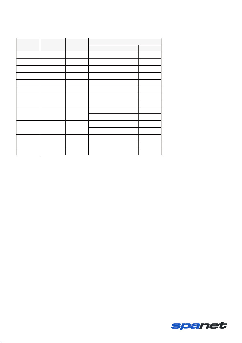
kW HP
SC05 220 7.5 0.35 0.5
SC10 365 9.5 0.75 1.0
SB15 560 13 1.10 1.5
SB20 690 14 1.50 2.0
SB25 760 15 1.85 2.5
SB30 790 15 2.10 3.0
(low speed) 0.3 0.4
(high speed) 1.1 1.5
(low speed) 0.35 0.5
(high speed) 1.5 2.0
(low speed) 0.35 0.5
(high speed) 1.85 2.5
(low speed) 0.45 0.6
(high speed) 2.1 3.0
SB30-3P 760 15 2.1 3.0
Power
MODEL
Qmax
(L/min)
Hmax
(m)
SB15-2S
560
13
SB30-2S
790
15
SB20-2S
690
14
SB25-2S
760
15
Pump Specifications
Contact Details
Spa Net Pty Ltd
4/103 Railway Road North
Mulgrave NSW 2756
Australia
Phone: +61 2 4587 7766
Fax: +61 2 4587 8766
www.spanet.com.au
Technical Support & Service [email protected]
Accounts Department [email protected]
Sales Department [email protected]
This manual suits for next models
10
Table of contents
Popular Swimming Pool Pump manuals by other brands


Intex
Intex Krystal Clear 634RC owner's manual

Pentair
Pentair 5P2R Installation and operating instructions

Evolution Aqua
Evolution Aqua UniTech Perfect 5000 operating instructions

Intex
Intex Krystal Clear C600 owner's manual

Hayward
Hayward SP2305X7 owner's manual

WPool
WPool WPS60 Installation and user guide