Calpeda MPC User manual

Pompe autoadescanti per piscine
Self-priming swimming pool pumps
Selbstansaugende Schwimmbadpumpen
Pompes autoamorçantes pour piscines
Bombas autoaspirantes para piscinas
Själv-evakuerande poolpumpar
Zelfaanzuigende zwembadpompen
ë‡ÏÓÁ‡ÎË‚‡˛˘ËÂÒfl ̇ÒÓÒ˚ ‰Îfl ·‡ÒÒÂÈÌÓ‚
自吸式泳池泵
MPC
ISTRUZIONI ORIGINALI PER L’USO Pagina 2 Italiano
OPERATING INSTRUCTIONS Page 10 English
BETRIEBSANLEITUNG Seite 18 Deutsch
INSTRUCTIONS POUR L’UTILISATION Page 26 Français
INSTRUCCIONES DE USO Página 34 Español
DRIFT/INSTALLATIONSANVISNINGAR Sidan 42 Svenska
BEDIENINGSVOORSCHRIFT Pagina 50 Nederlands
àÌÒÚÛ͈ËË ÔÓ ˝ÍÒÔÎÛ‡Ú‡ˆËË ëÚ. 58 êÛÒÒÍËÈ
安装使用手册 页码 66 中文
MPC Rev17.indd 1 29/08/17 11:59

GB
Page 10 / 80 MPC Rev17 - Operating Instructions
THIS INSTRUCTION MANUAL IS THE PROPERTY
OF CALPEDA S.P.A. ANY REPRODUCTION, EVEN
IF PARTIAL, IS FORBIDDEN
1. GENERAL INFORMATION
Before using the product carefully read the information
contained in this instruction manual, the manual should
be kept for future reference.
Italian is the original language of this instruction
manual, this language is the reference language in
case of discrepancies in the translations.
This manual is part of the essential safety requirement
and must be retained until the product is nally de-
commissioned.
The customer, in case of loss, can request a copy
of the manual by contacting Calpeda S.p.A. or their
agent, specifying the type of product data shown on
the label of the machine (see 2.3 Marking)
Any changes, alterations or modications made to the
product or part of it, not authorized by the manufacturer,
will revoke the “CE declaration” and warranty.
This appliance should not be
operated by children younger
than 8 years, people with reduced
physical, sensory or mental
capacities, or inexperienced
people who are not familiar with
the product, unless they are given
close supervision or instructions
on how to use it safely and are
made aware by a responsible
person of the dangers its use
might entail.
Children must not play with the
appliance.
It is the user's responsibility to
clean and maintain the appliance.
Children should never clean or
maintain it unless they are given
supervision.
Read carefully the installation
section which sets forth:
- The maximum permissible
structural working pressure
(Chapter 3.1).
- The type and section of the
power cable (Chapter 6.5).
- The type of electrical protection
to be installed (Chapter 6.5).
1.1. Symbols
To improve the understanding of the manual, below are
indicated the symbols used with the related meaning.
Information and warnings that must be
observed, otherwise there is a risk that the
machine could damage or compromise
personnel safety.
The failure to observe electrical information
and warnings, could damage the machine or
compromise personnel safety.
i
Notes and warnings for the correct management
of the machine and its parts.
Operations that could be performed by the nal
user. After carefully reading of the instructions,
is responsible for maintenance under normal
conditions. They are authorized to affect
standard maintenance operations.
Operations that must be performed by a
qualied electrician. Specialized technician
authorised to affect all electrical operations
including maintenance. They are able to
operate with in the presence of high voltages.
Operations that must be done performed by
a qualied technician. Specialized technician
able to install the device, under normal
conditions, working during “maintenance”,
and allowed to do electrical and mechanical
interventions for maintenance. They must
be capable of executing simple electrical
and mechanical operations related to the
maintenance of the device.
Indicates that it is mandatory to use individual
protection devices.
OFF
Operations that must be done with the device
switched off and disconnected from the power
supply.
ON
Operations that must be done with the device
switched on.
SUMMARY
1. GENERAL INFORMATION...........................10
2. TECHNICAL DESCRIPTION........................ 11
3. TECHNICAL FEATURES.............................. 11
4. SAFETY........................................................ 11
5. TRANSPORTATION AND HANDLING ......... 12
6. INSTALLATION.............................................12
7. STARTUP AND OPERATION ....................... 13
8. MAINTENANCE............................................14
9. DISPOSAL....................................................16
10. SPARE PARTS .............................................16
11. ESIGNATION OF PARTS .............................16
12. TROUBLESHOOTING..................................17
13 Pump located below the water level ............. 73
14 Pump located above the water level.............75
15 Drawing for dismantling and assembly ......... 77
Declaration of conformity.......................................79
MPC Rev17.indd 10 29/08/17 11:59

GB
MPC Rev17 - Operating Instructions Page 11 / 80
1.2. Manufacturer name and address
Manufacturer name: Calpeda S.p.A.
Address: Via Roggia di Mezzo, 39
36050 Montorso Vicentino - Vicenza / Italia
www.calpeda.it
1.3. Authorized operators
The product is intended for use by expert operators
divided into end users and specialized technicians.
(see the symbols above).
i
It’s forbidden, for the end user, carry out
operations which must be done only by
specialized technicians. The manufacturer
declines any liability for damage related to the
non-compliance of this warning.
1.4. Warranty
For the product warranty refer to the general terms and
conditions of sale.
i
The warranty covers only the replacement and
the repair of the defective parts of the goods
(recognized by the manufacturer).
The Warranty will not be considered in the following
cases:
- Whenever the use of the device does not conform
to the instructions and information described in this
manual.
- In case of changes or variations made without
authorization of the manufacturer.
- In case of technical interventions executed by a non-
authorized personnel.
- In case of failing to carry out adequate maintenance.
1.5. Technical assistance
Any further information about the documentation,
technical assistance and spare parts, shall be
requested from: Calpeda S.p.A. (paragraph 1.2).
2. TECHNICAL DESCRIPTION
Self-priming swimming pool pumps with built-in
strainer.
The pump is made with high quality plastic materials,
corrosion and sand erosion resistant.
With stainless steel diffuser.
Base-plate kit.
2.1. Intended use
For clean or slightly dirty water with solids in
suspension, with a maximum temperature of 60 °C.
2.2. Improper use
The device is designed and built only for the purpose
described in paragraph 2.1.
Improper use of the device is forbidden, as is
use under conditions other than those indicated
in these instructions.
Improper use of the product reduces the safety and
the efciency of the device, Calpeda shall not be
responsible for failure or accident due to improper use.
2.3. Marking
The following picture is a copy of the name-plate that is
on the external case of the pump.
1 Pomptype
2 Capaciteit
3 Opvoerhoogte
4 Motorvermogen
5 Voeding voltage
6 Nom. motorstroom
7 Opmerkingen
8 Frequentie
9 Operation Duty
10 Isolatieklasse
11 Gewicht
12 cosø
13 Toerental tpm
14 Protection
15 Serienummer
16 Certicaat
Voorbeeld pomp typeplaatje
Made in Italy
MONTORSO
XXXXXXX
Q min/max X/X m3/h
XXXXXXX
H max/min X/X m IP XX
n XXXX/min
220∆/380Y V3~50Hz cosø X
X/X A
XXXXXXXX
S1 l.cl. X X kg
X kW (XHp) S.F.
VICENZA
1
2
3
4
5
6
7
8910
16
15
14
13
12
11
3. TECHNICAL FEATURES
3.1. Technical data
Dimensions and weight (see technical catalogue).
Nominal speed 2900/3450 rpm
Protection IPX4
Supply voltage / Frequency:
- up to 240V 1~ 50/60 Hz
- up to 480V 3~ 50/60 Hz
Check that the mains frequency and voltage
correspond to the electrical characteristics shown on
the indicator plate.
The electric data marked on the label are referred to
the nominal power of the motor.
Sound pressure: < 70 dB (A). MPC7: 72 dB (A).
Maximum starts/hour: 10 at regular intervals.
Maximum permissible pressure in the pump casing: 25
m (2,5 bar).
3.2. Operating conditions
Installation in well ventilated location protected from
the weather, with a maximum ambient temperature of
40 °C.
4. SAFETY
4.1. General provisions
Before using the product it is necessary to
know all the safety indications.
Carefully read all operating instructions and the
indications dened for the different steps: from
transportation to disposal.
The specialized technicians must carefully comply
with all applicable standards and laws, including local
regulations of the country where the pump is sold.
The device has been built in conformity with the current
safety laws. The improper use could damage people,
animals and objects.
The manufacturer declines any liability in the event of
damage due to improper use or use under conditions
other than those indicated on the name-plate and in
these instructions.
i
Follow the routine maintenance schedules and
the promptly replace damaged parts, this will
allows the device to work in the best conditions.
Use only original spare parts provided from Calpeda
S.p.A or from an authorized distributor.
MPC Rev17.indd 11 29/08/17 11:59

GB
Page 12 / 80 MPC Rev17 - Operating Instructions
Don’t remove or change the labels placed on
the device.
Do not start the device in case of defects or damaged
parts. Maintenance operations, requiring full or partial
disassembly of the device, must be done only
after disconnection from the supply.
4.2. Safety devices
The device has an external case that prevents any
contact with internal parts.
4.3. Residual risks
The appliance, designed for use, when used in-line
with the design and safety rules, doesn’t have residual
risks.
4.4. Information and Safety signals
For this kind of product there will not be any signals
on the product.
4.5. Individual protection devices
During installation, starting and maintenance it is
suggested to the authorized operators to consider
the use of individual protection devices suitable for
described activities.
During ordinary and extraordinary maintenance
interventions, safety gloves are required.
Signal individual protection device
HAND PROTECTION
(gloves for protection against chemical,
thermal and mechanical risks).
5. TRANSPORTATION AND HANDLING
The product is packed to maintain the content intact.
During transportation avoid to stack excessive weights.
Ensure that during the transportation the box cannot
move.
It is not necessary to use any special vehicle to
transport the packaged device.
The transport vehicles must comply, for the weight and
dimensions, with the chosen product (see technical
catalogue dimensions and weights).
5.1. Handling
Handle with care, the packages must not receive
impacts.
Avoid to impact onto the package materials that could
damage the pump.
If the weight exceeds 25 Kg the package must be
handled by two person at the same time.
6. INSTALLATION
6.1. Dimensions
For the dimensions of the device (see technical
catalogue).
6.2. Ambient requirements and installation site
dimensions
The customer has to prepare the installation site in
order to guarantee the right installation and in order to
fulll the device requirements (electrical supply, etc...).
The place where the device will be installed must fulll
the requirements in the paragraph 3.2.
It's Absolutely forbidden to install the machine in an
environment with potentially explosive atmosphere.
6.3. Unpacking
i
Inspect the device in order to check any
damages which may have occurred during
transportation.
Package material, once removed, must be discarded/
recycled according to local laws of the destination
country.
6.4. Installation
The MPC Compact Pool pumps must be installed in
well ventilated locations protected from the weather,
with the rotor axis horizontal and feet downwards.
Place the pump as close as practicable to the suction
source.
To reduce the risk of electric shock install the
pump at least 3 m from the inside walls of a
swimming pool. For use as a pump in outdoor
locations provide suitable protection and mount
the pump on an insulating base of at least 100
mm height. Follow section 6.5.
Provide space around the unit for motor ventilation,
easier inspection, removal of the strainer basket,
lling and draining the pump and checking (with a
screwdriver) for free rotation of the shaft (g. 1). With
three-phase motors a sight check of the direction of
shaft rotation will be required.
Fig. 1 Minimum access for servicing (mm)
6.4.1. Pipes
Provide a diameter assuring a liquid ow not greater
than 1.5 m/s for suction and 3 m/s for delivery.
The pipe diameters must never be smaller than the
pump connection ports.
Removing
strainer Dismantling motor
Checking
shaft
rotation
Motor ventilationDraining
Filling
MPC Rev17.indd 12 29/08/17 11:59

GB
MPC Rev17 - Operating Instructions Page 13 / 80
ATTENTION: ensure the inside of pipes are clean and
unobstructed before connection.
A concentrated sand content with particles larger
than the radial clearance between the impeller and
the stainless steel wear-ring (about 1 mm) can cause
early wear damage and a reduction of the pump
performance of about 10%.
For a hydrostatic pressure test of the piping with a
pressure higher than 2.5 bar isolate the pump from the
rest of the system (close inlet and outlet valves before
and after the pump).
6.4.2. Connecting the pipes
Use pipes or ttings in plastic material.
For connection to the threaded ports of the pump
casing use a plastic pipe thread sealant (for instance:
Loctite 5331).
Teon tape not recommended. Do not use hemp.
ATTENTION: avoid excessive tightening of pipes
or ttings in threaded ports.
Tighten the pipes or ttings only to the degree required
to ensure a tight seal.
Excessive torque may cause damage to the pump.
To join metal piping, rst connect a transition union
with a plastic tailpiece to the threaded port of the pump
casing. Coupling dissimilar materials may cause
corrosion and cracks due to non-uniform expansion
and contraction in thermal cycling applications.
Secure all pipes to supports and connect them so that
they do not transmit stress, strain or vibration to the
pump. The pump must not be subject to the weight or
thermal expansion of the piping.
Strain from the piping may damage or warp the
pump casing and cause leakage.
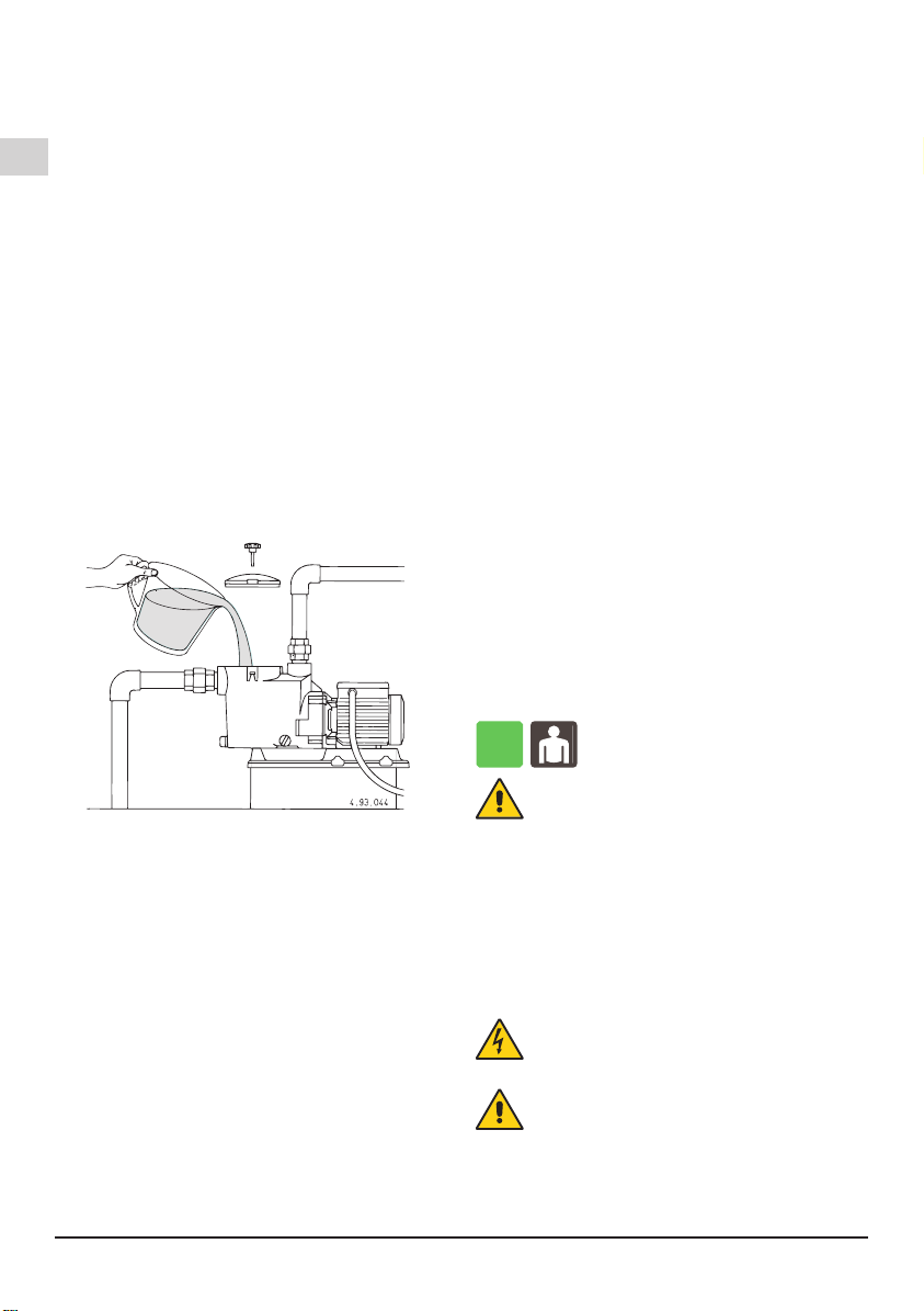
6.4.3. Suction pipe
The suction pipe must be perfectly airtight.
With a pump located below water level (inow under
positive suction head) (section 13., g. 7), install inlet
and outlet valves to isolate the pump.
With a pump located permanently above the water
level (suction lift operation), with various suction pipes
(for skimmers, main drain, tting for vacuum cleaner),
connect all the pipes with their own gate valve to a
manifold. As far as possible, locate the pipes and
the manifold below water level with the pump being
reached by a single vertical pipe (see section 14.,
gure 8b and section 7.2.3.).
With a pump located permanently above the water
level of a swimming pool, avoid suction lifts higher
than 3 m with respect to the main drain. With a suction
lift above 1,5 m t a check valve (accessible) in the
suction line from the main drain.
In operating with exible hoses, use a reinforced spiral
suction hose in order to avoid hose narrowing due to
suction vacuum.
6.4.4. Delivery pipe
Fit a gate valve in the delivery pipe to adjust delivery
and head.
Install a pressure gauge.
6.5. Electrical connection
OFF
Electrical connection must be carried out only
by a qualied electrician in accordance with
local regulations.
Follow all safety standards.
The unit must be properly earthed (grounded).
Connect the earthing (grounding) conductor to the
terminal with the marking.
Compare the frequency and mains voltage with
the
name-plate data and connect the supply conductors
to the terminals in accordance with the appropriate
diagram inside the terminal box cover.
ATTENTION: never allow washers or other
metal parts to fall into the internal cable
opening between the terminal box and
stator. If this occurs, dismantle the motor to
recover the object which has fallen inside.
If the terminal box is provided with an inlet gland, use
a exible power supply cord of the H07 RN-Ftype with
section of cable not less than (par. 16 TAB 1).
If the terminal box is provided with an inlet bushing,
connect the power supply cord through a conduit.
For use in swimming pools, garden ponds and similar
places, a residual current device with IΔN not
exceeding 30 mA must be installed in the supply circuit.
Install a device for disconnection from the mains
(switch) with a contact separation of at least 3 mm in
all poles.
With a three-phase motor install an overload protection
device appropriate for the rated current of the pump.
Single-phase MPCM, are supplied with a capacitor
connected to the terminals and (for 220-240 V - 50 Hz)
with an incorporated thermal protector.
In Austria pumps to be used in swimming pools and
garden ponds should be equipped with a xed con-
nection line according to ÖVE B/ EN 60555 Part 1 to
3; power supply should be via a ÖVEtested isolating
transformer whereby the secondary nominal voltage
should not exceed 230V.
ATTENTION: When the pump is fed by a
frequency converter, the minimum frequency
should not fall below 25Hz and in any case the
total head of the pump should never be lower
than 3 m.
7. STARTUP AND OPERATION
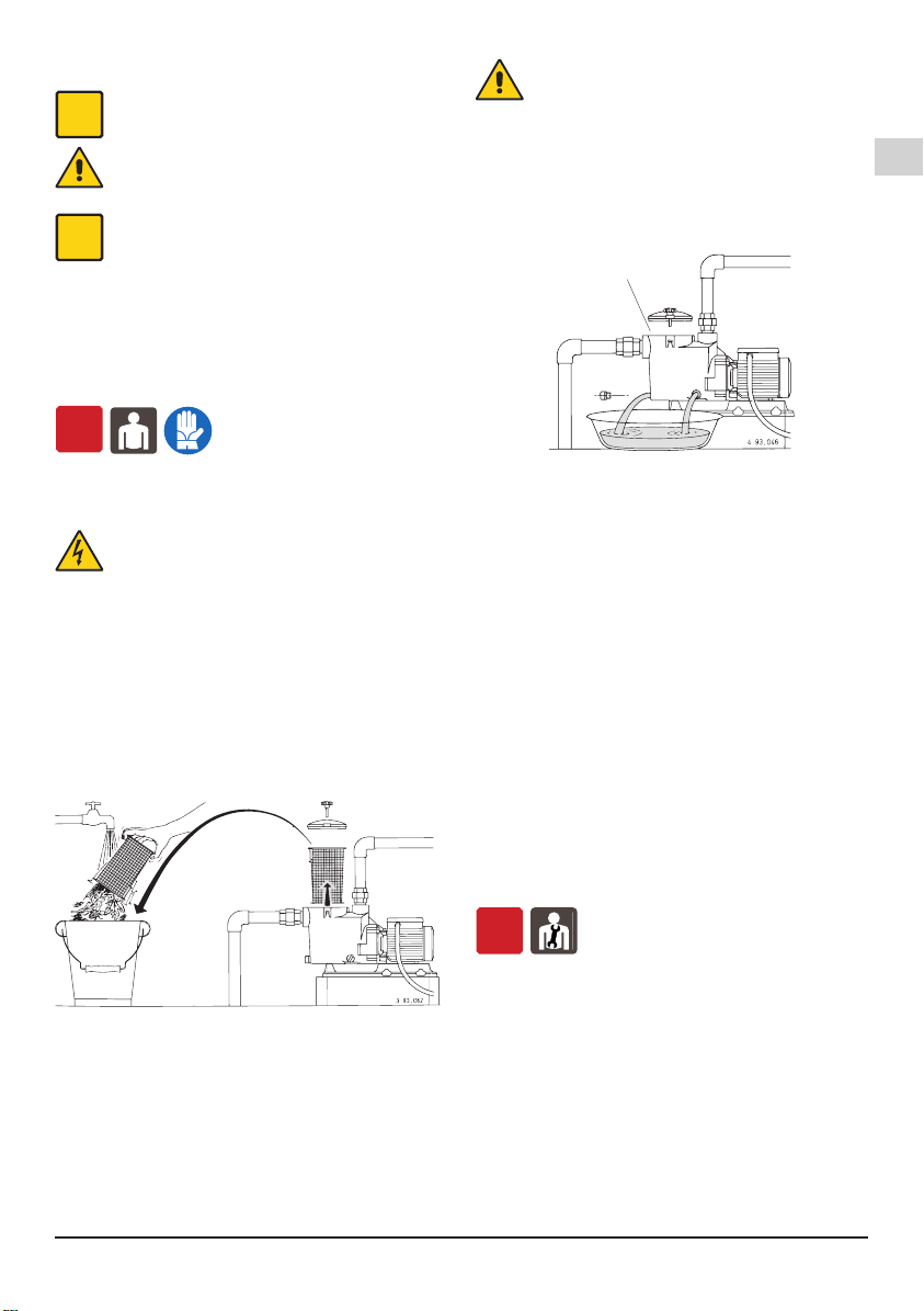
7.1. Preliminary checks before start-up of the
pump
Do not start-up the device in case of damaged parts.
7.2. First starting
OFF
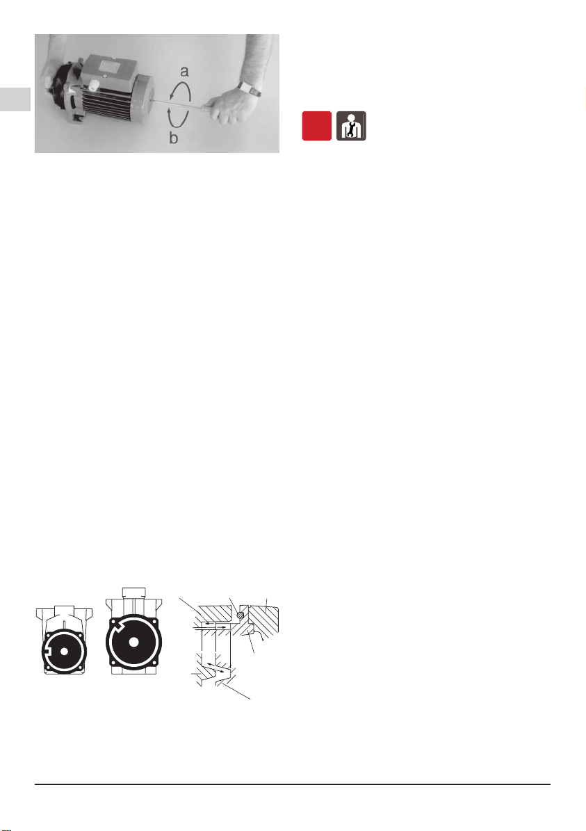
7.2.1. Checking the direction of rotation
ATTENTION: when the pump is started for the rst
time, with three-phase motors check the direction
of rotation.
With the three-phase models MPC 51, 61, 71, check
the direction of rotation before lling the pump (see
also section 8.4.).
MPC Rev17.indd 13 29/08/17 11:59

GB
Page 14 / 80 MPC Rev17 - Operating Instructions
First check that the shaft turns by hand.
For this purpose use the screwdriver notch on the shaft
end at the motor fan side. Turn the shaft by hand only
in the direction indicated by the arrows on the pump
casing.
Do not start the motor if the shaft is jammed.
If jammed, the impeller may unscrew should the
motor start rotating backwards. Reverse rotation
can also damage the mechanical seal.
Momentarily start the motor to check rotation of the
pump shaft, which must be as shown by the arrows
on the pump casing: clockwise when viewing the shaft
from the motor end. Otherwise, disconnect electrical
power and reverse the connections of two phases.
7.2.2. Filling
ATTENTION: avoid running dry.
When operating with the pump below water level
(inow under positive suction head), ll the pump by
opening the suction gate valve slowly and completely,
keeping the delivery gate valve open to release the air.
When the pump is located above the water level
(suction lift operation) ll the pump with water up to
suction port level through the opening on the strainer
after removing the cover (g. 2).
Fig. 2 Filling
After starting, check that the pump works within its eld
of performance and that the absorbed current shown
on the name-plate is not exceeded; otherwise adjust
the delivery gate valve.
Avoid long operation with a closed valve.
7.2.3. Self-priming
(Capability to clear the air in the suction pipe when
starting with the pump located above the water level
and when the suction pipe cannot be lled manually, as
in the case of a missing foot valve).
Maximum suction lifts and minimum self-priming times
(see the data sheet) are reached with a standard
electric motor (n = 2900 rpm), air-free water with a
temperature below 25 °C and a single suction pipe with
inlet diameter equal to that of the suction connection
of the pump.
Conditions for self-priming:
• Pump casing lled with water up to suction port level
before starting.
Note that with suction lift above 1,5-2 m (without a
foot valve or a check valve into the suction pipe)
the lling operation must be repeated before each
start-up.
• Suction and discharge valves completely opened and
pipes not obstructed.
• Strainer basket not obstructed.
• Suction pipe with connections perfectly airtight, and
properly immersed in the water to be lifted.
• O-ring on the strainer casing and mechanical seal
perfectly airtight (properly seated, clean and not
damaged).
• Hand wheels on strainer cover and thumbscrew
drain plug on strainer casing tightened to prevent air
entering.
• Discharge pipe without check valve, with minimum 80
cm straight vertical free pipe above discharge port.
With suction lift below 2 m vertical section on the
pump can be 50 cm. With suction lift lower than 1 m,
an elbow can be mounted directly onto the delivery
port without a vertical section of piping.
On expiry of the foreseen times, make sure (through
the transparent strainer cover) pump priming has
taken place and that water is owing regularly.
If the pump does not prime, check all conditions
above and remedy where necessary.
Repeat the priming operation again after the pump has
been completely lled with cold water.
Avoid long operation with an unprimed pump or
with a suction pipe not immersed in the water i.e. if
water level of the pool falls too low.
By lowering the water to a level below the skimmers
and other suction ports (for emptying of the pool), keep
open only the gate valve in the pipe for suction from
the bottom (main drain).
7.3. Switch off of the pump
ON
The appliance must be switch off every time
there are faults. (see troubleshooting).
The product is designed for a continuous duty, the
switch off is performed by disconnecting the power
supply by means the expected disconnecting devices.
(see paragraph “6.5 Electrical connection”).
8. MAINTENANCE
Before any operations it's necessary to disconnect the
power supply.
If required ask to an electrician or to an expert
technician.
Every maintenance operations, cleaning or
reparation executed with the electrical system
under voltage, it could cause serious injuries
to people.
If the supply cord is damaged, it must be
replaced by the manufacturer, its service agent
or similarly qualied persons in order to avoid
a hazard.
In case of extraordinary maintenance, or maintenance
operations that require part-removing, the operator
must be a qualied technician able to read schemes
and drawings.
MPC Rev17.indd 14 29/08/17 11:59

GB
MPC Rev17 - Operating Instructions Page 15 / 80
It is suggest to register all maintenance operation
executed.
i
During maintenance keep particular attention in
order to avoid the introduction of small external
parts, that could compromise the device safety.
It is forbidden to execute any operations with
the direct use of hands. Use water-resistant,
anti-cut gloves to disassemble and clean the
lter or in other particular cases.
i
During maintenance operations external
personnel is not allowed.
Maintenance operations that are not described in
this manual must be made only by special personnel
authorized by Calpeda S.p.A.
For further technical information regarding the use or
the maintenance of the device, contact Calpeda S.p.A.
8.1. Routine maintenance
OFF
The motors with supply current directly switched
by thermally sensitive switches can start
automatically.
Disconnect electrical power before any
servicing operation and make sure the
pump cannot be accidentally switched on.
Inspect and clean the strainer basket periodically.
The frequency of cleaning depends on operation time
of the pump, pool environment, wind (for open air
swimming pools) and the number and behaviour of the
bathers.
With the pump located below water level, close the
suction and delivery gate valves before removing the
cover.
The strainer can be easily accessed by removing the
strainer cover (g. 3).
Fig. 3 Removing and cleaning the strainer
ATTENTION: do not use oil to lubricate the O-ring
seal. Use only water and neutral soap to clean the
transparent strainer cover. Do not use solvents.
After cleaning, put the strainer basket in its proper
position. Fill with water up to suction port level (see
section 7.2.2.).
Position the strainer cover properly with the O-ring seal
on the casing and tighten the handwheels uniformly.
Disinfectant or chemical products for water
treatment must not be poured directly into
the pump.
Risk of reactions and emission of harmful fumes. Risk
of corrosion in stagnant water conditions (also with an
increase in temperature and decrease of pH value).
If the event of prolonged standstill periods or
if freezing may be expected, drain the pump
completely by removing the two thumbscrew drain
plugs with reusable O-ring gaskets (g. 4).
Fig. 4 Draining
Tighten drain plugs by hand. Do not use pliers or
other tools.
If necessary, use pliers only to unscrew. Excessive
torque may cause damage.
ATTENTION: after a long idle period, before
restarting the unit, ll the pump casing with water
and check with a screwdriver that the shaft is not
jammed.
If the shaft is jammed, dismantle the motor and remove
the cause.
8.2. Dismantling the system
Close the suction and delivery gate valves and drain
the pump casing before dismantling the pump.
8.3. Dismantling the pump
OFF
Drain the pump casing before dismantling (see g.
4 and section 12.). For dismantling and reassembly
see construction in the cross-section drawing (section
15.).
Remove the motor assembly with the lantern bracket
(32.00) from the pump casing (14.00), after removing
the screws (14.24), the nuts (14.28) and the washers
(14.29), levering them out with two screwdrivers in
diametrically opposed positions.
To remove the impeller (28.00) insert a large straight-
blade screwdriver in the slot on the shaft (78.00) at the
ventilation end.
Grip the impeller with one hand and unscrew it, turning
the shaft counter-clockwise and twisting with both
hands (g. 5a).
Air inlet
MPC Rev17.indd 15 29/08/17 11:59

GB
Page 16 / 80 MPC Rev17 - Operating Instructions
Fig. 5 Dismantling (a) and remounting (b) the impeller
If it is not possible to hold or move the shaft with the
screwdriver, remove the fan cover (90.00) and motor
fan (88.00) and unscrew the impeller by gripping the
shaft with a suitable wrench.
With the impeller the rotating part of the mechanical
seal (36.00) will be removed.
8.4. Assembling
To replace to mechanical seal (36.00) place the
rotating part of the seal on the impeller hub (28.00) and
push the spring right down as far as the front shoulder.
In this way, correct spring compression will be ensured
in subsequent assembly.
Lubricate the seal with water and align the impeller on
the motor shaft.
ATTENTION: with the three-phase models, to avoid
the unscrewing (and breaking) of the impeller
should the motor start rotating backwards, clean
the threaded shaft end and apply on the rst half of the
threaded part Loctite 243.
If this type of product is not used, check the direction
of rotation before lling the pump (to avoid unscrewing
due to the resistant-force of the water in the case of a
backward rotation).
Grip the impeller with one hand and turn the shaft with
a screwdriver in the clockwise direction until tight.
With this operation the front surfaces of the mechanical
seal come into contact without rubbing against each
other during tightening (g. 5b). Clean the O-ring
(14.20) and seal surfaces with water.
When replacing the motor assembly with the
impeller be careful to insert the locating lug inside
the pump casing (14.00) into the locating slot on
the diffuser cover (27.00) (g. 6).
4.93.149
MPC
11
, 21, 31, 41
MPC
51, 61, 71
14.00 14.20 32.00
27.00
14.00
27.00
Fig. 6 Locating lug/slot for assembling pump casing
(14.00) - diffuser cover (27.00).
ATTENTION: to avoid leakage or failure due to
misalignment and localized overstressing, the screws
(14.24) with the nuts (14.28) must be uniformly
tightened with alternated crossover tightening in
diametrically opposed positions. Tightening torque for
screws (14.24): 7 Nm.
9. DISPOSAL
OFF
The nal disposal of the device must be done by
specialized company.
Make sure the specialized company follows the
classication of the material parts for the separation.
Observe the local regulations and dispose the device
accordingly with the international rules for environment
protection.
10. SPARE PARTS
10.1. Spare-parts request
When ordering spare parts, please quote their
designation, position number in the cross section
drawing and rated data from the pump name plate
(type, date and serial number).
The spare parts request shall be sent to CALPEDA
S.p.A. by phone, fax, e-mail.
11. ESIGNATION OF PARTS
Nr. Designation
14.00 Pump casing
14.14 Plug
14.15 O-ring
14.20 O-ring
14.24 Screw
14.28 Nut
14.29 Washer
15.00 Strainer cover
15.04 O-ring
15.12 Hand wheel
15.16 Square nut
15.50 Strainer basket
27.00 Diffuser cover
27.04 Diffuser funnel
27.08 O-ring
28.00 Impeller
28.12 Retaining ring
36.00 Mechanical seal
70.00 Lantern bracket
73.00 Ball bearing
73.08 V-ring, pump side
76.00 Motor casing with winding
76.16 Support
78.00 Shaft with rotor packet
81.00 Ball bearing
82.00 Motor end shield
82.04 Compensating spring
82.08 Screw
88.00 Motor fan
90.00 Fan cover
90.04 Screw
92.00 Tie-bolt
98.00 Terminal box cover
Changes reserved.
MPC Rev17.indd 16 29/08/17 11:59

GB
MPC Rev17 - Operating Instructions Page 17 / 80
12. TROUBLESHOOTING
OFF
WARNING: Turn off the power supply before performing any operations.
Do not allow the pump or motor to run when dry even for a short period.
Strictly follow the user instructions and if necessary contact an authorised service centre.
PROBLEM
PROBABLE CAUSES POSSIBLE REMEDIES
1)
The motor does
not start
1a) Unsuitable power supply
1b) Incorrect electrical connections
1c) Engine overload protective device cuts
in.
1d) Blown or defective fuses
1e) Shaft blocked
1f) If the above causes have already
been checked, the engine may be
malfunctioning
1a) Check that the mains frequency and voltage correspond to the
electrical characteristics shown on the indicator plate
1b) Connect the power supply cable to the terminal board correctly. Check
that the thermal overload protection is set correctly (see data on the
engine indicator plate) and make sure that the fuseboard upline of the
engine has been properly connected
1c) Check the power supply and make sure that the pump shaft is turning
freely. Check that the thermal overload protection has been set
correctly (see engine indicator plate)
1d)
Replace the fuses, check the electric power supply and points a) and c)
1e) Remove the cause of blockage as indicated in the “Blocked pump”
instruction booklet
1f) Repair or replace the engine by applying to an authorised service
centre
2)
Pump blocked 2a) Prolonged periods of inactivity with
formation of rust inside the pump
2b) Presence of solid bodies in the pump
rotor
2c) Bearings siezed
2a) Rotation may be started directly from the pump shaft or from the
joint (remember to turn off the electricity supply rst ) or contact an
authorised service centre
2b) If possible, dismantle the pump casing and remove any solid foreign
bodies inside the rotor, if necessary contact an authorised service
centre
2c) If the bearings are damaged replace them or if necessary contact an
authorised service centre
3)
The pump
functions
but no water
comes out
3a) Possible inltration of air from suction
tube connections, drain plugs or lling
of pump or from the gaskets of the
suction pipe
3b) Foot valve blocked or suction pipe not
fully immersed in liquid
3c) Suction lter blocked
3a) Check which part is not tight and seal the connection adequately
3b) Clean or replace the bottom valve and use a suction pipe suitable for
the application
3c) Clean the lter, if necessary, replace it . See point 2a) also.
4)
Insufcient ow 4a) Pipes and accessories with diameter
too small causing excessive loss of
head
4b) Presence of deposits or solid bodies in
the internal passages of the rotor
4c) Rotor deteriorated
4d) Worn rotor and pump case
4e) Excessive viscosity of the liquid
pumped (if other than water)
4f) Incorrect direction of rotation
4g) Suction head excessive in relation to
the suction capacity of pump
4h) Suction pipe too long
4a) Use pipes and accessories suitable for the specic application
4b) Clean the rotor and install a suction lter to prevent other foreign
bodies from entering
4c) Replace the rotor, if necessary, contact an authorised service centre
4d) Replace the rotor and the pump casing
4e) The pump is unsuitable
4f) Invert the electrical connections on the terminal board or control panel
4g) Try to close the feeder gate partially and/or reduce the difference in
level of the pump and the liquid being aspirated
4h) Bring the pump closer to the suction tank so as to use a shorter pipe.
If necessary use a pipe of a wider diameter
5)
Noise and
vibrations
from the pump
5a) Rotating part unbalanced
5b) Worn bearings
5c) Pump and pipes not rmly attached
5d) Flow too strong for the diameter of the
delivery pipe
5e) Functioning in cavitation
5f) Unbalanced power supply
5g) Incorrect alignment of pump-motor unit
5a) Check that no solid bodies are obstructing the rotor
5b) Replace the bearings
5c) Anchor the delivery and suction piping as needed
5d) Use bigger diameters or reduce the pump ow
5e) Reduce the ow by adjusting the feeder gate and/or using pipes with
a bigger internal diameter. See point 4g) too
5f) Check that the mains voltage is right
5g) If necessary, the unit must be re-aligned
6)
Leakage from
the mechanical
seal
6a) The mechanical seal has functioned
when dry or has stuck
6b) Mechanical seal scored by presence
of abrasive parts in the liquid pumped
6c) Mechanical seal unsuitable for the
type of application
6d) Slight initial drip during lling or on rst
start-up
In cases 6a), 6b) and 6c), replace the seal, if necessary contact an
authorised service centre
6a) Make sure that the pump casing (and the suction pipe if the pump is
not self-priming) are full of liquid and that all the air has been expelled.
See point 5 e) too.
6b) Install a suction lter and use a seal suited to the characteristics of the
liquid being pumped.
6c) Choose a seal with characteristics suitable for the specic application
6d)
Wait for the seal to adjust to the rotation of the shaft. If the problem
persists, see points 6a), 6b) or 6c) or contact an authorised service centre.
MPC Rev17.indd 17 29/08/17 11:59

中文
页码 66 / 80 MPC Rev17 - 安装使用手册
本操作手册属CALPEDA S.P.A.所有,禁止任何形式的
复制,即使是部分的。
1. 总则
使用本产品前请仔细阅读此操作手册的内容,并保留
此操作手册以供参考。
此操作手册为意大利语,如有翻译偏差以意大利语为
准。
此操作手册是安全保障必不可少的一部分,在产品最
终达到正常工作前请牢记本手册。
万一用户不慎遗失本手册,可以向CALPEDA S.P.A.或
其代理商要求一份复印件,请详述产品铭牌上的资料
(见2.3标记)
未经制造商认可的有关其产品或部件的任何更改变
化,将撤消“CE声明”和质保。
此产品不应让8岁以下的未成年、
身体有缺陷、心智不全或无任何
经验的人操作,除非在充分的指
导或监督下让相关人员知道如何
安全的使用,并且通过一个负责
人来让相关人员了解到可能会产
生的危险。
不得让儿童接触本产品。
用户有义务清洁和维护本产品。
除非在有人监督的情况下,否则
儿童不应清洁和维护本产品。
仔细阅读安装部分的规定:
-最大允许的结构工作压力详见3.1
-电源线的类型及剖面详见6.5
-
所安装电器设备的防护类型详见6.5
1.1. 符号标记
为了便于理解本操作手册,下面给出常用标记符号的
含义。
一定要注意通告和警告的标记,否则可能导致
产品损坏或人身安全的风险。
忽略有关电气的警告,可能导致产品损坏或人
身安全的风险
i
提示和警告正确操作处理产品及其部件
最终用户可以进行的操作
终端用户:仔细阅读本操作手册后,产品使用
者可以负责正常状态下的维护工作。他们可以
进行产品的清洁和长期停滞后的重新启动此类
标准维护工作。
必须由有资格的专业电工才能进行的操作
专业电工:有资格的专业电工,负责所有电气
设备的运行包括维护,应具有高压电资格。
必须由有专业技术资格的人才能进行的操作
专业技术人员:正常状态下,具有产品安装和
维护能力的专业技术人员,可以从事电气和机
械方面的维护工作。能够从事简单的与设备维
护相关的电气和机械方面的操作。
指示必须使用个别的保护装置
OFF
必须关断电源并断开与电源的连接才能进行的
操作
ON
必须接通电源才能进行的操作
1.2. 制造商名称和地址
制造商名称:CALPEDAS.P.A.
地址:ViaRoggiadiMezzo,39
36050MontorsoVicentino-Vicenza/Italia
www.calpeda.it
1.3. 授权操作者
本产品只能由有经验的终端用户和专业技术人员操作
i
禁止终端用户操作那些只能由专业技术人员操
作的工作,对未按本规章执行而引起的损害制
造商不负任何责任
1.4. 质保
质保参见总则和销售条款
i
质保期内将更换或维修有问题的产品部件(由
制造商验证的)。
下面因素不在质保范围:
-由于产品使用者没有按照说明及本手册的通告信息操
作造成的损坏
-未经制造商认可的对产品的任何改变而造成的损坏
-由非专业人员操作造成的损坏
-由不当的维修造成的损坏
摘要
1. 总则................................................................. 66
2. 技术说明......................................................... 67
3. 技术特性......................................................... 67
4. 安全性............................................................. 67
5. 搬运操作......................................................... 67
6. 安装................................................................. 68
7. 启动和运行...................................................... 69
8. 维修................................................................. 70
9. 处理................................................................. 71
10. 备件................................................................. 71
11. 部件名称......................................................... 71
12. 常见故障和解决方法....................................... 72
13 安装示意图.................................................... 73
14 安装示意图.................................................... 75
15 组装与分解图.................................................. 77
声明....................................................................... 79
MPC Rev17.indd 66 29/08/17 12:00

中文
MPC Rev17 - 安装使用手册 页码 67 / 80
1.5. 技术支持
任何技术支持、备件及更多的产品信息均可联
系:CalpedaS.p.A.(附件1.2章).
2. 技术说明
自吸式泳池泵内含过滤器。
泵头使用优质塑胶制成,具有极强的耐腐蚀及耐磨损
性能。
不锈钢材质的扩散器。
一体式底座。
2.1. 预期用途
用于清洁或含有微量固体颗粒悬浮物的水,最高使用
温度为60°C
2.2. 不当使用
本产品只用于2.1中所述用途
除了本说明手册中指示的用途外,严禁其他不当
用途
不当使用将降低本产品的安全性和效率,由于不当使用
而造成的损坏和意外,CALPEDA不承担责任
2.3. 标记
下面给出的是泵外壳上的标牌的图片
1型号
2流量
3扬程
4额定功率
5电源电压
6电流
7注释
8频率
9运行工作制
10绝缘.等级
11重量
12功率因数
13转速rpm
14保护等级
15序列号
16认证
泵标牌图示
Made in Italy
MONTORSO
XXXXXXX
Q min/max X/X m3/h
XXXXXXX
H max/min X/X m IP XX
n XXXX/min
220∆/380Y V3~50Hz cosø X
X/X A
XXXXXXXX
S1 l.cl. X X kg
X kW (XHp) S.F.
VICENZA
1
2
3
4
5
6
7
8910
16
15
14
13
12
11
3. 技术特性
3.1. 技术参数
尺寸和重量(详见产品样本)
额定转速2900/3450rpm
保护等级IPX4
电压/频率
-高达240V1~50/60Hz
-高达480V3~50/60Hz
检查主电源的电压、频率等参数是否符合电机铭牌所示
标牌的电气数据依据电机的正常功率而标出。
噪声等级<70dB(A). MPC7: 72 dB (A).
每小时最大启动次数:时间间隔相同的情况下可启动
10次
泵壳允许最大压力:25m(2,5bar).
4. 安全性
4.1. 总则
使用本产品前应了解有关安全的指示
仔细阅读所有的操作说明和从搬运到处理的每
一步指示专业技术人员必须认真遵从所有的适
用标准和法律,包括产品应用地当地的规章
产品安装使用应符合现行的安全法规
不当的使用可能会对人身、动物和其他对象造成损害
制造商对由于不当使用或未按本操作手册和标牌的标
示使用所造成的损坏不负责任
i
按照日程维护计划表操作并及时更换损坏的部
件可使产品工作在最佳状态
使用CALPEDA S.P.A或其指定代理商提供的原
厂配件
不要撕下或改变产品上的标识
当产品有问题或部件有损坏的情况下不要启动
产品
由于维修时会全部或部分的拆开产品,因此之前
务必断开供电电源
4.2. 安全装置
本产品具有全外部壳体,可防止与内部部件的任何接触
4.3. 剩余风险
当按照本产品的设计功能和所有安全规则使用本产品
时没有剩余风险
4.4. 通告和安全预示
没有任何安全预示在此类产品上面
4.5. 个别的保护装置
在安装、使用和维修期间,建议操作人员使用适合此
操作的个别保护装置或手段当进行日常或个别的维修
工作时
标示的个别保护装置
手的保护
(防热、化学品和机械损害的手套)
5. 搬运操作
货物应包装完好
运输过程中应避免超重,并确保货物不会移动。确保
运输车辆和所运货物尺寸相符合
无需特殊车辆运输
运输车辆应与被运货物的尺寸重量相符合(尺寸和重量
详见产品样本).
MPC Rev17.indd 67 29/08/17 12:00

中文
页码 68 / 80 MPC Rev17 - 安装使用手册
5.1. 搬运
小心搬运,轻拿轻放
避免冲撞包装材料以免损坏泵的外套
对于重量超过25公斤的包装物需由两人同时搬抬
6. 安装
6.1. 尺寸
设备的外形尺寸(详见产品样本)
6.2. 环境要求和安装位置的尺寸
客户应将本产品妥当的安装于适当位置以满足设备的
要求(供电需要等)
安装位置应满足章节3.2中的要求
禁止将产品安装于有潜在易燃易爆危险的环境中
6.3. 拆箱
i
开箱检查产品是否因运输而损坏
拆开的包装材料应根据产品使用国当地的法律规定遗
弃或再利用
6.4. 安装
MPC泳池泵必须安装在通风良好的环境中,其底脚向
下且转子轴应水平放置。
泵的安装位置应尽可能置于泳池附近。
为降低触电的风险,应将水泵安装于距泳池内
壁至少3米远的位置。当将水泵置于室外用于
便携式水泵时应提供适当的保护,保证泵基础
高度至少达到100mm来作为绝缘的基础。详见
6.5
为保证设备转子旋转自如,电机组应预留足够的空间
便于通风换气、设备检修、滤网的更换、灌泵以及排
水检查(包括螺丝刀的空间),参见图1。对于三相
的电机设备,还需要一定的空间检查电机转向是否正
确。
图1最小检修尺寸
6.4.1. 管路
为保证介质的流动性,管路的外径规格应按照,入口
流速不大于1.5m/s,出口流速不大于3m/s来提供。
注意:在连接管路前应确保管路的干净畅通。
一定浓度的砂砾,若其直径大于叶轮与耐磨环的径向
间隙(约1mm),会引起更快的磨损且泵效率会降低
10%左右。
管路的静压测试应大于2.5bar并且在实验时应将泵系
统以外的部分隔离。
(测试前后都应关闭泵的进出口阀门)
6.4.2. 管路的连接
应使用塑料材质的管路或接头配件。
对于连接到泵壳的螺纹接口处,应使用管路专用的密
封胶(如:乐泰5331)
不推荐使用聚四氟乙烯胶带。不允许使用纤维密封。
注意:请勿将螺纹管路或连接件拧得过紧。
管路或连接件只需要保证密封性即可。
过大的扭力会引起泵的损坏。
对于金属管路,应先通过一个带螺纹接头的塑料转换
单元连接至泵壳。
确保所有的管路的连接和支撑稳固并不会因此对泵产
生应力、扭力、或震动。决不能让水泵承受管路的重
量或热膨胀的影响。
管路的扭力或弯曲力会引起泵壳的损坏及漏水。
6.4.3. 入口管路
务必保证入口管路的气密性。
当泵安装在水位以下的位置时(保证入口的正水头)
(参见13章节,图7),安装入口和出口的阀门来隔离
泵和管路。
当泵安装在水位以上的位置时(自吸运行)用多
条入口管路(管路组成:撇清器,主排水管,真
空接头),将所有管路配件及配套闸阀连接至歧
管,确保管路和歧管在液位以下再通过一根垂直的
管路连接至泵(参见13章节,图8b及7.2.3章节)
当泵安装在水位之上时,入口主管路与泵的高度差不
能超过3m。建议在入口主管路之上1.5m高的位置安装
止回阀。若使用软管,请务必使用增强螺旋软管,防
止因真空吸力而导致进水不畅。
6.4.4. 出水管
在出水管道中安装一闸阀,以调节流量,扬程和 轴功
率.
一定要安装_压力表.
移除滤网 拆解电机
检查轴的
旋转
电机通风
排污
灌充
MPC Rev17.indd 68 29/08/17 12:00

中文
MPC Rev17 - 安装使用手册 页码 69 / 80
6.5. 电气联接
OFF
必须由合格电工根据当地规范进行电气联接.
必须遵守安全标准.
泵-电机机组必须可靠地接地.
把接地导线接到标有记号的端子上 .
请对照电源电压和铭牌上所标数值,根据接线盒内盖
上的电路图联接电源.
注意:绝对不允许将垫片等金属部件掉入电机接
线盒的定子线圈中.
如果发生此种问题,必须拆开电机,取出部
件。
如果接线盒的进线口为密封管,则应使用H07RN-F型柔
软的电线电缆的剖面不低于表(章16)的相关规定。
如果接线盒的进线口是套管,则应通过套管连接电
线。
作为用于游泳池,花园池塘的泵,必须在电源线路中
安装漏电保护器,其灵敏度不大于30毫安.
安装一个使电源断开的装置,各电极之间至少有3mm
的间隙.
对于三相电机,根据其额定电流一定要安装一个过载
保护装置曲线D.
对于单相的MPCM,泵,提供一个连接在接线柱上的电
容,对于220-240V-50Hz的电源,还提供一个相连的热
保护装置.
在奥地利必须通过。VE (奥地利电工协会)检验的隔离
变压器对在游泳池和花园池中使用的泵进行供电。按
照。VE B/EN 60555 第1 至3 部分标准的该泵装配有
一个固定的连接导线,同时二次额定电压不允许超过
230V。
注意:当泵由变频器控制的时候,频率不允许低
于25Hz并且水泵总扬程在任何情况下都不能低
于3m
7. 启动和运行
7.1. 启动前的预检
当存在有故障的部件时不要启动本产品
7.2. 首次启动
OFF
7.2.1. 检查转向
注意:对于三相电机,首次启动泵时要检查泵的转
向。
对于MPC51,61,71型号的泵在检查转向前应先灌泵(
详见8.4章节)
首次检查时,用手转动泵轴盘泵。
可以使用螺丝刀转动电机非驱动端的轴端后部。盘泵
时注意泵壳上指示的旋转方向。
如果泵轴有卡阻,不能启动电机。
有卡阻时,应卸下叶轮并启动电机让其反转。反向旋
转可能会损伤机封。
应让电机短时间反转的同时检查泵轴的转动情况。
7.2.2. 灌泵
注意:防止干转
当水泵在水位以下运行时(水会自行流进入口),通
过缓慢的开启闸阀使流入的水将空气排出。
当水泵在水位之上运行时(自吸运行),用清水通过
过滤器灌泵,直到水位与拆下的盖板水平。
图2灌泵
启动后,检查水泵现场的使用性能,同时其实际电流
不应超过名牌所示的电流要求,否则需要通过出口阀
门调节。
避免长时间闭阀运行。
7.2.3. 自吸
(当泵在水位上方运行且入口管路不能人工灌满水
时,应排空水泵入口管路内的空气,否则底阀将失
效)
最大自吸能力及自吸时间(见数据表)与电机相关
(n=2900rpm),不含空气的水温应低于25°C并且
泵入口与入口管路尺寸应相同。
自吸条件
•启动前将泵壳用水灌满至入口。
请注意,对于吸程要求高于1.5—2m的工况(入口管路
无底阀或止回阀),每次启动前必须灌泵。
•进出口阀门全开且管路畅通
•过滤器无阻塞
•入口管路必须完全密封,并且完全浸没在水中。
•在过滤器壳体、机封上的O型圈密封性能良好(安装
到位,清洁且无损)
•将在过滤器盖上的手轮和在过滤器壳体上的排污螺塞
拧紧,防止进入空气
•出口管路如果没有单向阀,用最短为80cm长度的垂
直自由管路连接至出口。吸程低于2m的垂直管路可
用50cm的管路。吸程低于1m时,则出口无需垂直
管路,可直接配合弯头使用。
定期检查,(通过透明过滤器盖)确保泵启动后内部
的水是流动的。
如果泵工作状态不佳,检查上述的条件要求并及时纠
正。
MPC Rev17.indd 69 29/08/17 12:00

中文
页码 70 / 80 MPC Rev17 - 安装使用手册
再次启动运行水泵时,应完全充满冷水。
避免一台状态不佳的泵或入口管路未完全浸入水中(
水池中的水位过低)的泵长时间运行。
当水位下降到低于撇清器以及其他入口(排空水池)
,保持水池底部管路上的闸阀打开(主排水)。
7.3. 泵的停车
ON
当存在故障时必须关闭设备
本产品设计为连续工作, 当希望断开本产品时可断开供
电电源停机(见章节6.5电气连接)
8. 维修
任何维修操作前都应该先断开电源,必要时可由电工或
专业技术人员操作
在带电情况下的任何类似清洁或维修的操作都
可能对人身造成严重伤害
如果电源电缆出现损坏,必须由厂商、厂商代
理或相同资质的人员进行更换。
突发的维修或需要部分拆解零件的维修,都必须由能看
懂结构图的专业人员来操作
i
建议记录所有的维修过程,在维修期间特别小心
注意不要带入任何外部细小异物,这会对产品的
造成损害
不要在无防护措施的情况下用手直接操作,应
带防水防割的手套进行过滤器的拆解清洁或其
他维修工作
i
维修期间无关人员禁止入内
本操作手册中没有介绍的维修工作只能由CALPEDA授
权的特别人员来完成
有关产品使用和维修的更多信息请联系CALPEDA
S.P.A.
8.1. 日常维护
OFF
电机通过热敏开关直接控制电流的通断,可自动启
动。
任何检修都需要断开电源并且确保不会意外开
启。
定期检查并清理过滤器。清洗的频率取决于泵的运行
时间、水池环境、风(户外泳池)以及游泳人的数
量。
对于安装在水位下的泵,移去盖板前应关闭进出口闸
阀。
移开盖板后,过滤器可以很容易的取放(图3)。
图3移除和清理滤网
注意:不要给O型密封圈使用油来润滑。使用水和中性
肥皂清理透明滤网盖。不能使用有机溶剂。
清理后,回装滤网提篮到恰当的位置。
灌泵至入口处(见构造图7.2.2)。
正确的回装滤网盖,通过手轮保证壳体上的O型圈密
封。
用于水处理的消毒剂或化学品决不能直接倒入
泵中。
有化学反应的废气物扩散的风险。不流动的水有锈蚀
的风险(也会随着温度的升高PH值会下降)
如果长期停滞或有冻结的预期,则应通过移除两个螺
母塞及配套的O型圈垫片排空水泵(图4)。
图4排水
用手拧紧排水塞。不要使用钳子或工具。
如果必要,只能使用钳子松开螺丝。过大的扭力会造
成损坏。
注意:停滞一个较长周期后,重启前应灌泵并用螺丝
刀检查泵轴是否卡阻。
如果卡阻,应拆卸电机并排除故障。
8.2. 系统的分解
分解前,关闭进出口隔栅.
8.3. 泵的拆解
OFF
拆解前排空泵(见图4及剖面图12)。对于拆解和重新
装配见剖面构造图(剖面图15)
若从泵壳(14.00)上拆下带支架(32.00)的电机,
进气口
MPC Rev17.indd 70 29/08/17 12:00

中文
MPC Rev17 - 安装使用手册 页码 71 / 80
应卸下螺丝
(14.24)、螺母(14.28)及垫片(14.29
)
,再用螺丝刀在对向位置从泵壳上分离出电机。
用较大的一字螺丝刀插入电机轴(78.00)末端上的槽
口来拆卸叶轮(28.00)。
用手握住叶轮并拧开叶轮,双手配合相对反向拧动轴
拆卸叶轮(图5a)。
图5拆卸(a)和回装(b)叶轮
如果不能用螺丝刀稳定或移动轴,则拆下风扇盖
(90.00)和电机风扇(88.00)再用一个合适的扳手
固定住轴并拧开叶轮。
对于机械密封(36.00)在与叶轮同时转动的部分也应
拆下。
8.4. 组装
对于安装机封(36.00),应把机封的转动部分套在叶
轮的筒形部分中,并尽量把弹簧推压到轮肩部位,这
样在随后的组装中就能保证正确的弹簧压缩量,以减
少机械密封漏水机会。
用水润滑密封并且对齐电机轴上的叶轮来回装。
注意:对于三相模式,应将电机反向转动避免叶轮的
螺栓松动(或破损),清洁轴端上的螺纹并在螺纹前
半部分涂抹乐泰243.
如果此类型的产品还未开始使用,则应在灌泵前先检
查泵的转向(避免类似水锤的力量使叶轮反转而导致
的松动)
单手握住叶轮同时用螺丝刀顺时针转动轴直到拧紧。
用这种方法来使机械密封的各密封面有效密封,而不
致在紧固时引起相互摩擦(图5b)。用水来清洁O型
圈(14.20)和密封面。
在更换佩带叶轮的电机时,应小心的插入泵壳(14.00
)内的定位凸缘进入到扩散器盖(27.00)上的定位槽
(图6)。
4.93.149
MPC
11
, 21, 31, 41
MPC
51, 61, 71
14.00 14.20 32.00
27.00
14.00
27.00
图6用于组装泵壳(14.00)-扩散器盖(27.00)的定
位凸缘/槽
注意:为避免安装失误和局部的超应力导致的泄露或
失效,螺栓(14.24)及配套螺母(14.28)必须在对角位
置均匀的上紧。螺栓(14.24)上紧力矩为:7Nm。
9. 处理
OFF
产品的最终处理应由专业公司操作
确保专业公司是按照材料分类方式处理
按照当地的法规和有关环境保护的国际准则处理
10. 备件
10.1. 订购备件
订购备件时请根据剖面图提供备件的名称和位置编号
及泵铭牌上的数据(型号、参数和序列号)
备件需求请电话、传真、邮件给CALPEDAS.P.A
11. 部件名称
名称
14.00泵壳
14.14水堵
14.15O形圈
14.20O型圈
14.24螺丝
14.28螺母
14.29垫片
15.00过滤器盖
15.04O形圈
15.12手动旋钮
15.16方螺帽
15.50过滤器
27.00盖-扩散体
27.04扩散体-漏斗形
27.08O形圈
28.00叶轮
28.12弹性挡圈
36.00机械密封
70.00泵侧电机盖
73.00泵侧轴承
73.08V型环,泵侧
76.00带绕组的
76.16支脚
78.00轴与转子
81.00风扇侧轴
82.00风扇侧
82.04补偿弹
82.08螺丝
88.00电机风
90.00风扇罩
90.04螺丝
92.00连接螺栓
98.00接线盒
保留更改权利
MPC Rev17.indd 71 29/08/17 12:00

中文
页码 72 / 80 MPC Rev17 - 安装使用手册
12. 常见故障和解决方法
OFF
警告:任何操作之前均应断开电源.
决不允许泵组干转,即使是短时间的.
严格按照使用说明书操作,如有必要请联系授权服务中心.
故障现象 故障的可能原因 解决办法
1)
电机不启动
1a)电源供应不匹配
1b)接线错误
1c)电机过载保护装置动作
1d)保险丝故障
1e)轴卡死
1f)若上述原因已检查确认,那可
能是电机故障
1a)检查供电电源的电压、频率是否符合电机铭牌所示
1b)正确连接主电源线到接线端子,检查热过载保护装置的
设置是否正确(见电机铭牌上的数据)务必保证电机保
险丝安装正确。
1c)检查供电电源并确保泵轴可自如的转动。检查热过载保
护是否被正确的设定(看电机铭牌数据)
1d)更换保险丝,检查主电源重复a)和c)的步骤
1e)见2)泵卡阻
1f)向授权的服务中心申请维修或更换电机
2)
泵卡阻
2a) 设备长时间的停放使泵内部
生锈
2b)泵转子内部有固体异物
2c)轴承损坏
2a)从泵轴或联轴器处直接盘泵(盘泵前首先要切断电源)
,或者联系授权服务中心
2b)如果可能,请拆除泵壳并除去内部转子中的异物。如有
需要请联系授权服务中心
2c)如果轴承受损请更换或联系授权服务中心
3)
泵工作但不
出水
3a)
可能入口管路连接处漏气、或是
排/灌水堵处、入口管路垫片处)
3b)底阀堵塞或吸入管没有完全浸
入在液体中
3c)入口过滤器堵塞
3a)检查看哪里没拧紧连接到位并正确连接
3b)清洁或更换底阀并使用适合于工况的进口管路
3c)清洁过滤器,或更换。同时参见2a)
4)
流量不足
4a) 管路及其附件直径过小导致水
头损失过大
4b)流道内有沉积物或固体异物
4c)转子腐蚀损坏
4d)转子和泵壳磨损
4e) 泵送介质粘度过高(不同于
水)
4f)旋转方向错误
4g)吸程超过了泵的自吸能力
4h)入口管路过长
4a)请使用符合工况的管路及其附件
4b)清洁转子并安装入口过滤器以防止外部固体异物进入
4c)更换转子,如果需要请联系授权服务中心
4d)更换转子和泵壳
4e)泵不适用
4f)在控制柜内或电机接线盒内对调任意两根接线
4g) 请尝试部分关闭供水阀门和/或降低泵的安装高度,液
体将被吸入。
4h) 使泵尽量靠近入口水箱以便缩短进口管路。如有必要应
选用大口径进水管。
5)
泵的噪音和
震动
5a)转子不平衡
5b)轴承磨损
5c)泵和管路未固定到位
5d)输送管路直径过小
5e)发生汽蚀
5f)供电电源不平衡
5g)泵与电机不同心
5a)检查转子中是否有固体异物
5b)更换轴承
5c)将进出水管路固定到位
5d)使用更大直径的管路或降低泵的流量
5e) 通过调节供水阀门降低流量,并且/或 使用内径更大的
管路。参考4g)
5f)检查供电电压是否正确
5g)再次校正同心度
6)
机封漏水
6a)机封干转或粘连
6b)泵送介质中有磨蚀性物质导致
机封划损
6c)机封不适用于当前工况
6d)在第一次启动或灌泵时的轻微
滴漏
对于6a),6b)和6c)的情况,更换机封,如果需要请联系授
权服务中心
6a)务必保证泵壳体内(如为非自吸泵,吸入管道内)充满
液体,且空气已被完全排出,参见5e)。
6b)安装入口过滤器,使用与泵送介质特点匹配的机封
6c)选用适用于此工况的机封
6d)待泵运行一会儿机封自行调整,如果问题依旧请参考
6a),6b),6c)或联系授权服务中心。
MPC Rev17.indd 72 29/08/17 12:00

MPC Rev17 73 / 80
13. Pompa sotto il livello dell’acqua
Pump located below the water level
Pumpe unter dem Wasserspiegel
Pompe installée sous le niveau de l’eau
Bomba por debajo del nivel del agua
Pump under vätskenivån
Pomp onder het waterniveau
ç‡ÒÓÒ ÌËÊ ÛÓ‚Ìfl ‚Ó‰˚
泵安装在水位以下
3.93.235
MPC Rev17.indd 73 29/08/17 12:00

74 / 80 MPC Rev17
Italiano
ATTENZIONE: questa pompa non è sommergibile.
Con la pompa sotto il livello dell’acqua, prima dello
smontaggio del coperchio ltro chiudere le saracinesche
in aspirazione e mandata.
Prima di smontaggi per interventi di manutenzione
all’impianto abbassare sotto la bocca di aspirazione della
pompa il livello dell’acqua nella vasca.
Prima di riempire la vasca accertarsi della chiusura dei
tappi di scarico e del coperchio ltro sulla pompa.
English
ATTENTION: this pump is not submersible.
With the pump located below the water level, close
the suction and delivery gate valves before removing the
strainer cover.
Lower the water level in the swimming pool below the
suction port of the pump before disassembling for servicing
operations.
Make sure the thumbscrew drain plugs and the strainer
cover are properly seated and tightened before lling the
swimming pool.
Deutsch
ACHTUNG! Diese Pumpe ist keine Unterwasserpumpe.
Bei Anordnung der Pumpe unterhalb des
Wasserspiegels sind vor Demontage des Filterdeckels die
Absperrorgane vor und hinter dem Aggregat zu schließen.
Der Wasserstand ist auf ein Niveau unterhalb des
Saugstutzens der Pumpe abzusenken bevor eine evtl.
Demontage für Wartungsarbeiten an der Anlage beginnt.
Vor Wiederbefüllung des Swimmingspools ist
sicherzustellen, daß Entleerungsstopfen und Filterdeckel
korrekt und dicht montiert sind.
Français
ATTENTION: cette pompe n’est pas submersible.
Avec la pompe installée sous le niveau de l’eau, avant
le démontage du couvercle du préltre, fermer toutes les
vannes d’aspiration et de refoulement.
Avant tout démontage pour les operations d’entretien dans
le local technique, baisser le niveau de l’eau de la piscine
sous l’orice d’aspiration de la pompe.
Avant de remplir la piscine, s’assurer que le couvercle du
préltre est bien bloqué ainsi que le bouchon de vidange
du corps de pompe.
Español
ATENCIÒN: Esta bomba no es sumergible.
Con la bomba por debajo del nivel de agua, antes
de desmontar la tapa del ltro, cerrar las válvulas de
compuerta de la aspiración y de la impulsión.
Para realizar el mantenimiento de la instalación, antes
de desmontar, bajar el nivel del agua en el tanque por
debajo de la boca de aspiración de la bomba.
Antes de volver a llenar el tanque, asegurarse de cerrar
los tapones de descarga y la tapa del ltro.
Svenska
VARNING: Denna pumptypen är ej dränkbar.
När pumpen benner sig under vätskenivån, stäng
sug- samt tryckledningens ventiler innan avlägsning av
locket till silkorgen sker.
Sänk vatten nivån i badpoolen under suganslutningen till
pumpen före isärtagning för serviceingrepp i anläggningen.
Se till att turnskruvarna på dräneringspluggarna samt
sillkorgens lock är tillräckligt tätade och åtdragna före
uppfyllnad av poolen.
Nederlands
ATTENTIE: Deze pomp is geen dompelpomp.
Wanneer de pomp beneden de waterspiegel
geplaatst is moeten de afsluiters in zowel de pers-
als ook in de zuigleiding gesloten worden voordat het
lterdeksel verwijderd wordt.
Laat het waterniveau in het zwembad dalen tot onder
het niveau van de zuigaansluiting van de pomp
voordat de pomp gedemonteerd wordt in geval van
servicewerkzaamheden aan de installatie.
Voordat het zwembad weer gevuld wordt dienen de
aftappluggen en het lterdeksel korrekt en waterdicht
gemonteerd te zijn.
êÛÒÒÍËÈ
ÇçàåÄçàÖ: ˝ÚÓÚ Ì‡ÒÓÒ Ì fl‚ÎflÂÚÒfl ÔÓ„ÛÊÌ˚Ï.
èË ÔÓÎÓÊÂÌËË Ì‡ÒÓÒ‡ ÌËÊ ÛÓ‚Ìfl ‚Ó‰˚,
Ô‰ ÒÌflÚËÂÏ Í˚¯ÍË ÙËθڇ ÒΉÛÂÚ Á‡Í˚Ú¸
Á‡ÒÎÓÌÍË Ì‡ ‚Ò‡Ò˚‚‡ÌËË Ë Ì‡ ÔÓ‰‡˜Â.
è‰ Ôӂ‰ÂÌËÂÏ ÚÂı. Ó·ÒÎÛÊË‚‡ÌËfl ÒËÒÚÂÏ˚
ÔÓÌËÁËÚ¸ ÛÓ‚Â̸ ‚Ó‰˚ ‚ ÂÁ‚ۇ ‰Ó ÛÓ‚Ìfl
ÌËÊ ‚Ò‡Ò˚‚‡˛˘Â„Ó ‡ÒÚÛ·‡.
è‰ Á‡ÔÓÎÌÂÌËÂÏ ÂÁ‚ۇ‡ ۷‰ËÚ¸Òfl ‚ ÚÓÏ,
˜ÚÓ ÒÎË‚Ì˚Â
ÔÓ·ÍË Ë Í˚¯Í‡ ÙËθڇ ̇ÒÓÒ‡ Á‡Í˚Ú˚.
中文
注意:本产品非潜水泵。
对于安装在水位以下的泵,移去盖板前应关闭进出口
闸阀。
拆卸检修前,降低泳池内的水位到泵入口以下。
务必保证在回灌泳池前,排污塞和过滤网盖正确的安
装到位。
MPC Rev17.indd 74 29/08/17 12:00

MPC Rev17 75 / 80
14. Pompa sopra il livello dell’acqua
Pump located above the water level
Pumpe über dem Wasserspiegel
Pompe au dessus du niveau de l’eau
Bomba sobre el nivel del agua
Pump placerad ovanför vätskenivån
Pomp boven het waterniveau
ç‡ÒÓÒ ‚ ÔÓÎÓÊÂÌËË ‚˚¯Â ÛÓ‚Ìfl ‚Ó‰˚
泵安装在水位之上
Fig. 8b
(1) Collettore Soluzione da preferire
Manifold Preferred solution
Sammelrohr Bevorzugte Lösung
Collecteur Solution préféré
Colector Solucion preferente
Rörkoppel Föredragen installation
Verzamelleiding Aanbevolen oplossing
äÓÎÎÂÍÚÓ êÂÍÓÏẨÛÂÏÓ ¯ÂÌËÂ
歧管 首选方案
Fig. 8a
MPC Rev17.indd 75 29/08/17 12:00

76 / 80 MPC Rev17
Italiano
Con più tubi aspiranti (per skimmers, scarico di fondo,
attacco per pulitore del fondo), per quanto possibile
disporre i tubi ed il collettore sotto il livello dell’acqua e
raggiungere la pompa con un solo tubo verticale (gura
8b).
Riducendo la lunghezza (il volume) di tubazione aspirante
da riempire d’acqua con la pompa si riduce il tempo di
autoadescamento (vedere capitolo 5.3.).
English
With various suction pipes (for skimmers, main drain, tting
for vacuum cleaner), as far as possible, locate the pipes
and the manifold below water level with the pump being
reached by a single vertical pipe (gure 8b).
By reducing the length (volume) of the suction pipe to be
lled with water by the pump, you will reduce the priming
time (see section 5.3.).
Deutsch
Mit mehreren Saugrohren (für Skimmer, Bodenablauf,
Steckkupplung für Bodenabsauggerät), die Saugleitungen
und das Sammelrohr möglichst unterhalb des
Wasserspiegels zur Pumpe heranführen und die Pumpe
nur durch ein vertikales Saugrohr erreichen (Abb. 8b).
Wird die Länge (das Volumen) der Sauglei-tung, die
durch die Pumpe gefüllt werden muß, oberhalb des
Wasserspiegels so kurz wie möglich gehalten, wird die
Ansaugezeit reduziert (Siehe Kapitel 5.3.).
Français
Avec différents tuyaux d’aspiration (pour skimmers, bonde
de fond, raccord pour aspirateur balai) autant que possible,
placer les tuyaux et le collecteur sous le niveau de l’eau,
jusqu’à atteindre la pompe avec un seul tuyau vertical
(gure 8b).
En réduisant la longueur (le volume) de la conduite
d’aspiration qui doit être remplie d’eau avec la pompe le
temps d’autoamorçage se reduit (voir le chapitre 5.3.).
Español
Con más tubos de aspiración (para skimers, vaciado del
fondo, conexión limpia fondos), para cuando es posible
disponer los tubos y el colector debajo el nivel del agua,
añadir a la bomba un solo tubo vertical (gura 8b).
Reduciendo la longitud (el volumen) de la tubería de
aspiración, para el rellenado de agua con la bomba, se
reduce el tiempo de cebado (ver el capitulo 5.3.).
Svenska
Med varierande sugledningar (för skimmers, huvud
dränering, anslutning för dammsugare) anslut alla
rörledningarna med egna avstängningsventiler
till ett rörkoppel så långt borta som möjligt från
huvudledningen samt under vätskenivån så att endast
ett vertikalt rör anslutes till pumpen ( se gur 8b).
Genom att reducera sugledningens längd (volymen)
förkortas därmed den självevakuerande tiden som
pumpen behöver för att fylla ledningen (se kapitel 5.3.).
Nederlands
Bij meerdere zuigleidingen (voor skimmers,
bodemafvoer, snelkoppeling waterstofzuigers)
installeer voor zover mogelijk alle leidingen, inclusief de
hoofdleidingen beneden het waterniveau en installeer
1 vertikale leiding naar de pomp (guur 8b).
Zo hoeft alleen maar het gedeelte van de leiding dat
zich boven het waterniveau be-vindt door de pomp met
water gevuld te worden en wordt de aanzuigtijd verkort
(zie paragraaf 5.3.).
êÛÒÒÍËÈ
ë 2 ËÎË ·ÓΠ‚Ò‡Ò˚‚‡˛˘ËÏË ÚÛ·‡ÏË (‰Îfl
ÔÂÌÓÓÚ‰ÂÎËÚÂÎÂÈ, ‰ÓÌÌÓ„Ó ÒÎË‚‡, ÍÂÔÎÂÌËfl
‰Îfl ‰ÓÌÌÓ„Ó Ó˜ËÒÚËÚÂÎfl) ̇ÒÍÓθÍÓ ‚ÓÁÏÓÊÌÓ
‡ÒÔÓÎÓÊËÚÂ ÚÛ·˚ Ë ÍÓÎÎÂÍÚÓ ÌËÊÂ ÛÓ‚Ìfl ‚Ó‰˚
Ë ÔÓ‰‚‰ËÚÂ Í Ì‡ÒÓÒÛ Ó‰ÌÛ ‚ÂÚË͇θÌÛ˛ ÚÛ·Û (ÒÏ.
ËÒ. 8b).
ìÏÂ̸¯‡fl ‰ÎËÌÛ (Ó·˙ÂÏ) ‚Ò‡Ò˚‚‡˛˘ÂÈ ÚÛ·˚, ÍÓÚÓ‡fl
Á‡ÔÓÎÌflÂÚÒfl ‚Ó‰ÓÈ ‚ÏÂÒÚÂ Ò Ì‡ÒÓÒÓÏ ÛÏÂ̸¯‡ÂÚÒfl
‚ÂÏfl Ò‡ÏÓ‚Ò‡Ò˚‚‡ÌËfl (ÒÏ. ‡Á‰ÂÎ 5.3).
中文
对于各种入口管路(撇清器,主排水管,真空接头)
,尽可能把管路汇集于水位以下并由一条垂直的管路
连接泵(图8b)
应缩短入口到泵的管路长度(容量),这样会减少启
动时间(见剖面图5.3)
MPC Rev17.indd 76 29/08/17 12:00
Other manuals for MPC
1
Table of contents
Other Calpeda Swimming Pool Pump manuals
Popular Swimming Pool Pump manuals by other brands

STA-RITE
STA-RITE JTACL1/2 HP owner's manual

Pahlen
Pahlen P01 user manual

Speck pumps
Speck pumps BADU ECOM2/S90 Installation, operating and service manual

Intex
Intex Krytstal Clear 634T owner's manual

Zodiac
Zodiac FloPro VS Instructions for installation and use

Polygroup
Polygroup SUMMER WAVES ST1100 owner's manual

Oasis
Oasis P Series Installation and operation manual

Davey
Davey ProMaster PM400BT Installation and operating instructions

Hayward
Hayward HP55BEE Installation and user manual

Pahlen
Pahlen Jet Swim Motion quick start guide

Hidrotermal
Hidrotermal HIDRO-SPR Series user manual

Speck pumps
Speck pumps Badu EcoM3 Installation, operating and service manual