IMPORTANT: Please read these instructions carefully. Whilst straightforward, the installation of these devices is critical to their
performance. Installation should only be carried out by a suitably qualied person in accordance with all relevant standards.
®
Installation Instructions
Plug In Surge Filters
1. Introduction
1.1 These installation instructions apply to the Novaris range of
plug in surge lters.
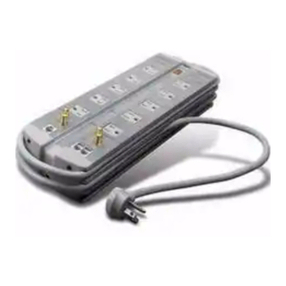
Cat No. : PP10 A 2 - 50 - C
1.2 These products are surge lters, to be installed between
mains GPO and the power cord of the equipment to be
protected against transient overvoltages.
They provide all-mode protection, in three stages. The rst
stage is metal oxide varistors, followed by an LC lter stage
and a nal metal oxide stage engineered to minimise the let
through voltage.
Load Current
Plug Type
No. of Outlets
Imax
Options
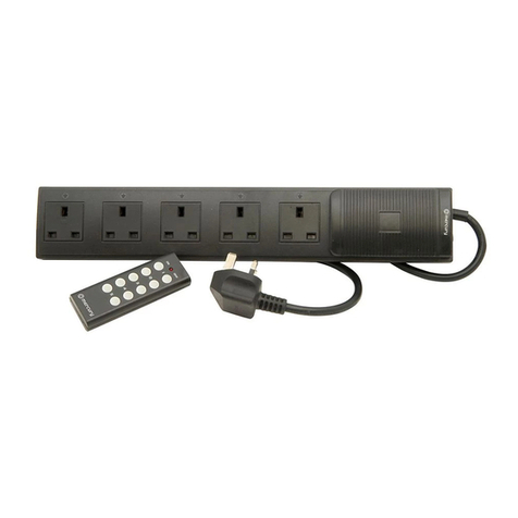
Figure 1 - PP10A2-50
2. Caution
2.1 Do not use near water or outdoors.
2.2 If the cord or the lter are damaged the lter should not be used.
In the event either is damaged, the unit should be returned to
Novaris for replacement.
2.3 Do not use the device above its rated current or power.
2.4 The unit should be placed in a location such that it, its cord and
the equipment it is protecting do not cause any safety risk.
3. Specications
3.1 Electrical Charactistics
Modes of Protection: (L-N, L-PE, N-PE)
Nominal Voltage: 230V/50Hz
Maximum Continious Voltage: 275V/50Hz
Maximum Surge Current: 19kA or 50kA
Protection Level 3kA 8/20us: <360V
Earth Leakage Current: <200uA
Maximum Voltage Drop: <1% of nominal
voltage
Aggregate Energy 5400 Joules
3.2 Dimensions
Two outlets: 160x140x60 mm
Four outlets: 210x140x60 mm
Six outlets: 260x140x60 mm
Eight outlets, rack mounted: 484x44x220 mm
4. Installation
4.1 This lter is designed to be plugged into a mains GPO. The
equipment to be protected needs to be plugged into one of the
devices sockets.
4.2 Any other cords (such as ethernet or telephone) from the
equipment to be protected should be protected as well. Plug in
surge lters are available with protection for communication
equipment included.
4.3 The unit should be placed in a location such that it, its cord and
the equipment it is protecting do not cause any safety risk. Risks
associated include but not limited to tripping on the cord, or the
unit and equipment falling on people.
4.4 PP10A8-19 feature a earth stud that should be electrically
connected to the rack earth. Use a 6mm ring lug between the
two at washers to connect a length of wire to the unit. Do not
undo the second nut.
5. Operation
5.1 Two LED indicators are present on all models. The ‘Power’
LED indicates the device has power at its input. The ‘Status’
LED indicates the device is operating normally.
5.2 A fault condition is indicated by the ‘Power’ LED being
lit and the ‘Status’ LED extinguished. If this happens
the device should be returned to Novaris for repair or
replacement.
5.3 In the event the unit is overloaded, the resettable fuse on the
left hand side of the unit will pop out. If this occurs, the
cause of the overload should be found and removed. Once
this has been performed, the fuse can be depressed to reset
the unit for normal operation.


