Novasom M7 Instructions for use
NOVAsomM7
Hardware User Manual
N.M7-250518-HUM-M7-V1.2 Page 1 of 25
www.novasomindustries.com
urope | Asia | America
NOVAsomM7
Hardware User Manual

NOVAsomM7
Hardware User Manual
N.M7-250518-HUM-M7-V1.2 Page 2 of 25
www.novasomindustries.com
urope | Asia | America
Index
1 : Welcome to the NOVAsom M7 world.......................................................................................................... 4
2 : Features........................................................................................................................................................ 5
3 : Description.................................................................................................................................................... 7
4 : Connectors description and Configuration .................................................................................................. 8
4.1 Connectors list and function.................................................................................................................... 8
4.2 Connectors pinout................................................................................................................................. 10
4.3 J9 xpansion Connector pinout ............................................................................................................. 11
4.6 J7 Audio Connector pinout.................................................................................................................... 12
5 : lectrical characteristic............................................................................................................................... 13
5.1 Absolute maximum ratings.................................................................................................................... 13
5.2 Recommended operating conditions .................................................................................................... 14
5.3 Power consumption and power dissipation.......................................................................................... 14
5.4 USB relevant standards ......................................................................................................................... 14
6 : Operational characteristics......................................................................................................................... 14
6.1 : Development system requirements.................................................................................................... 14
6.2 : The NOVAsom M7 console.................................................................................................................. 16
6.3 : The first boot ....................................................................................................................................... 17
6.4 : Connections to J9 ................................................................................................................................ 19
6.5 : Connecting an external battery to the NOVAsom M7 board.............................................................. 19
6.6 : Developing a NOVAsom M7 extension board ..................................................................................... 20
7 : Board outline and mechanical dimensions ...........................................Errore. Il segnalibro non è definito.
8 : Trobleshooting............................................................................................................................................ 23
9 : Contacts...................................................................................................................................................... 25
10 : Document revisions, references and notes.............................................................................................. 25
10.1 Document revisions............................................................................................................................. 25
10.2 xternal references.............................................................................................................................. 25
10.3 Notes ................................................................................................................................................... 25

NOVAsomM7
Hardware User Manual
N.M7-250518-HUM-M7-V1.2 Page 3 of 25
www.novasomindustries.com
urope | Asia | America
Index of Tables
Table 1 : Connectors list .................................................................................................................................... 9
Table 2 : Connectors pinout ............................................................................................................................ 11
Table 3 : Absolute maximum ratings............................................................................................................... 13
Table 4 : Recommended operating conditions ............................................................................................... 14
Table 5 : Groups recommendations ................................................................................................................ 21
Table 6 : Troubleshooting................................................................................................................................ 24
Index of Figures
Figure 1 : NOVAsom M7 top view ..................................................................................................................... 8
Figure 2 : NOVAsom M7 bottom view............................................................................................................... 9
Figure 3 : J9 Details.......................................................................................................................................... 11
Figure 4 : Audio connector detail, default OMTP........................................................................................... 12
Figure 5 : The NOVAsom M7 first boot ........................................................................................................... 18
Figure 6 : Power input section......................................................................................................................... 22

NOVAsomM7
Hardware User Manual
N.M7-250518-HUM-M7-V1.2 Page 4 of 25
www.novasomindustries.com
urope | Asia | America
1 : Welcome to the NOVAsom M7 world
Thank you for choosing this NOVAsom Industries product.
Please carefully read this user guide before using the device for the first time to ensure safe and proper
use.
In particular note that :
•Contents and illustrations may differ from your device, depending on the software version, OS
version or product improvements that NOVAsom Industries judges important, and are subject to
change without prior notice. Always stay updated visiting www.novasomindustries.com .
•Descriptions are based on the device default settings.
•Modifying the device, the device’s operating system or installing software from unofficial sources
may damage the device itself and lead to data corruption or data loss, or worst, hardware damage.
Such actions will violate your NOVAsom Industries license agreement and void your warranty.
•Always use genuine NOVAsom Industries accessories. The supplied items are designed only for this
device and may not be compatible with other devices. To have further information on this specific
item visit www.novasomindustries.com .
•Default applications on the device are subject to updates, and support for these applications may
be withdrawn without prior notice. If you have any questions about an application provided with
the device, please contact NOVAsom Industries at www.novasomindustries.com .
•Software, audio, wallpaper, images, and other media supplied with your device or found in the
appropriate SDK are licensed for limited use. If you extract and use these materials for commercial
or other purposes, you may be infringing copyright laws. As a user, you are fully responsible for the
illegal use of media.
The NOVAsom M7 family is a product line from NOVAsom Industries, targeted toward the low price market
(vending, domotics, IoT, etc.) and designed to compete with low cost boards while maintaining NOVAsom
Industries high quality level.
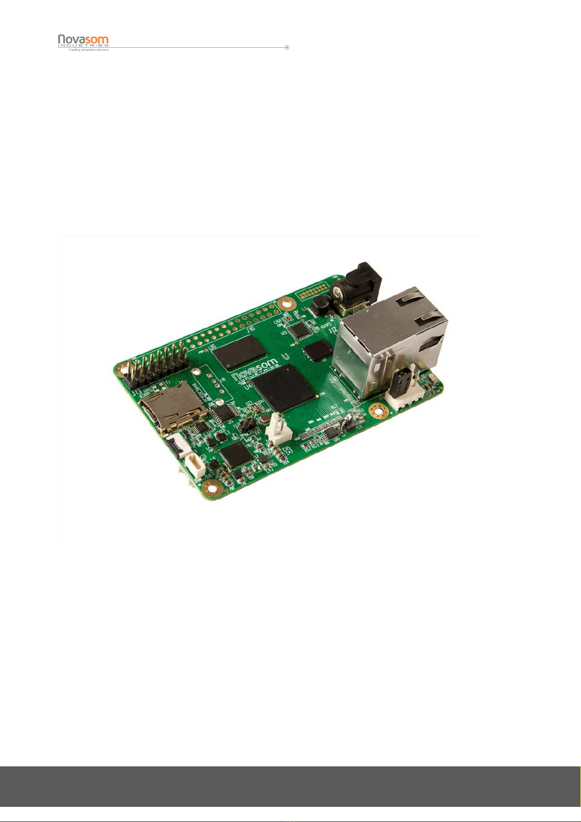
NOVAsom M7 is a very small NOVAsom board, approximately credit card size, but with all the necessary to
guarantee an immediate bootstrap, driving a display, connecting via thernet and USB.
It’s equipped with one 2.54 mm. dual row strip PI compatible for external expansions.
1 product with different configurations is available:
• NOVAsomM7C: with Rockchip® RK3328 quad A53 processor @1.6GHz, 2GB RAM DDR3L
This will vary with time, more information about product status and availability can be found visiting
www.novasomindustries.com .

NOVAsomM7
Hardware User Manual
N.M7-250518-HUM-M7-V1.2 Page 5 of 25
www.novasomindustries.com
urope | Asia | America
2 : Features
From the integrator point of view the board is a full fledged SBC, with video and communications
capabilities and requires a single supply from a wall cube or a generic external power supply.
The main characteristics of the NOVAsom M7 are:
On Board Peri herals:
•Up to 2GBytes 32 bit wide LPDDR
•1 bootable uSD slot up to 128GBytes
•1 thernet port @ 10/100 Mbit/sec.
•1 4K HDMI video output port
•1 Integrated RTC with optional external battery connector
•Audio codec and analog RGB output on dedicated expansion connector J7
•1 USB 2.0 Host connector + 1 USB 2.0 OTG connector
•1 USB 3.0 Host connector
•1 Remote IR input with connector
•1 optical SPDIF out expansion connector
•1 Power led and 1 User Driven led
•Standard 2.5mm Power Supply Jack for 6.5Vcc to 12Vcc input, central positive
•WiFi / BlueTooth module with UFL antenna connector
On Ex ansion Connectors ( J9 ):
•1 I2C @ 3.3V
•1 SPI @ 50 MHz maximum
•8 GPIO @ 3.3V
•1 Full UART @ 3.3V (TX ; RX ; RTS ; CTS )
•1 PCM AUDIO @ 3.3V
•1 x RS232
•1 x uSD/eMMC plus 3 GPIO
•1 x TX/RX only UART

NOVAsomM7
Hardware User Manual
N.M7-250518-HUM-M7-V1.2 Page 6 of 25
www.novasomindustries.com
urope | Asia | America
On IR Ex ansion Connectors ( J4 ):
•Input from IR detector ( Note 1 ) ( Note 2 )
•Output led for IR feedback ( Note 1 ) ( Note 2 )
On SPDIF Ex ansion Connectors ( J5 ):
•Output led for optical SPDIT transmitter ( Note 1 ) ( Note 2 )
Note 1 : these pins have a dedicated function and cannot be used as GPIO
Note 2 : these pins have the appropriate driver
All the pins without (Note 1) , (Note 2) or (Note 3) can be programmed as GPIO or programmed accordingly
to the functions described in table 6 and table 7 below.
The connectors J4 is normally not equipped with the pin strip.
The user has so the choice to use a male or female contact type, and to solder the strips on top or bottom
of the NOVAsom M7, use partially populated connectors or a mix of them.

NOVAsomM7
Hardware User Manual
N.M7-250518-HUM-M7-V1.2 Page 7 of 25
www.novasomindustries.com
urope | Asia | America
3 : Description
The NOVAsom M7 family is equipped with Rockchip RK3328 quad A53 processor , up to 2GByte DDR3L and
WiFi/BT, 100 Mbps thernet with magnetic connector on board and PI compatible expansion connector.
UPS-Manager© , WiFi and other options are available on request.
Visit www.novasomindustries.com , you can download 3D drawings and detailed mechanical drawing.
NOVAsomM7
Hardware User Manual
N.M7-250518-HUM-M7-V1.2 Page 8 of 25
www.novasomindustries.com
urope | Asia | America
4 : Connectors description and Configuration
4.1 Connectors list and function
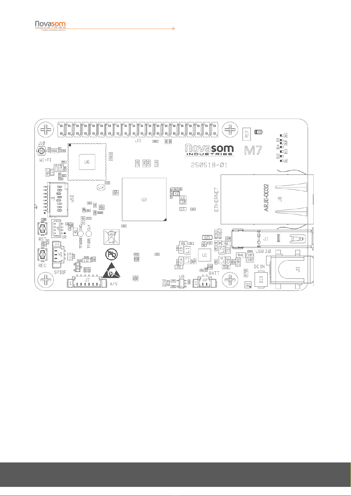
In Figure 2 you can see the
NOVAsom
M7 board connectors top placement, while in Figure 3 you can see
the
NOVAsom
M7 board connectors bottom placement
Figure 1 : NOVAsom M7 to view

NOVAsomM7
Hardware User Manual
N.M7-250518-HUM-M7-V1.2 Page 9 of 25
www.novasomindustries.com
urope | Asia | America
Figure 2 : NOVAsom M7 bottom view
In Table 1 you can see the
NOVAsom M7
board connectors and the mating connectors.
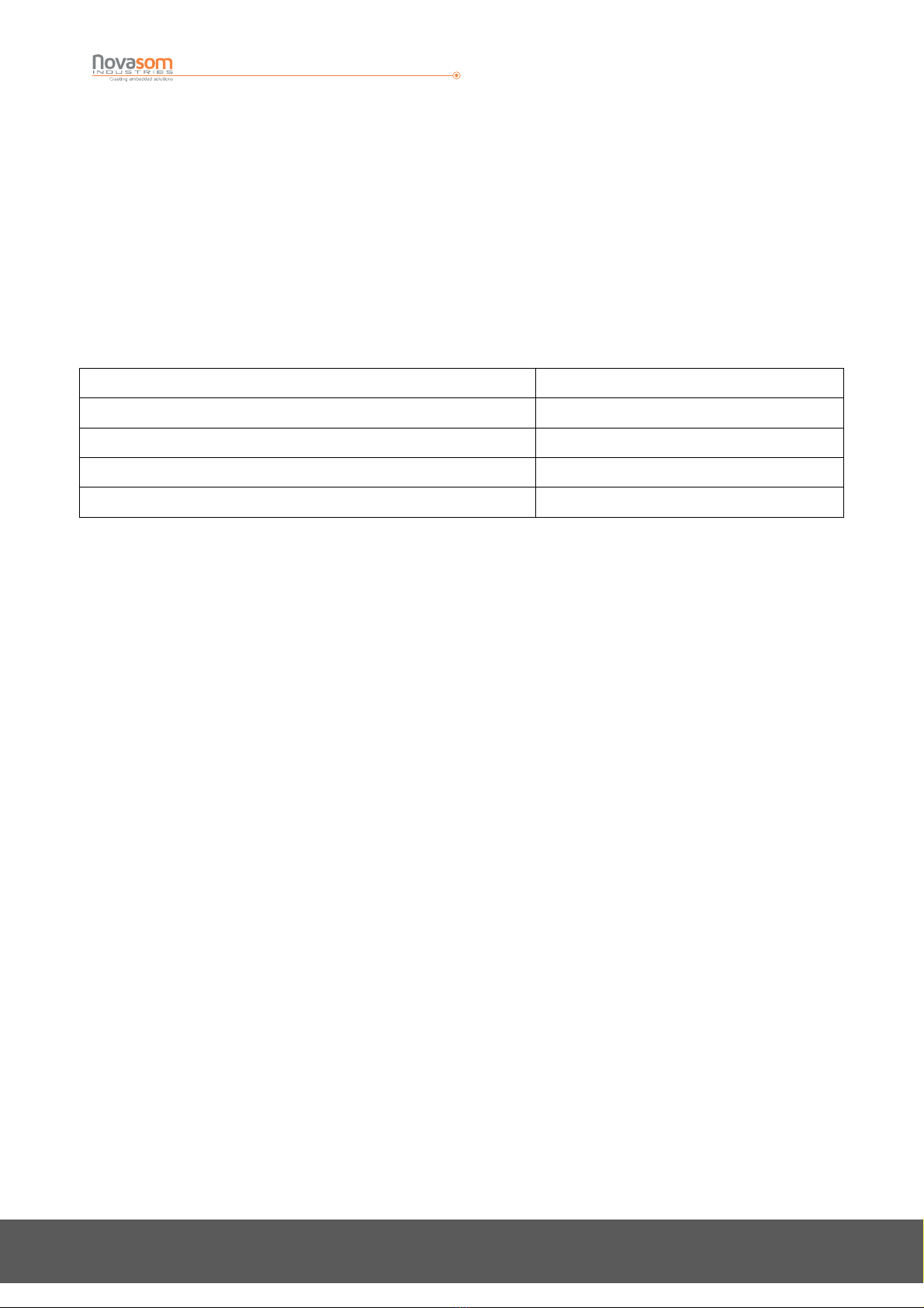
Connector Manufacturer Connector Part Number Function
J1 Molex 1051620001 µSD
J2 FCI 10104111-0001LF µUSB
J3 Molex 0484040003 USB 3.0
J4 JST BM04B-SRSS-TB(LF)(SN) IR
J5 Molex 53398-0371 SPDIF
J6 FCI 10029449-001RLF HDMI
J7 Molex 53398-0671 A/V PORT
J8 Abracon ARJE-0032 Eth+USB 2.0
J9 - - 40 pin header
J10 Hirose U.FL-R-SMT-1 UFL connector
J11 CUI PJ-002AH-SMT-TR POWER
J12 Molex 53398-0271 Battery
Table 1 : Connectors list

NOVAsomM7
Hardware User Manual
N.M7-250518-HUM-M7-V1.2 Page 10 of 25
www.novasomindustries.com
urope | Asia | America
4.2 Connectors pinout
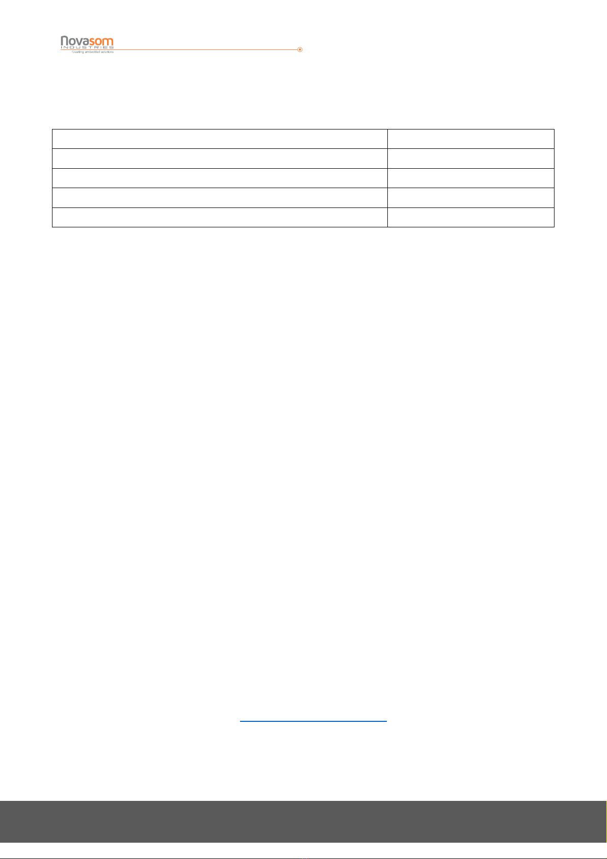
In the Table 2 you can see the NOVAsom
M7 board connectors functions and pin assignement for the non
standard parts.
Identifier Function Position Pin Function
J1 SD Card Slot Top Standard uSD card
J2 USB2.0 OTG Bottom Standard uSB
J3 USB3.0 HOST Top Standard USB 3.0
J4 IR CONNECTOR TOP 1 : LED
2 : GND
3 : IR_RX
4 : 3.3 VCC
J5 SPDIF TOP 1 : SPDIF OUT
2 : 3.3 VCC
3 : GND
J6 HDMI BOTTOM Standard HDMI
J7 A/V PORT TOP 1 : 3.3 VCC
2 : TV Out
3 : LINEOUT L
4 : LINEOUT R
5 : AUDIO MUTE
J8 ETH/USB TOP Standard Ethernet
Standard USB 2.0
J9 EXPANSION TOP
J10 WiFi / BT TOP Standard center pin
UFL connector
J11 Power In TOP Standard 2x5.5MM
center positive
connector
J12 External Battery TOP 53261 pico blade
1: Positive
2 : Negative

NOVAsomM7
Hardware User Manual
N.M7-250518-HUM-M7-V1.2 Page 11 of 25
www.novasomindustries.com
urope | Asia | America
Table 2 : Connectors inout
(*) Note : the uSD slot is 3.3V powered and has no provisions to manage the insertion or the removal of the
uSD card with power applied, and thus no SD protections equip the uSD slot.
The insertion or the removal of a uSD card with applied power may result in a permanent damage to the
card or, worst, to the NOVAsom M7 board.
The card MUST be inserted without power applied.
The presence switch that equips the uSD slot of the NOVAsom M7 board signals to the processor that a
card is in the slot, thus allowing the boot process to read the bootloader from the uSD slot.
If the card is not found when the power is applied the boot process will look in eMMC chip for a valid
bootloader code but the presence of the eMMC depends on the NOVAsom M7 board equipment.
The uSD slot is a push only operated slot.
4.3 J9 Expansion Connector pinout
Figure 3 : J9 Details

NOVAsomM7
Hardware User Manual
N.M7-250518-HUM-M7-V1.2 Page 12 of 25
www.novasomindustries.com
urope | Asia | America
4.6 J7 Audio Connector pinout
Figure 4 : Audio connector detail, default OMTP
NOVAsomM7
Hardware User Manual
N.M7-250518-HUM-M7-V1.2 Page 13 of 25
www.novasomindustries.com
urope | Asia | America
5 : Electrical characteristic
5.1 Absolute maximum ratings
Over operating free-air temperature range (unless otherwise noted)(1)(2)
VINHIGH 6.5 to 13V ( up to 18Vcc for t < 100 uSec. )
3.3V pin input voltage (2) -0.3V to 3.6V
Battery Voltage Input -0.3V to 4.7V
3.3V pin output voltage (2) -0.3V to 3.6V
Input clamp current for 3.3V pin (2) ±10mA
Table 3 : Absolute maximum ratings
(1) Stresses beyond those listed under “Absolute maximum ratings” may cause permanent damage to the board. These are stress ratings only, and
functional operation of the device at these or any other conditions beyond those indicated under “Recommended operating conditions” is not
implied. xposure to absolute-maximum-rated conditions for extended periods may affect board reliability.
(2) The input and output voltage ratings may be exceeded if the input and output current ratings are observed.
NOVAsomM7
Hardware User Manual
N.M7-250518-HUM-M7-V1.2 Page 14 of 25
www.novasomindustries.com
urope | Asia | America
5.2 Recommended operating conditions
VINHIGH 6.5V to 12.5 Vcc (up to 18Vcc for t < 100 uSec.)
3.3V pin input voltage (2) 0V to 3.3V
Battery Voltage Input 0V to 4.3V
3.3V pin output voltage (2) 0V to 3.3V
Input clamp current for 3.3V pin (2) ±2mA
Table 4 : Recommended o erating conditions
5.3 Power consumption and power dissipation
All measurements are done with an input voltage of 12V with Android 8.1 and an HDMI monitor @
1920x1080.
•Boot phase : 200 mA
•Running : 170 mA Suspend to memory : 110 mA
•Freeze to memory : 20 mA
For the details of the low power modes consult the Rockchip RK3328 Reference Manual
5.4 USB relevant standards
•
Universal Serial Bus Specification, Rev. 2.0 (Compaq, Hewlett-Packard, Intel,Lucent, Microsoft, N C,
Philips; 2000)
•
On-The-Go and mbedded Host Supplement to the USB Revision 2.0 Specification (Hewlett-Packard
Company, Intel Corporation, LSI Corporation, Microsoft Corporation, Renesas lectronics
Corporation,ST- ricsson; 2012).
6 : Operational characteristics
6.1 : Development system requirements
From the NOVAsom Industries web site
www.novasomindustries.com
the user can download the
NOVAsom SDK to ease the development process for all the NOVAsom Industries boards.
The NOVAsom M7 board is currently supported at the boot level, and there is the standard BSP support in

NOVAsomM7
Hardware User Manual
N.M7-250518-HUM-M7-V1.2 Page 15 of 25
www.novasomindustries.com
urope | Asia | America
form of device tree blob, or DTB.
The NOVAsom SDK is a virtual machine tool, running on a Fedora 20 core and based on VirtualBox.
The Virtual Machine is thus compatible with hosts based on Windows™ , MacOS™ or Linux machines.
More detailed information aboaut the installation process of the NOVAsom SDK can be found visiting the
NOVAsom Industries web site at
www.novasomindustries.com
.
Normally, for a relatively relaxed development, an I5 host with 60 GBytes of free hard disk space and
8GBytes of RAM is enough.
For very heavy developments ( as a complex 3D supported Qt file system or a Chromium X based
application ) “the bigger is better”, so more RAM you can dedicate to the Virtual Machine the faster the
Virtual Machine will run.
A more than good situation is an I7 host with 16GB of RAM and 128GB of free disk space.
For connecting to the NOVAsom M7 console you need a serial port, and considering that on modern
desktop the serial port is not present a USB to Serial adapter is probably the only choice you have.
Finally, you need a uSD written with a basic file system, and a way to physically write the uSD itself.
You can download a uSD image from the
www.novasomindustries.com
page in the NOVAsom M7
dedicated section, where you can find all the information about how to write a uSD from the NOVAsom M7
image you just downloaded using your preferred host system.

NOVAsomM7
Hardware User Manual
N.M7-250518-HUM-M7-V1.2 Page 16 of 25
www.novasomindustries.com
urope | Asia | America
6.2 : The NOVAsom M7 console
In order to use the serial console available on the NOVAsom M7 board you need a serial terminal.
GtkTerm is a good choice for Linux users, Teraterm is a nice choice for Windows™ users, it’s up to MacOS™
users to understand which kind of terminal application they need.
The NOVAsom M7 port is on pins 8 and 10 of J9 connector at 3.3V level. An external translator or an
external USB to serial converter is required. NOVAsom Industries can provide a suitable adapter ( see code
240718 ) to drive the pins adequately. A serial port with a bit rate of 115200 with no flow control and 1
stop bit is required to communicate wit the NOVAsom M7 board.
The pins from where to connect the serial port are pin 8 of J9 ( TXD from NOVAsom M7 board ) , pin 10 of
J9 (RXD to NOVAsom M7 board ) and pin 6 of J9 ( the GND connection ).
Just plug both the power supply and the serial port through the adapter and you will see the boot process
of your new NOVAsom M7 board.

NOVAsomM7
Hardware User Manual
N.M7-250518-HUM-M7-V1.2 Page 17 of 25
www.novasomindustries.com
urope | Asia | America
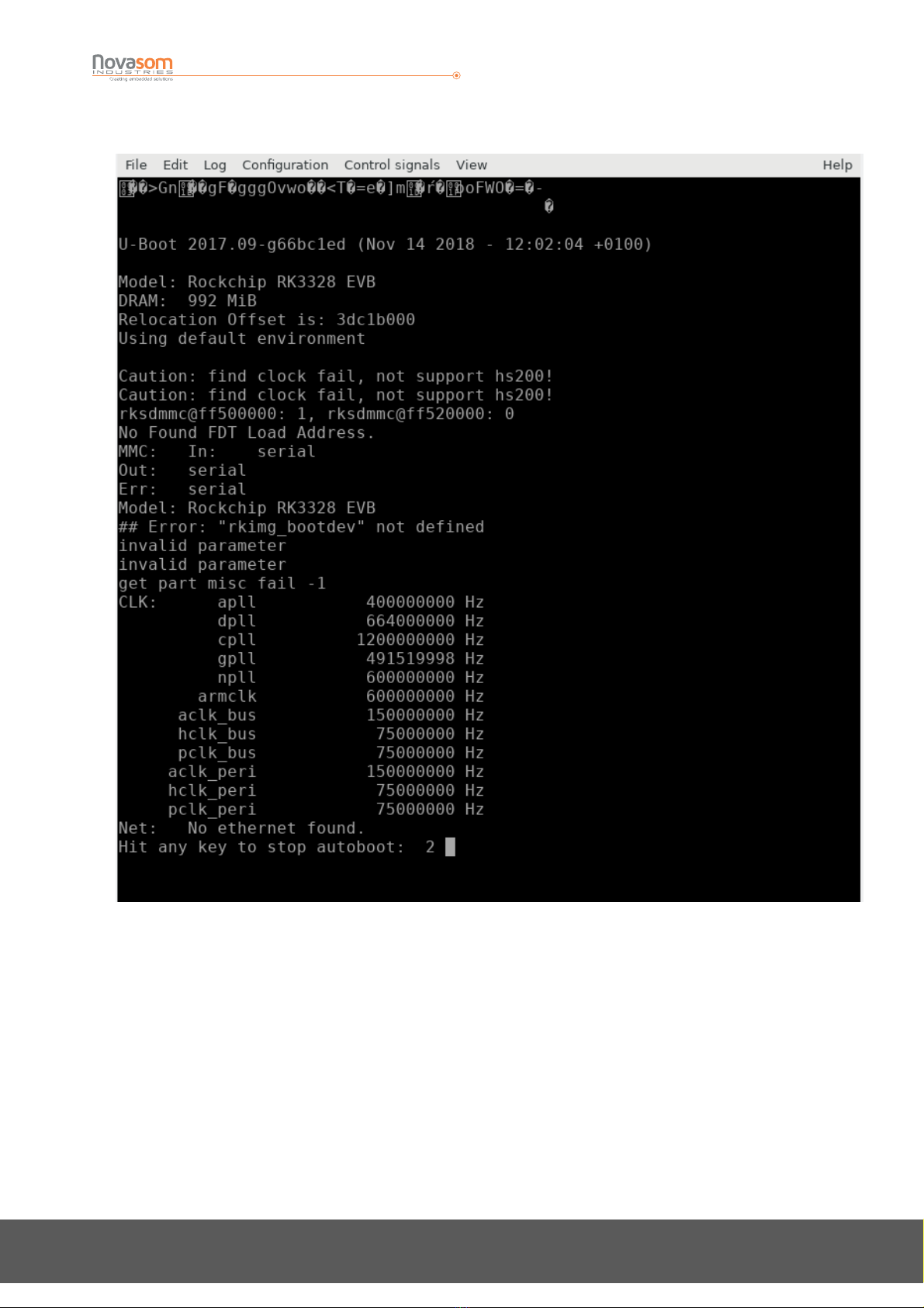
6.3 : The first boot
The steps in order to boot your NOVAsom M7 board are :
•
Create the uSD with a standard file system as described in chapter 6.1 above
•
Insert the just written uSD in the J1 slot
•
Connect the serial port to your NOVAsom M7 and a FHD capable monitor the the HDMI ( J6
connector)
•
Insert an appropriate power source chord in the J11 connector and power it on.
After just some half a second you should see on your terminal application something similar to what you
see in Figure 7 below, and this means you have your NOVAsom M7 powered up and running.
NOVAsomM7
Hardware User Manual
N.M7-250518-HUM-M7-V1.2 Page 18 of 25
www.novasomindustries.com
urope | Asia | America
Figure 5 : The NOVAsom M7 first boot
Please note : the garbage in the very first lines are due to the output messages from the Rockchip binary
distributed proprietary code during the DDR initialization, where the bit rate is set at 1.500.000 bit/sec.
After this quick initial phase the Novasom Industries boot loader is started and a more comfortable 115.200
bit/sec speed is programmed in the serial communication device.
A special note about the uSD slot : the uSD slot has not been designed to insert or remove the uSD card
with power applied, so inserting or removing a uSD card with applied power may result in a permanent
damage to the card or, worst, to the NOVAsom M7 board.
The card MUST be inserted without power applied.
The presence switch that equips the uSD slot of the NOVAsom M7 board signals to the processor that a

NOVAsomM7
Hardware User Manual
N.M7-250518-HUM-M7-V1.2 Page 19 of 25
www.novasomindustries.com
urope | Asia | America
card is in the slot, thus allowing the boot process to read the boot loader from the uSD slot.
If the card is not found when the power is applied the boot process will look in eMMC chip ( if present ) for
a valid boot loader code, but remember that the presence of the qSPI chip depends on the NOVAsom M7
board configuration.
6.4 : Connections to J9
J9 sports a lot of signals, and most of them are connected at the processor level without buffering or
protection.
Although the processor is quite protected on over and under voltages, care should be taken in order to
avoid to stress the processor outside the recommended operating conditions, or permanent damages will
result on the processor itself.
It’s quite common to overtake a ringing digital signal that stresses the processor outside the recommended
operating conditions, so if you are in doubt use dump series resistors in the order of 1 KΩ for input signals.
In the table 2 the signals are named as the standard DTB factory functions, and the colored functions are
the functions provided by the standard DTB factory functions.
You can find all the information on how to change a pin function visiting the
www.novasomindustries.com
page in the NOVAsom M7 dedicated section, where you can find a lot of
application notes and already developed tools and examples.
6.5 : Connecting an external battery to the NOVAsom M7 board
The connector J12 is minded to connect a 3.7V external battery.
The external battery will be used on systems that need to be powered by an external battery.
On the other hand, the battery can be of a rechargeable type ( LiIon or Lithium coin cell ) and will be
charged with 450 mA from the 5V supply.
Care should be taken to connect the correct battery ( a 3.7V battery is requested, higher voltages will
immediately destroy your NOVAsom M7 board ) and connect the battery in the correct way, where the pin
1 of J2 is the positive and the pin 2 is the negative. A power inversion can permanently damage the battery
or, worst, damage your NOVAsom M7 board.

NOVAsomM7
Hardware User Manual
N.M7-250518-HUM-M7-V1.2 Page 20 of 25
www.novasomindustries.com
urope | Asia | America
6.6 : Developing a NOVAsom M7 extension board
The RK3328 contains a limited number of pins, most of which have multiple signal options. These signal to
pin and pin to signal options are selected by the input/output multiplexer called IOMUX.
The IOMUX is also used to configure other pin characteristics, such as voltage level, drive strength, and
hysteresis.
Due to this, all the I/O pins on J9 behave as input at power up, and until the bootloader or the kernel are up
and running, they are substantially configured as input.
All the inputs have an internal 100kΩ pull up to the VCC rail, whichever the VCC is.
Keeping this in mind, all the pins that are configured to be an output needs a pull down resistor in the
range of 15kΩ in order to keep the particular signal at the low level, if needed.
This is true for all the I/O pins marked with the green or orange box in Table 3 for J19 and Table 4 for J13.
Conversely, all the pins marked with the yellow box in Table 3 and Table 4 doesn’t need external pull up or
pull down, but require correct impedance matching depending of the line characteristics of the function
the pin is associated to, so you should observe the basic recommendation in Table 10.
Table of contents
Popular Single Board Computer manuals by other brands


VersaLogic
VersaLogic Tetra VL-EPC-2700 Hardware reference manual

Octagon
Octagon PC-600 user manual

Vox Technologies
Vox Technologies EM586 manual

Texas Instruments
Texas Instruments TMS320DM335 user guide

Premier Farnell
Premier Farnell Embest SBC-EC8800 user manual

OLIMEX
OLIMEX A13-OLinuXino-MICRO user manual

SBS Technologies
SBS Technologies V5C Technical manual

Lanner electronics
Lanner electronics EM-561 Series user manual

MicroSys Electronics
MicroSys Electronics miriac SBC-LS1028A user manual

IEI Technology
IEI Technology Rocky-3702EV user manual

Boser
Boser HS-6036 user manual

DFI
DFI GM341-GHF installation guide