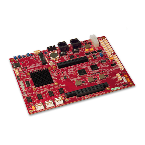
PCM-072/phyCORE-AM64xx System on Module
© PHYTEC America L.L.C. 2022 6
Figure 22. RJ45 Reference Schematic ................................................................................................................................... 58
Figure 23. RGMII PHY Reference Schematics........................................................................................................................ 61
Figure 24. PCIe Reference Schematics.................................................................................................................................. 65
Figure 25. Layout example of a ground cutout. The top image shows a filter, and the bottom image shows the ground
plane cutout beneath it. ....................................................................................................................................................... 71
Figure 26. USB-HUB Reference Schematic............................................................................................................................ 72
Figure 27. USB 3.1 Connector Reference Schematic ............................................................................................................ 73
Figure 28. JTAG Reference Schematic................................................................................................................................... 88
Figure 29. UART0 to USB Reference Schematic.................................................................................................................... 90
Figure 30. Simple UART0 Reference Schematic.................................................................................................................... 91
1.2 List of Tables
Table 1 Abbreviations and Acronyms used in this Manual ........................................................................ 10
Table 2 Signal Types Used in this Manual ................................................................................................... 11
Table 3 Technical Specifications..................................................................................................................20
Table 4 Recommended Operating Conditions for the Input and Output Power Domains........................ 20
Table 5 Solder Jumper Settings ...................................................................................................................21
Table 6 Voltage Domain Configurations ...................................................................................................... 22
Table 7 phyCORE-AM64xx Connector X1, Column A Pinout ..................................................................... 25
Table 8 phyCORE-AM64xx Connector X1, Column B Pinout ..................................................................... 27
Table 9 phyCORE-AM64xx Connector X1, Column C Pinout ..................................................................... 28
Table 10 phyCORE-AM64xx Connector X1, Column D Pinout ................................................................... 30
Table 11 Thermal Management Parts...........................................................................................................32
Table 12 External Supply Voltages...............................................................................................................34
Table 13 Reset Pin Description ....................................................................................................................37
Table 14 GPMC Signal Connections at the phyCORE-Connector.............................................................. 41
Table 15 MMC1 Connections at the phyCORE-Connector.......................................................................... 44
Table 16 phyCORE-AM64xx MMC1 Layout Characteristics........................................................................ 44
Table 17 BOOTMODE Description................................................................................................................46
Table 18 MCAN Connections at the phyCORE-Connector ......................................................................... 47
Table 19 Ethernet PHY Default Strapping Configuration............................................................................ 49
Table 20 Ethernet Connections at the phyCORE-Connector...................................................................... 49
Table 21 IEP Connections at the phyCORE-Connector .............................................................................. 52
Table 22 phyCORE-AM64xx CPSW_ETH0 Layout Characteristics ............................................................ 53
Table 23 phyCORE-AM64xx RGMII Timing Requirements.......................................................................... 54
Table 24 phyCORE-AM64xx PRG0_RMGII1 Trace Length Characteristics................................................ 55
Table 25 phyCORE-AM64xx PRG0_RMGII2 Trace Length Characteristics................................................ 55
