Novatek-electro PEF-320 User manual
«NOVATEK-ELECTRO» Ltd
Intelligent industrial electronics
UNIVERSAL AUTOMATIC
ELECTRONICPHASE SWITCH
PEF-320
OPERATING MANUAL
Quality control system on the development and production complies with requirements
ISO 9001:2015
Dear customer,
Company NOVATEK-ELECTRO LTD. thanks you for purchasing our products.
You will be able to use properly the product after carefully studying the Operating Manual.
Keep the Operating Manual throughout the service life of the product.
Odessa, Ukraine www.novatek-electro.com

~ 2 ~
PEF-320
NOVATEK-ELECTRO
ATTENTION! ALL REQUIREMENTS OF THIS OPERATING MANUAL ARE COMPULSORY TO BE MET!
WARNING! –PRODUCT TERMINALS AND INTERNAL COMPONENTS ARE UNDER
POTENTIALLY LETHAL VOLTAGE
TO ENSURE THE PRODUCT SAFE OPERATION IT IS STRICTLY FORBIDDEN THE
FOLLOWING:
TO CARRY OUT MOUNTING WORKS AND MAINTENANCE WITHOUT DISCONNECTING THE
PRODUCT FROM THE MAINS;
TO OPEN AND REPAIR THE PRODUCT INDEPENDENTLY;
TO OPERATE THE PRODUCT WITH MECHANICAL DAMAGES OF THE CASE.
IT IS NOT ALLOWED WATER PENETRATION ON TERMINALS AND INTERNAL ELEMENTS OF THE
PRODUCT.
During operation and maintenance the regulatory document requirements must be met, namely:
–Regulations for Operation of Consumer Electrical Installations;
–Safety Rules for Operation of Consumer Electrical Installations;
–Occupational Safety when in Operation of Electrical Installations.
Installation, adjustment and maintenance of the product must be performed by qualified personnel having
studied this Operating Manual.
In compliance with the requirements of this Operating Manual and regulations the product is safe for
use.
~ 3 ~
NOVATEK-ELECTRO
PEF-320
This operation manual is intended for description, principle of work, construction, mode of work and
maintenance of the Universal automatic electronicphase switch PEF-320 (further in text as PEF-320 or
the device).
PEF-320 meets the requirements of:
EN 60947-1;
EN 60947-6-2; EN 55011;
IEC 61000-4-2.
Harmful substances in concentration more than allowed are absent.
Terms and abbreviations:
AR is automatic reclosing;
OUTPUT is terminals for load connection, also LED indicators showing the phase connected to load (L1,
L2, L3)
The term "Normal voltage" means that the voltage value does not exceed the threshold limit values set by the
User.
1. DESCRIPTION AND OPERATION
1.1. Application
The PEF-320 universal automatic electronic phase switch is designed to supply an industrial and domestic
single phase 230 V, 50 Hz load from three-phase four-wire mains 3х400+N in order to maintain uninterrupted
power supply of essential single-phase loads and protect them against unallowable voltage variations in the
mains.
According to the voltage presence and voltage quality on the phases, the PEF-320 will automatically select
the optimum phase in limits range set by user and switch the single phase load supply to this phase.
It is possible to connect to one of the phases of the electric generator, inverter.
The maximum and minimum voltage limits are set by user.
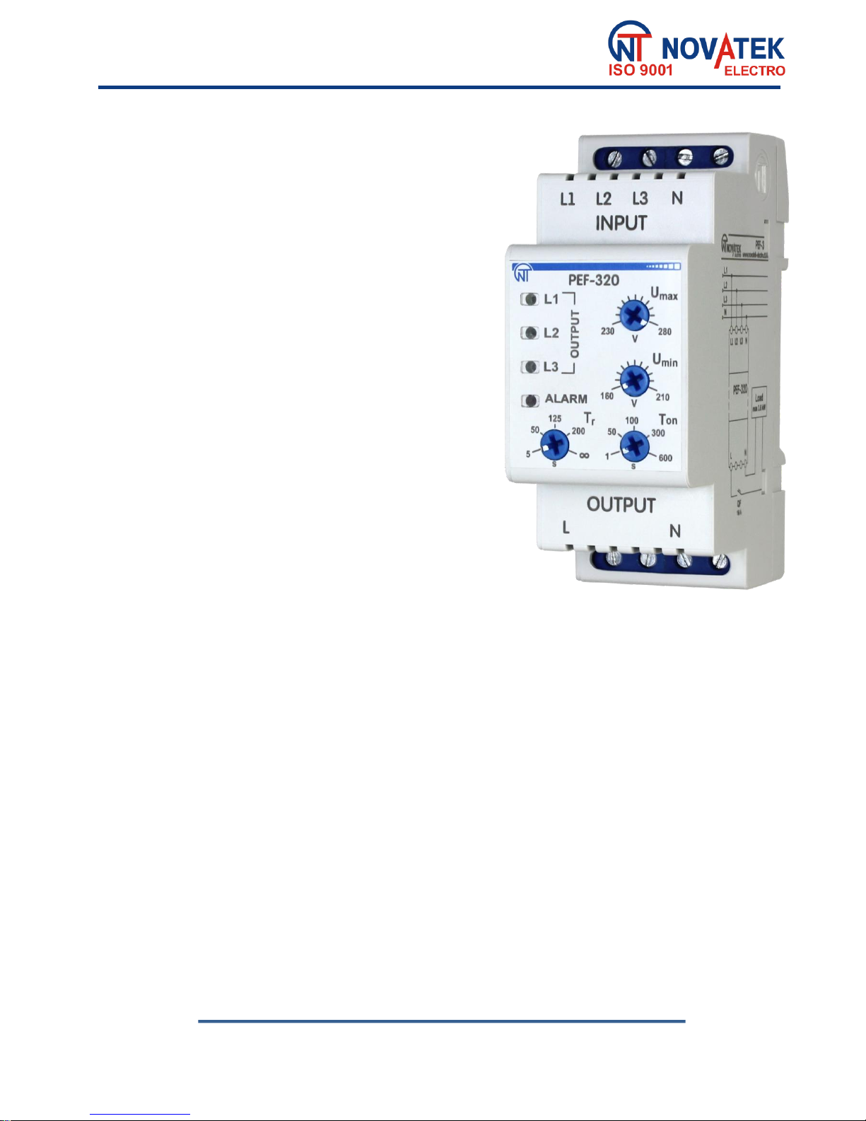
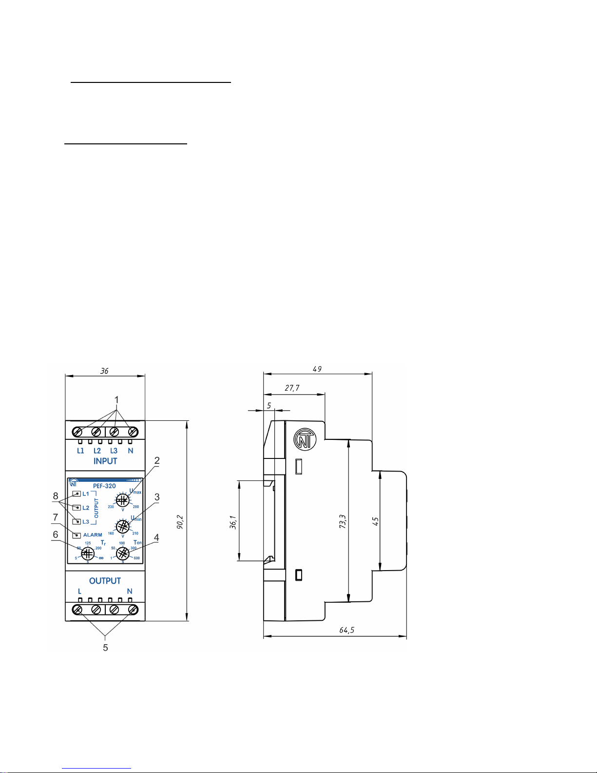
1.2. Controls, overall and mounting dimensions of PEF-320
Controls, overall and mounting dimensions of PEF-320 are shown in Fig. 1.
1–terminals for power
supply;
2–knob for threshold trip
setting for maximum voltage
(Umax);
3–knob for threshold trip
setting for minimum voltage
(Umin);
4–knob for automatic
reclosing time setting (Тon);
5–load terminals;
6–knob for time setting of
return to the priority phase
(Тr);
7–alarm LED indicator
(ALARM);
8–LED indicators of phases
(L1, L2, L3).
Fig. 1 –Controls, overall and mounting dimensions of PEF-320
1.3. Operation conditions
The device is intended for operation in the following conditions:
–Ambient temperature: from minus 35 to +55 °С;
–Atmospheric pressure: from 84 to 106.7 kPa;
–Relative humidity (at temperature of +25 °С): 30 … 80 %.

~ 4 ~
PEF-320
NOVATEK-ELECTRO
If the temperature of the device after transportation or storage differs from the ambient temperature at which it is
supposed to be operated, then before connecting to the mains keep the device under the operating conditions
within two hours (because of condensation may be on the device elements).
ATTENTION! The device is not intended for operation in the following conditions:
–Significant vibration and shocks;
–High humidity;
–Aggressive environment with content in the air of acids, alkalis, etc., as well as severe contaminations
(grease, oil, dust, etc.).
2. TECHNICAL SPECIFICATIONS
The basic technical specifications are given in Table 1.
Table 1.
Designation
Value
Nominal phase voltage, V
230
Operating capability voltage, on single phase, V
120
Mains frequency, Hz
45 –55
Trip threshold for Umin, V
160 –210
Trip threshold for Umax, V
230 –280
Time delay range for return to the priority phase (Tr), sec *
5 –200
Time delay range of reclosing (Ton), sec
1 –600
Fixed time delay of switching over (switching off) for Umin, sec
12
Time of switching over to reserve phases, sec, not more
0.2
Hysteresis (reset coefficient) on voltage, V
5 –6
Accuracy of threshold trip, V
±3
Maximum switched current (cos φ=1) of additional relay output contacts, A
16
Maximum switched current (cos φ=0.4) of additional relay output contacts, A
5
Device operating capability phase voltage, V
400
Short time allowable operating capability maximal phase voltage, V
450
Power consumption (under load), W, not more than
1.2
Protection degree of the front panel
IP 40
Protection degree of terminals block
IP 20
Climatic version
NF 3.1
Electric shock protection class
II
Pollution rate
II
Category of overload
II
Device scope
Control and distribution device
Construction type (installation)
On standard DIN-rail, 35 mm
Cross-section of connection terminal wires, mm2
0.5 –1.5
Screw torque of terminal clams, N*m
0.4
Service life of output contacts:
-under load 16 A, operations, not less than
-under load 5 A, operations, not less than
50 000
100 000
Overall dimensions H*B*L, mm
90.2*36*64.5
Weight, kg, not more than
0.15
The device remains operational capability in any position in space
Housing material - self-extinguishing plastic
* –If knob Тris in position "" there is no return to the priority phase
3. DESIGN AND PRINCIPLE OF OPERATION
The electronic phase switch PEF-320 is a microprocessor-based digital device.
The user should make settings of the trip threshold limits of the PEF-320 - the minimum and maximum
voltage values at which the device trips and switches over to the backup phase (switches off the load).
The glow of one of the green LEDs L1, L2, L3 on the front panel indicates the phase to which the load is
connected.
PEF-320 has three independent inputs, terminal L1 (priority phase) and L2, L3 (backup phases).

~ 5 ~
NOVATEK-ELECTRO
PEF-320
With normal voltage on all phases, (L1, L2, L3), the load will be connected to phase L1. If the voltage value
L1 goes beyond the thresholds, the PEF-320 will check the L2 phase and connect the load through it. If the
voltage value L2 is out of the trip thresholds, the PEF-320 will connect the load to phase L3. If the voltage on
the backup phases does not correspond to the set thresholds, the load is switched off.
Switching to the phase with unallowable parameters will not be performed.
After the load had been switched to the backup phase and the voltage parameters had been restored on
the priority phase, the load will be switched to the priority phase after the return time set by the User.
ATTENTION! If during the countdown of the return time, the voltage in the priority phase goes
beyond the thresholds, then the countertimer will be reset.
If Tr is in the “∞”position, then the return to the priority phase will be performed only when the voltage in
the backup phase exceeds the specified thresholds.
In the case when the voltage supplied to the load decreases below the threshold of the minimum allowable
voltage, the switching over or disconnection of the load will be performed with a time delay of 12 seconds. If the
voltage exceeds the threshold of the maximum allowable voltage or decreases by 30 V lower than the threshold
of the minimum allowable voltage, the load switching over or disconnection will be performed with time delay of
0.2 seconds.
When the load is disconnected, the PEF-320 continues to perform the voltage control for all phases.
After restoring the voltage parameters at one of the phases within acceptable limits, the PEF-320 will switch
the load to this phase during the time of AR.
4. THE INTENDED USE
4.1. Preparation for operation
4.1.1. Preparation for connection:
unpack the device and check the device for damage absence after transportation; in case of such
damages detection, contact the supplier or the manufacturer;
carefully study the Operation Manual (pay special attention to the diagram of the device connection
to power).
4.1.2. Device connection
ATTENTION! THE DEVICE IS NOT INTENDED FOR SWITCHING A LOAD IN CASE OF SHORT
CIRCUITS. IN THE CIRCUIT OF OUTPUT CONTACTS OF THE DEVICE IT IS NECESSARY TO INSTALL
THE CIRCUIT BREAKER (FUSE) WITH CUT-OFF CURRENT NOT OVER 16 A OF CLASS B.
ATTENTION! ALL CONNECTIONS MUST BE PERFORMED WHEN THE DEVICE IS DE-ENERGIZED.
Error when performing the installation works may damage the device and connected devices.
To ensure the reliability of electrical connections the flexible (stranded) wires with insulation for voltage of at
least 450 V should be used, the ends of which it is necessary to be striped of insulation for 5±0.5 mm and
tightened with bootlaces. It is recommended to use the wire with cross-section of at least 1 mm2. Wires
fastening should exclude mechanical damage, twisting and abrasion of the wire insulation.
IT IS NOT ALLOWED TO LEAVE EXPOSED PORTIONS OF WIRE PROTRUDING BEYOND THE
TERMINAL BLOCK.
For a reliable contact, tighten the terminal screws with the force indicated in Table 1.
When reducing the tightening torque, the junction point is heated, the terminal block may be melted and
wire can burn. If you increase the tightening torque, it is possible to have thread failure of the terminal block
screws or the compression of the connected wire.
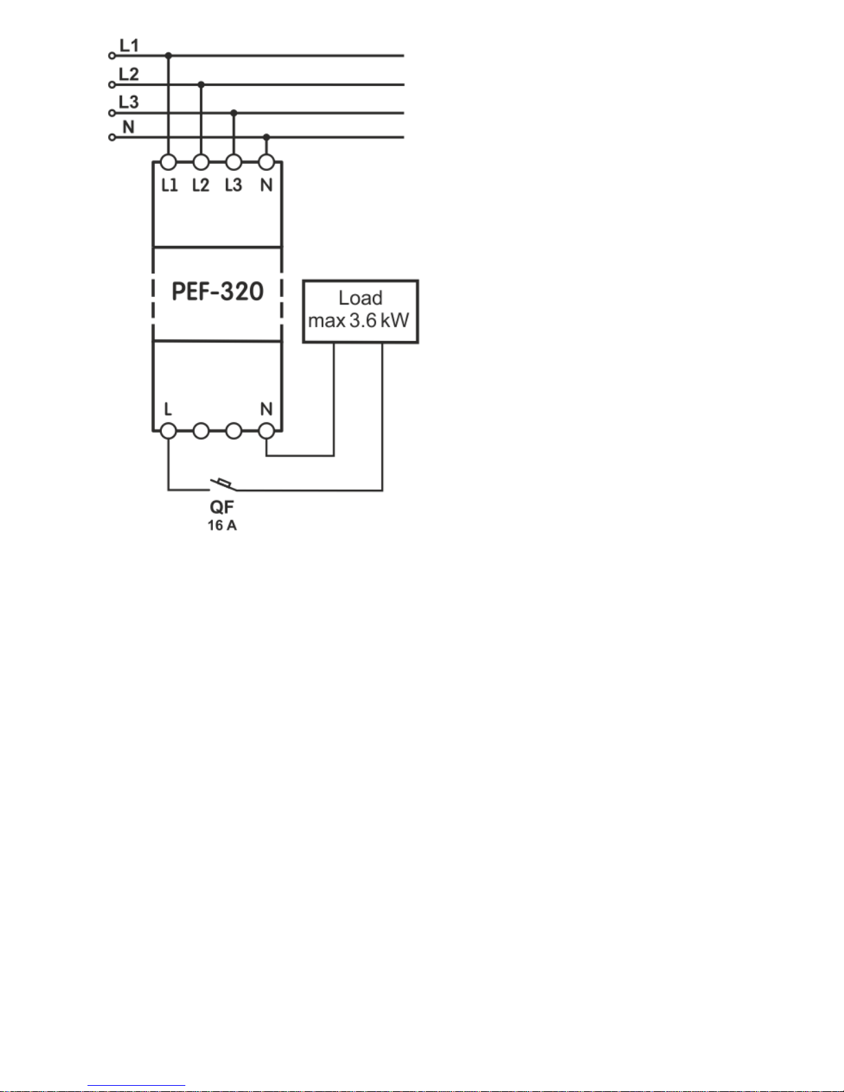
4.1.2.1. Connect the device according to the diagram shown in Fig. 2.
~ 6 ~
PEF-320
NOVATEK-ELECTRO
QF –circuit breaker 16 А.
Fig. 2 –Connection Diagram of PEF-320
4.1.2.2. Set the device trip thresholds with the help of knobs: Umax, Umin, Тr and Тon.
ATTENTION! Do not use excessive force when performing setting operations.
Umax –is the maximum voltage threshold.
Umin –is the minimum voltage threshold.
Тon –is the time for the automatic reset of the load after the restoration of the voltage parameters at one of
the phases, as well as the time of the load initial switching on after energizing the PEF-320 device.
For refrigerators, air conditioners and other compressor equipment, Ton is recommended to be set within
180 –600 s, for other devices - according to their operating instructions.
Тr –is the time of return to the priority phase.
After the setting the threshold values, the device is ready for operation with the load.
It is allowed to change the thresholds values Umax, Umin, Tr and Ton during the device operation
with observing the safety regulations.
4.2.Intended use
After connection to power supply and setting the parameters, the PEF-320 is ready for operation.
The glow of one of the LED indicators L1, L2, L3 on the front panel shows the phase to which the load is
connected. If the load is disconnected from all three phases, the ALARM indicator will light up.
If the voltage for all three phases does not correspond to the set thresholds, the load will be switched off
and the ALARM indicator will light up.
In the case when several PEF-320 devices are used in the line, to avoid the phase overloading, it is
recommended to select different phases as the priority one for different groups of consumers.

~ 7 ~
NOVATEK-ELECTRO
PEF-320
5. MAINTENANCE
5.1. Safety precautions
THE TERMINALS AND THE DEVICE INTERNAL ELEMENTS CONTAINS POTENTIALLY
LETHAL VOLTAGE.
DURING MAINTENANCE IT IS NECESSARY TO DISABLE THE DEVICE AND CONNECTED
DEVICES FROM THE MAINS.
5.2. Maintenance of the device must be performed by the skilled professionals.
5.3. Recommended frequency of maintenance is every six months.
5.4. Maintenance Procedure:
1) Check the connection reliability of the wires, if necessary, clamp with the force specified in Table 1;
2) Visually check the integrity of the housing, in case of detection of cracks and damages take the device
out of service and send for repair;
3) If necessary, wipe the front panel and the housing of the device with cloth.
Do not use abrasives and solvents for cleaning.
6. SERVICE LIFE AND MANUFACTURER WARRANTY
6.1. The lifetime of the device is 10 years. Upon expiration of the service life, contact the manufacturer.
6.2. Shelf life is 3 years.
6.3. Warranty period of the device operation is 5 years from the date of sale.
During the warranty period of operation (in the case of failure of the device) the manufacturer is responsible
for free repair of the device.
ATTENTION! IF THE DEVICE HAS BEEN OPERATED WITH THE VIOLATION OF THE
REQUIREMENTS OF THIS USER MANUAL, THE USER WILL LOSE THE RIGHT TO WARRANTY
MAINTENANCE.
6.4. Warranty service is performed at the place of purchase or by the manufacturer of the device.
6.5. Post-warranty service of the device is performed by the manufacturer at current rates.
6.6. Before sending for repair, the device should be packed in the original or other packing excluding
mechanical damage.
7. TRANSPORTATION AND STORAGE
The device in the original package is permitted to be transported and stored at the temperature from minus
45 to +60 °C and relative humidity of no more than 80 %.
8. ACCEPTANCE CERTIFICATE
PEF-320 has been manufactured and accepted in accordance with the requirements of valid technical
documentation and classified as fit for operation.
Head of QCD Date of manufacture
_____________ _____________
Seal

~ 8 ~
PEF-320
NOVATEK-ELECTRO
9. CLAIMS DATA
You are kindly requested, in case of the device return and transfer it to the warranty (post-warranty) service
please indicate detailed reason for the return in the field of the claims data.
_______________________________________________________________________________
_______________________________________________________________________________
The Company is grateful to you for the information about the quality of the device and suggestions for its operation.
For all questions, please contact the manufacturer:
NOVATEK-ELECTRO Ltd,
59, Admiral Lazarev Str. ,
Odessa, 65007, Ukraine.
Tel.: +38 (048)738-00-28,
Tel./fax: +38 (0482) 34-36-73.
www.novatek-electro.com
Date of sale: __________
VN181029
Table of contents
Other Novatek-electro Switch manuals


