Novatek-electro PEF-319 User manual

«NOVATEK-ELECTRO» Ltd
Intelligent industrial electronics
UNIVERSAL AUTOMATIC ELECTRONIC PHASE SWITCH
PEF-319
PEF-319-30
OPERATING MANUAL
Quality control system on the development and production complies with requirements ISO 9001:2015
Dear customer,
Company NOVATEK-ELECTRO LTD thanks you for purchasing our products.
You will be able to use properly the product after carefully studying the Operating Manual.
Keep the Operating Manual throughout the service life of the product.
Review the Operating manual before using the unit
Odessa, Ukraine www.novatek-electro.com

~ 2 ~
PEF-319
NOVATEK-ELECTRO
ATTENTION! ALL REQUIREMENTS OF THIS OPERATING MANUAL ARE COMPULSORY TO BE MET!
WARNING! –PRODUCT TERMINALS AND INTERNAL COMPONENTS ARE UNDER
POTENTIALLY LETHAL VOLTAGE
TO ENSURE THE PRODUCT SAFE OPERATION IT IS STRICTLY FORBIDDEN THE
FOLLOWING:
TO CARRY OUT MOUNTING WORKS AND MAINTENANCE WITHOUT DISCONNECTING THE
PRODUCT FROM THE MAINS;
TO OPEN AND REPAIR THE PRODUCT INDEPENDENTLY;
TO OPERATE THE PRODUCT WITH MECHANICAL DAMAGES OF THE CASE.
IT IS NOT ALLOWED WATER PENETRATION ON TERMINALS AND INTERNAL ELEMENTS OF THE
PRODUCT.
During operation and maintenance the regulatory document requirements must be met, namely:
–Regulations for Operation of Consumer Electrical Installations;
–Safety Rules for Operation of Consumer Electrical Installations;
–Occupational Safety when in Operation of Electrical Installations.
ATTENTION! THE DEVICE IS NOT INTENDED TO BE USED FOR LOAD COMMUTATION IN CASE OF SHORT
CIRCUITS. THEREFORE OUTPUT CONTACTS OF LOAD RELAY SHOULD BE PROTECTED BY AUTOMATIC
CIRCUIT BREAKERS (FUSES) OF CLASS B (the breaker nominal is selected according to the power of the
connected loading).
Installation, adjustment and maintenance of the product must be performed by qualified personnel having
studied this Operating Manual.
In compliance with the requirements of this Operating Manual and regulations the product is safe for
use.

~ 3 ~
NOVATEK-ELECTRO
PEF-319
1 DESCRIPTION AND OPERATION
1.1 Application
The PEF-319 universal automatic electronic phase switch is designed to supply an industrial and domestic
single phase 230/240 V, 50 Hz load from three-phase four-wire mains 3х400+N in order to maintain uninterrupted
power supply of essential single-phase loads and protect them against unallowable voltage variations in the mains.
PEF-319 –with additional relay 16 A, PEF-319-30 –with additional relay 30 A.
According to the voltage presence and voltage quality on the phases, the PEF-319 will automatically select the
optimum phase in limits range set by user and switch the single phase load supply to this phase:
-If power is less than 6,6 kW (30 A), the load is energized directly from the PEF-319;
- If power is more than 6,6 kW (30 A), the PEF-319 controls the magnetic starters (MS) single phase coils of the
corresponding power (MS are not included in supply complete package).
The maximum and minimum voltage limits are set by user.
1 –seven-segment display;
2 –regulator for time delay setting of return to the priority phase, Тr(sec);
3 –regulator of time setting of automatic re-switching, Тon(sec);
4 –regulator for threshold trip setting on maximal voltage, Umax(V);
5 –regulator for threshold trip setting on minimal voltage, Umin(V);
6 –LED indicator of alarm, FAULT;
7 –LED indicator of phase L1;
8 –LED indicator of phase L2;
9 –LED indicator of phase L3.
Figure 1 –Controls and dimensions
1.2 Function of contact connection terminals:
1 –external starter control;
2 –connecting terminal of phase L1 voltage supply;
3 –input of phase L1;
4 –output of phase L1 relay;
5 –terminal of phase L2 relay;
6 –connecting terminal of phase L2 voltage supply;
7 –output of phase L2 relay;
8 –terminal of phase L3 relay;
9 –connecting terminal of phase L3 voltage supply;
10 –output of phase L3 relay;
11 –closed at switching off terminal of additional relay;
12 –closed at switching on terminal of additional relay;
13 –switching type terminal of additional relay;
14 –not connected;
15 –neutral of main (neutral wire).
1.3 Operation conditions
The product is designed for operation in the following conditions:
–Ambient temperature: from minus 35 to +55°C;
–Atmospheric pressure: from 84 to 106.7 kPa;
–Relative air humidity (at temperature of +25°C): 30 … 80%.
If the temperature of the device after transportation or storage differs from the ambient temperature at which it is
supposed to be operated, then before connecting to the mains keep the device under the operating conditions
within two hours (because of condensation may be on the device elements).
ATTENTION! The product is not intended for operation in the following conditions:
–Significant vibration and shocks;
–High humidity;

~ 4 ~
PEF-319
NOVATEK-ELECTRO
–Aggressive environment with content in the air of acids, alkalis, etc., as well as severe contaminations
(grease, oil, dust, etc.).
2 COMPLETENESS
The complete set of delivery is resulted in Table 1
Table 1 - Completeness of delivery set
Item
Quantity
PEF-319 device
1 pcs
Power link jumpers
2 pcs
Operating Manual
1 pcs
Packing box
1 pcs
3 TECHNICAL SPECIFICATION
The technical characteristics of phase switch PEF-319 are resulted in the tables 2 and 3.
Table 2 - General information
Designation
Value
Device scope
Control and distribution device
Construction type (installation)
On standard DIN-rail, 35 mm
Protection degree of: - device
- terminals block
IP40
IP20
Climatic version
NF 3.1
Pollution rate
II
Electric shock protection class
II
Category of overload
II
Rated insulation voltage, V
450
Rated impulse withstand voltage, kV
2.5
Cross-section of connection terminal wires, mm2
2 –4
Screw torque of terminal clams, N*m
0.4
Table 3 –Basic technical characteristics
Designation
Value
Nominal phase voltage, V
230/240
Operating capability voltage, on single phase, V
120
Mains frequency, Hz
45 –65
Trip threshold for UMIN, V
150 –210
Trip threshold for UMAX, V
230 –280
Time delay range for return to the priority phase, sec
Note –If regulator Тris in position "" there is no return to the priority phase
5 –200
Time delay range of reclosing, Тon, sec
1 –600
Fixed time delay of switching over (switching off) for UMIN, sec
12
Time of switching over to reserve phases, sec, not more
0.2
Hysteresis (reset coefficient) on voltage, V
5 –7
Accuracy of threshold trip, V
±3
Maximum switched current (cos φ=1) of output contacts, A
30
Maximum switched current (cos φ=0.4) of output contacts, A
7
Maximum switched current (active) of additional relay output contacts, A
- PEF-319
- PEF-319-30
16
30
Device operating capability phase voltage, V
400
Short time allowable operating capability maximal phase voltage, V
450
Power consumption (under load), W, not more than
10
Service life of output contacts:
-Under load 30 A (active voltage), operations, not less than
-Under load 5 A, operations, not less than
100 000
1 000 000
Overall dimensions, mm
90.8х157х59
Weight, kg, not more than
0.38
Mounting –on standard DIN-rail 35 mm
Mounting position –user defined

~ 5 ~
NOVATEK-ELECTRO
PEF-319
PEF-319 meets the requirements of: EN 60947-1; EN 60947-6-2; EN 55011; EN 61000-4-2.
Harmful substances in concentration more than allowed are absent.
4 DESCRIPTION AND OPERATION
The electronic phase switch PEF-319 is a microprocessor-based digital device.
User should make setting of trip threshold limits of PEF-319 - the minimal and maximal voltage values at which
PEF-319 trips and switches off the load (or switches over to a reserve phase).
Phase L1 is the priority one. It means that at normal parameters of voltage on all phases connected to PEF-319 (L1,
L2, L3), the load will always be energized from phase L1. If on L1 the value is out of limits set by user, PEF-319 switches
the load to the nearest by priority phase in not more than 0.2 seconds if the its voltage corresponds to the normal level. If
the voltage on the reserve phases does not correspond to the trip set limits the load switches off.
Switching to the phases having the unallowable parameters will not be performed.
After the load had been switched to the reserve phase and the voltage parameters had been restored on the
priority phase, the load will be switched to the priority phase in return time Тr(from 5 to 200 sec) set by user.
During the phase switching there can be a flickering of the red LED indicator ALARM and there will be a short
time indication of alarm code on the display (for example, code “”means that the switching was performed from
the phase L3).
If during count down of Тrthe voltage on priority phase goes out of threshold limits, the timer of Тr
will be reset.
If Тris in the position “∞”, the return to the priority phase will be performed only when voltage on the reserve
phase goes out of the threshold limits.
In case when the voltage supplied on load goes lower than the minimal threshold limit the load switching over or
switching off should be performed with a time delay of 12 seconds. When the voltage goes higher than the maximal
threshold limit or goes 30 V lower than the minimal threshold limit, the load switching over or switching off will be
performed with time delay of 0.2 seconds.
During the load switching off the PEF-319 continues to perform the voltage control on all phases.
When the voltage normalizes within the limit range on one of the phases the PEF-319 will switch the load to this
phase within the time period of Тon.
The additional relay will switch on if the load is connected to any phase.
The additional relay terminals are insolated and designed for enhancement of device functional possibilities.
PEF-319 is designed with an internal blocking system against sealing of relay output inbuilt contacts and with
control of state of magnetic starters power contacts in external circuit (the terminal 1is used for sealing control,
figure 3). If at least one contact is switched on («sealed»), PEF-319 will be blocked, the phase switching over is not
performed, the red LED indicator ALARM is flickering and the green LED indicator shows the phase on which the
sealing took place, and the digital display will for a short time show the code of alarm and number of relay (MS) of а
sealed phase (for example, code “” means a sealed contact on phase L2).
Unblocking of PEF-319 should be made by its de-energizing.
NOTE –There will be no switching over in case of energy presence on terminal 1.
5 INTENDED USE
5.1 Preparation for operation
5.1.1 Preparation for connection:
–Unpack and check the product for damage after transportation; in case of such damages detection, contact
the supplier or manufacturer;
–Check for components (it.2), in case of detection of incomplete product, contact the supplier or manufacturer;
–Carefully study the Operating Manual (pay special attention to the connection diagram to power the
product);
–If you have any questions regarding the installation of the product, please contact the manufacturer by
telephone number indicated at the end of this Operating Manual.
5.1.2 Connection
ATTENTION! ALL CONNECTIONS MUST BE PERFORMED WHEN THE PRODUCT IS DE-ENERGIZED.
Error when performing the installation works may damage the product and connected devices.
To ensure the reliability of electrical connections you should use flexible (stranded) wires with insulation for
voltage of not less than 450V, the ends of which it is necessary to be striped of insulation for 5±0.5 mm and
tightened with bootlaces. Recommended cable cross section for connection is 2.0 mm2.
Wires fastening should exclude mechanical damage, twisting and insulation abrasion of wires.
When reducing the tightening torque, the junction point is heated, terminal block may be melted and wire cane
burn. If you increase the tightening torque, it is possible to have thread failure of terminal block screws or the
compression of the connected wires.
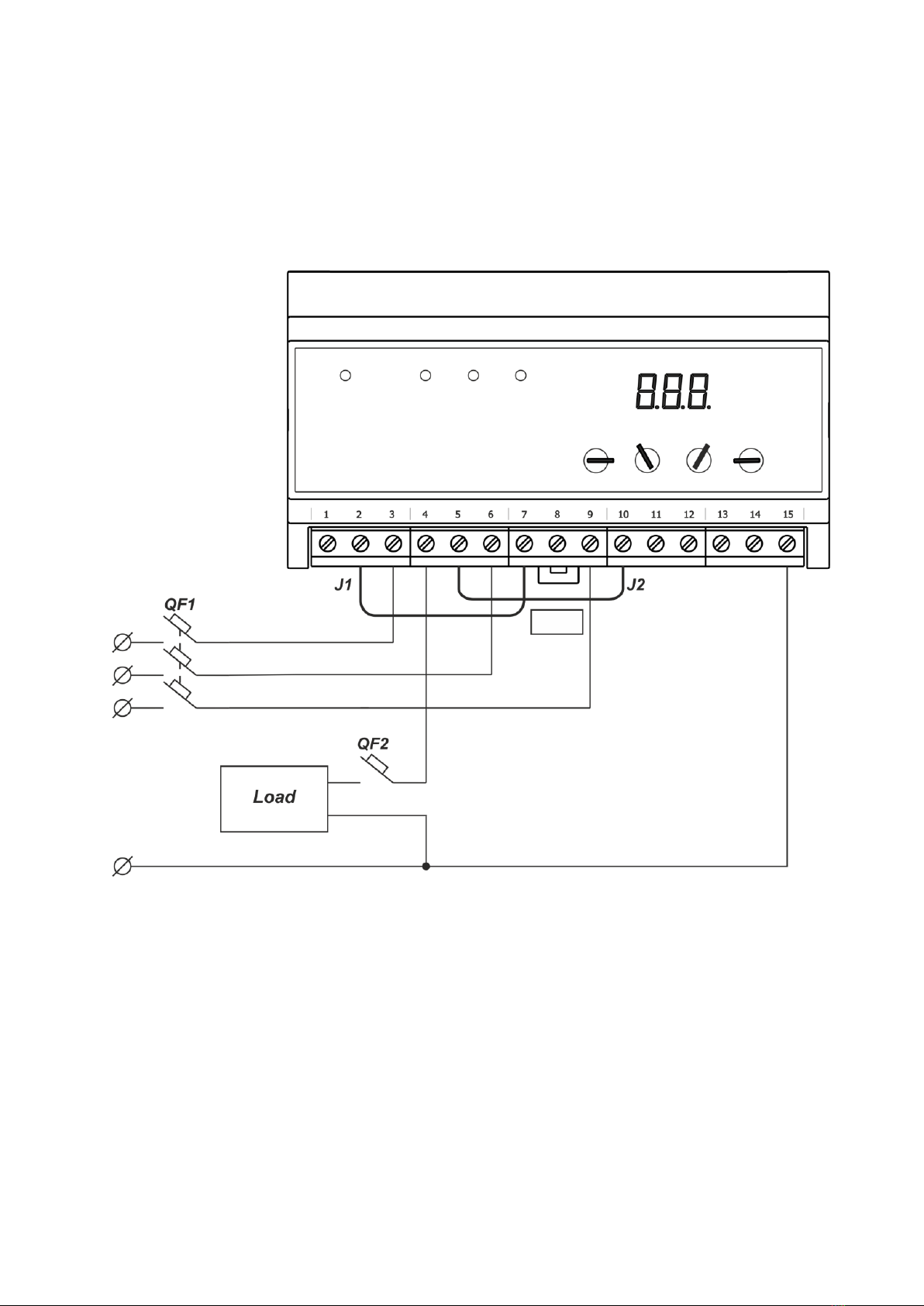
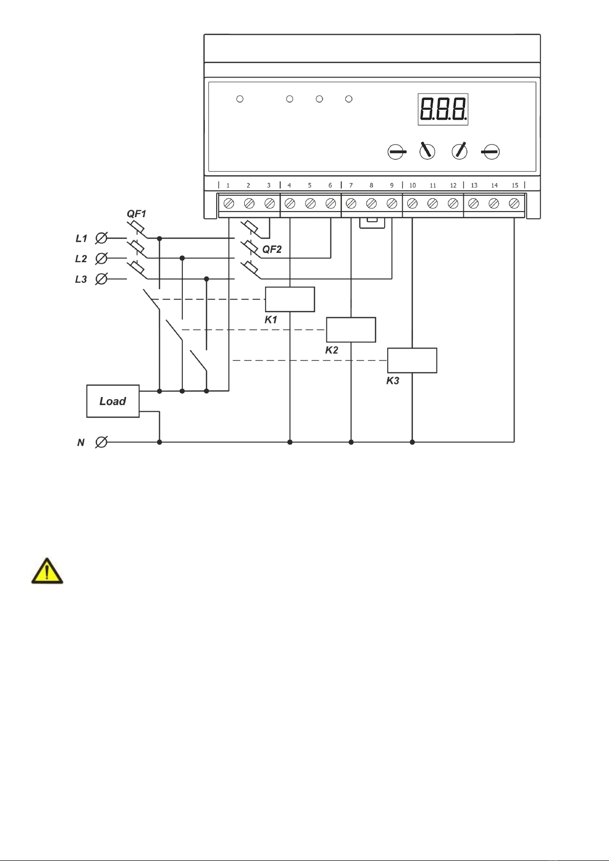
5.1.3 Make connection of PEF-319 to the three-phase line according to the figure 2 (at load value less than 30 A) or
according to the figure 3 (at load value more than 30 A with use of magnetic starters).
~ 6 ~
PEF-319
NOVATEK-ELECTRO
The limit values should be set after connecting the device to the mains with the load being disconnected:
Umin –the minimal voltage level of relay switching on;
Umax –the maximal voltage level of relay switching on;
Тon –time of automatic reset of load after restoring the voltage parameters on one of the phases, and time of
load primary switching on after energizing of the device;
Тr- time of return to the priority phase.
For the refrigerators, air conditioning devices and other compressor equipment, Тon is recommended to be set
in range of 180 –600 seconds, for other devices –according to their manuals and operating instructions.
After the setting of threshold limit values the device is ready for operation with load.
It is allowed to change the levels of Umin, Umax, Тon, Тrduring the device operation with observing the
safety rules.
J1, J2 –Power link jumpers.
QF1, QF2 –Automatic circuit breakers (the breaker nominal is selected according to the power of the connected
loading).
Figure 2 –The scheme of PEF-319 connection with load value less than 30 A
5.2 Intended use
After connection to power supply and parameters setting the PEF-319 is ready for operation.
Green light LED indicators L1, L2, L3 on the front panel show the phase to which the load is connected.
With load being connected the digital display shows the voltage of the phase which is connected to the load.
With load being disconnected the digital display shows the voltage of the phase which has the value nearest to
the set threshold voltage limits. This phase is indicated by flickering of corresponding LED indicator.
If the load is disconnected from all three phases, the red LED indicator ALARM will light on.
In case when several PEF-319 devices are used in the line, it is recommended to select different phases as a
“priority one” for different groups of consumers to avoid the phase overloading.
In case in mains several PEF-319 is used, for prevention of an overload on phases it is recommended as
priority to choose different phases for different groups of consumers.
~ 7 ~
NOVATEK-ELECTRO
PEF-319
К1, К2, К3 –magnetic starters (MS).
QF1 –Automatic breaker (the breaker nominal is selected according to the power of the connected loading).
QF2 –Automatic breaker (the breaker nominal is selected according to the power of MS).
Figure 3 –The scheme of PEF-319 connection with load value more than 30 A with use of magnetic starters
6 MAINTENANCE
6.1 Safety precautions
THE TERMINALS AND THE PRODUCT INTERNAL ELEMENTS CONTAINS POTENTIALLY LETHAL
VOLTAGE.
DURING MAINTENANCE IT IS NECESSARY TO DISABLE THE PRODUCT AND CONNECTED
DEVICES FROM THE MAINS
6.2 Maintenance of the product must be performed by qualified service personnel.
6.3 Recommended frequency of maintenance is every six months.
6.4 Maintenance procedure:
1) Check the connection reliability of the wires, if necessary, clamp with the force specified in Table 2;
2) Visually check the integrity of the housing, in case of detection of cracks and damages to remove the product
from service and send for repair;
3) If necessary, wipe with cloth the front panel and the product housing.
Do not use abrasives and solvents for cleaning.
7 OPERATION LIFE AND MANUFACTURER’S WARRANTY
7.1 The lifetime of the product is 10 years. Upon expiration of the service life, contact the manufacturer.
7.2 Shelf life is 3 years.
7.3 Warranty period of the product operation is 5 years from the date of sale.
During the warranty period of operation (in the case of failure of the product) the manufacturer is responsible for
free repair of the product.
ATTENTION! IF THE PRODUCT HAS BEEN OPERATED IN VIOLATION OF THE REQUIREMENTS OF THIS
MANUAL, THE USER WILL LOSE THE RIGHT TO WARRANTY MAINTENANCE.

~ 8 ~
PEF-319
NOVATEK-ELECTRO
7.4 Warranty service is performed at the place of purchase or by the manufacturer of the product.
7.5 Post-warranty service of the product is performed by the manufacturer at current rates.
7.6 Before sending for repair, the product should be packed in the original or other packing excluding mechanical
damage.
You are kindly requested, in case of return of the product and transfer it to the warranty (post-warranty) service,
in the field of the claims data, list the detailed reason for return.
8 TRANSPORTATION AND STORAGE
PEF-319 should be stored in the manufacturer’s packing in enclosed premises at temperature range from minus
45 to plus 60 Сand relative humidity not more than 80%, with no fumes in the air that have a deleterious effect on
the package and device material.
9 ACCEPTANCE CERTIFICATE
The universal automatic electronic phase switch PEF-319 has been manufactured and accepted according to
the requirements of effective technical documentation and is approved to be ready for operation.
Chief of quality department Date of issue
STAMP ______________ _____________
10 INFORMATION ON CLAIMS
___________________________________________________________________________________________
________________________________________________________________________________________
________________________________________________________________________________________
________________________________________________________________________________________
________________________________________________________________________________________
________________________________________________________________________________________
________________________________________________________________________________________
________________________________________________________________________________________
________________________________________________________________________________________
________________________________________________________________________________________
________________________________________________________________________________________
________________________________________________________________________________________
________________________________________________________________________________________
The Company is grateful to you for the information about the quality of the device and suggestions for its operation.
For all questions, please contact the manufacturer:
NOVATEK-ELECTRO Ltd,
59, Admiral Lazarev Str. ,
Odessa, 65007, Ukraine.
Tel.: +38 (048)738-00-28,
Tel./fax: +38 (0482) 34-36-73.
www.novatek-electro.com
Date of sale ________________ VN190402
This manual suits for next models
1
Table of contents
Other Novatek-electro Switch manuals


