- 7 -
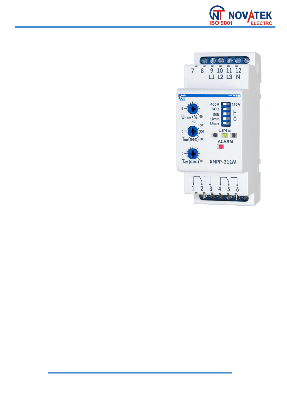
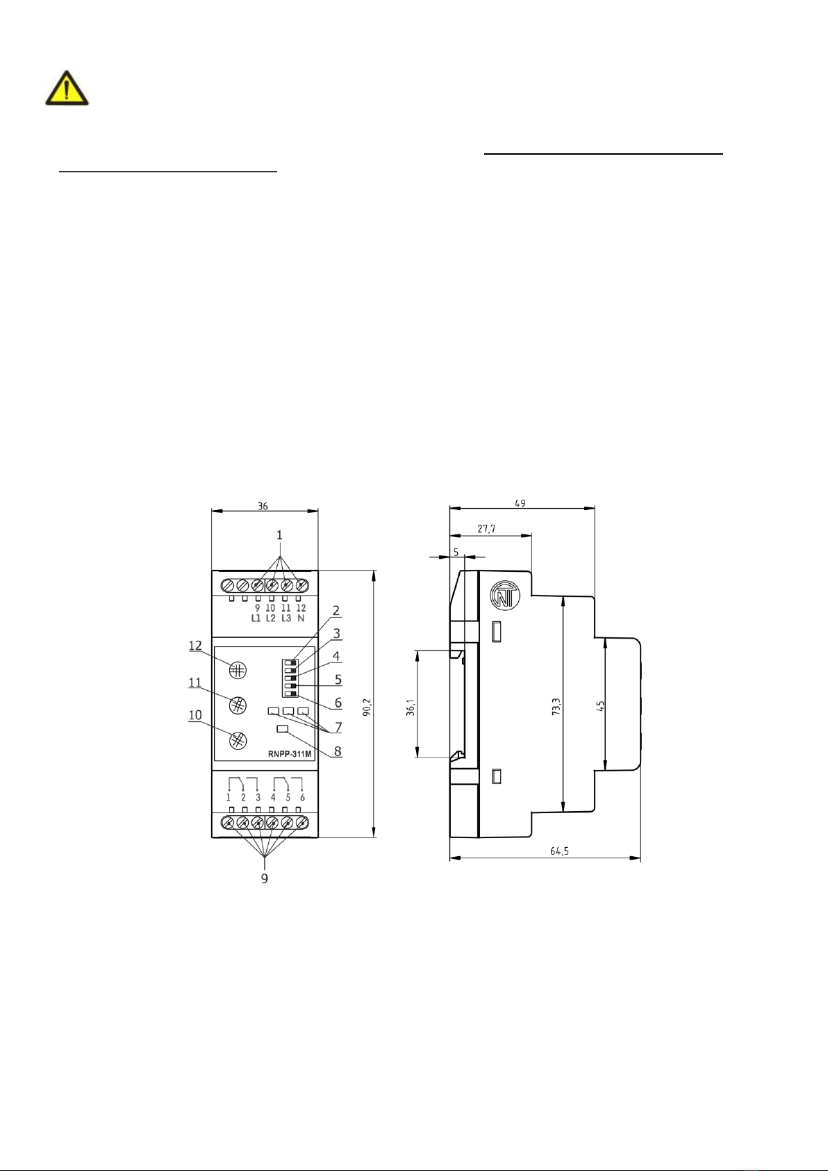
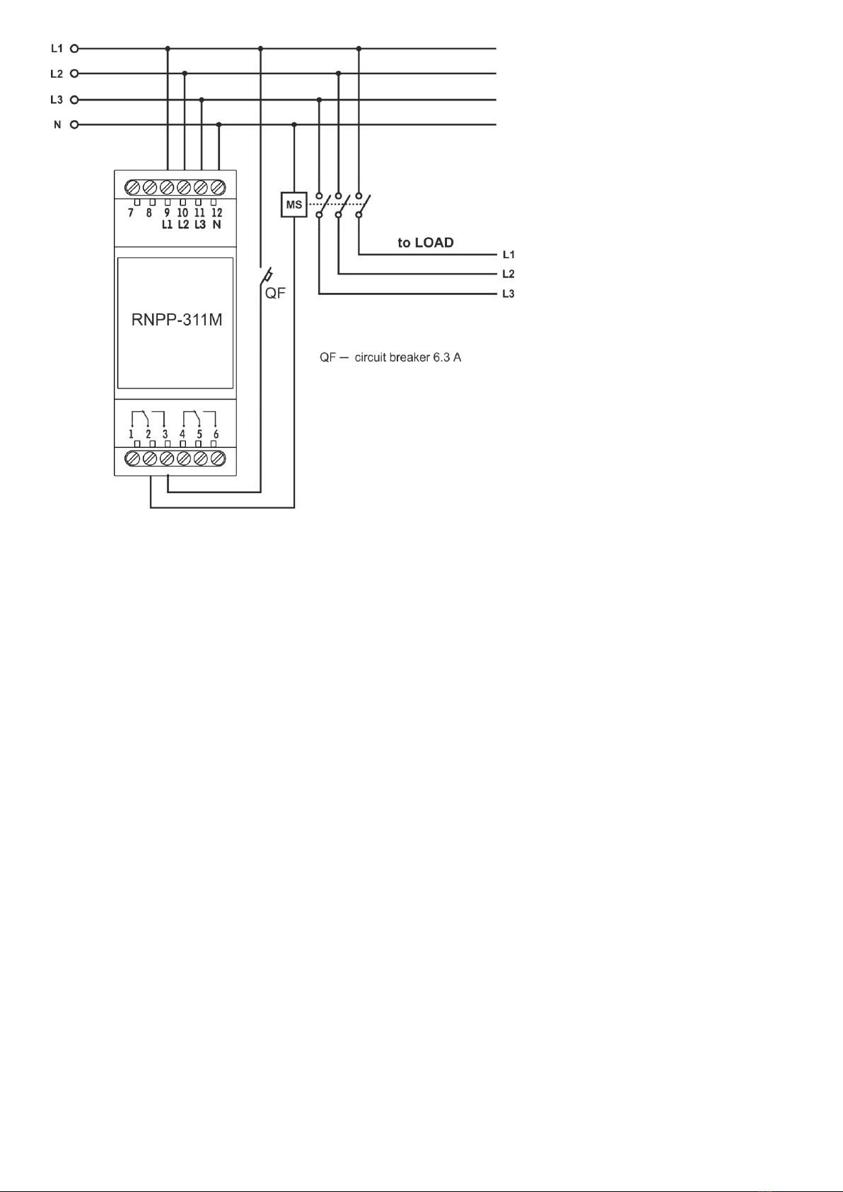
NOVATEK-ELECTRO RNPP-311M
NOTE - The failure is displayed in order of priority:
1 –Phase failure or voltage drop below 100 V (highest priority);
2 –Phase sequence;
3 –Minimum and maximum voltage;
4–Phase imbalance.
3.2.2. RNPP-311M usage examples
a) RNPP-311M in “Minimum voltage control" mode
- Switch Umin is in ON position.
- Switches Umax, IMB are in OFF position.
If the voltage drops below Umin, the device will operate after the Toff (sec) time set by the User, the red
ALARM indicator will turn ON, the corresponding LINE indicator (-s) will off. If the voltage drops below 100 V,
the device will be operated after 0.2 seconds.
b) RNPP-311M in "Minimum / maximum voltage control" and "Phases presence control" modes
- Switches Umin and Umax are in ON position.
RNPP-311M will operate if the voltage rises above the set threshold after the time Toff (sec), and when
it decreases - with the fixed delay of 12 seconds (setting the starting voltage slumps), the red ALARM
indicator will turn ON. If the phase breaks, the device will operate after 0.2 seconds.
c) Maximal voltage relay
- Switch Umax is in ON position.
- Switches Umin, SEQ, IMB are in OFF position.
- Red ALARM indicator is OFF.
If high voltage detected RNPP-311M will turn OFF the power load with time delay (Toff (sec) +0,4) sec
and the red ALARM indicator will turn ON.
d) Turn ON time delay relay
- Switches Umin, Umax are in OFF position.
The protected equipment will be connected after the AR time countdown set by the User with the help of
Ton(sec) control. In all modes of operation, the switching ON / OFF of protection due to the phase sequence
disturbance is carried out by the switch SEQ, and the switching ON / OFF due to the phase imbalance protection
- by the switch IMB. If the phase is broken or the voltage drops below 100 V in one or more phases, the device
will operate (turn OFF) the corresponding phase indicator will turn OFF.
If switches Umin, Umax,SEQ,IMB are in ON position and the voltage drop is less than Umin, the device
will operate with the fixed delay of 12 seconds (setting the starting voltage slumps).
4. MAINTENANCE
4.1. Safety precautions
THE TERMINALS AND THE PRODUCT INTERNAL ELEMENTS CONTAINS POTENTIALLY LETHAL
VOLTAGE.
DURING MAINTENANCE IT IS NECESSARY TO DISABLE THE PRODUCT AND CONNECTED
DEVICES FROM THE MAINS.
Maintenance of the unit should be performed by persons admitted to the operation and have the
appropriate permission.
The recommended frequency of maintenance is every six months.
4.2. Maintenance procedure:
1) check the wires connection reliability, if necessary –clamp with force as specified in Table 2;
2) check visually the housing integrity;
3) if necessary, wipe with cloth the front panel and the unit housing.
It is not allowed to clean the unit with abrasive materials or organic compounds (alcohol, gasoline, solvents,
etc.).
5. SERVICE LIFE AND WARRANTY
Service life –is 10 years. Contact manufacturer upon the expiry of the service life.
Guaranteed storage life –is 3 years.
Warranty period of the unit operation is 5 years from the date of sale.
During the warranty period the Manufacturer is responsible for free repair of the unit, if the Consumer has
complied with the requirements of this Operating Manual.
ATTENTION! IF THE UNIT HAS BEEN OPERATED WITH VIOLATION OF THE REQUIREMENTS OF
THIS OPERATION MANUAL, BUYER WILL FORFEIT THE RIGHT TO WARRANTY SERVICE.
Warranty service is performed at the place of purchase or by the Manufacturer of the product.