manuals.online logo
Brands
  1. Home
  2. •
  3. Brands
  4. •
  5. Veris Industries
  6. •
  7. Relay
  8. •
  9. Veris Industries Hawkeye 906 User manual

Veris Industries Hawkeye 906 User manual

CURRENT MONITORING INSTALLATION GUIDE

Z201573-0B PAGE 1 ©2006 Veris Industries USA 800.354.8556 or 503.598.4564 / support@veris.com 12061
Adjustable Current Switch Split-Core,
Self-Powered, N.C. Status Output
QUICK INSTALL
1. Plan the installation:
Locate a mounting surface for the removable mounting bracket that will allow
the monitored conductor to pass through the iris, or "window" when it is installed
and keep the product at least ½ " (13mm) from any uninsulated conductors (CE).
Determine cable routing for the controller connection, allowing wiring to reach the
mounting location.
2. Install mounting bracket
Drill holes to mount the bracket to the chosen surface using the included screws.
3. Wire the output connections between the sensor, the controller (solid-state contact),
and external power supply.
4. Snap the sensor over the wire to be monitored and clip the assembly to the
mounting bracket.
5. Calibrate the sensor (see page 2) with the load running normally.
6. Close up and power up!
Installer's Specifi cations
Amperage Range ....................... 2.5 - 135A Continuous
Output ...................................... N.C. 0.1A@30VDC, polarity sensitive
Hysteresis ..................................10% of setpoint, typical
Off -State Leakage ......................34 µA@5VDC, 200 µA@30VDC
On-state Voltage Drop (max) ....1.9VDC@0.1A
External Power .......................... 5-30VDC
Isolation .....................................600VAC rms (UL), 300VAC rms (CE)
Frequency ..................................50/60Hz.
Temperature Range ...................-15º to +60º C
Humidity Range ........................ 10-90% RH non-condensing
Safety ........................................UL 508, IEC 61010-1: 2001 CAT III
Specifi cation Note: For CE compliance, conductor shall be insulated according to
IEC 61010-1:2001, Installation Category III or equivalent.
The product design provides for basic insulation only.
Wiring Example









H906 906
DIMENSIONS










 
 
 
 
 
 
 



 
 
 
 
















H906 INSTALLATION GUIDE
Z201573-0B PAGE 2 ©2006 Veris Industries USA 800.354.8556 or 503.598.4564 / support@veris.com 12061
 










The H906 is a current-sensitive switching device which monitors current (amperage)
in the conductor passing through it. A change in amperage in the monitored
conductor which crosses the switch (setpoint) threshold plus the hysteresis value will
cause the resistance of the FET status output to change state, similar to the action of
a mechanical switch. In this model, the setpoint is adjustable through the action of a
twenty (20) turn potentiometer (see the CALIBRATION section). The status output is
suitable for connection to building controllers, or other appropriate data acquisition
equipment operating at up to 30 volts. The H906 requires a 5-30VDC external power
supply to generate its output.
OPERATION
NOTES
TROUBLESHOOTING
CALIBRATION
For load currents less than sensor minimum rating:
Wrap the monitored conductor through the center hole and around the sensor body
to produce multiple turns through the "window." This increases the current measured
by the transducer.
• Controller must be
programmed to account
for the extra turns. e.g., if
four turns pass through the
sensor (as shown) the normal
controller reading must be
divided by 4.

 

DANGER: 5A CTS CAN PRESENT HAZARDOUS VOLTAGES.
INSTALL CTS IN ACCORDANCE WITH MANUFACTURER'S
INSTRUCTIONS.
TERMINATE THE CT SECONDARY BEFORE APPLYING
CURRENT.
H6800-5A CT




> 135A (H906 max.)
For load currents greater than sensor maximum rating:
Use a 5 Amp (H681x series) Current Transformer (CT) as shown. External power supply
not shown.
Problem Solution
No Reading at Controller • Check sensor calibration (see above)
• Check for control power at sensor
(5VDC<voltage<30V)
• Check for amperage in monitored conductor (> 2.5A)
• Assure that sensor core mating surfaces are clean and
that the core clamp is completely closed
Setpoint screw has no stops The setpoint screw has a slip-clutch at both ends of its
travel to avoid damage. Twenty turns CCW will reset
the sensor to be most sensitive. Repeat calibration
above.
Both LEDs are lit Setpoint screw is too far clockwise. See solution above.
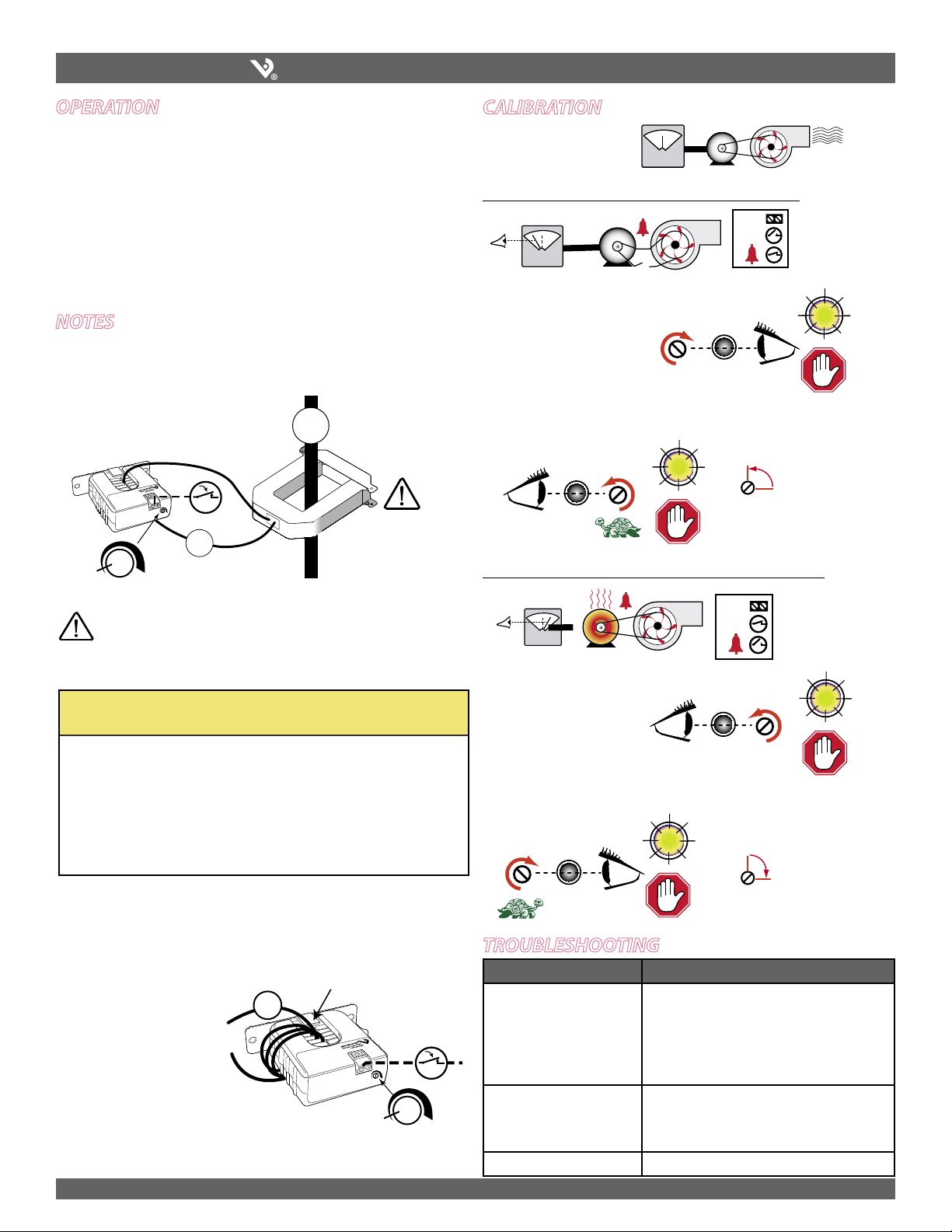
Establish Normal Load Conditions
To monitor under-current (belt loss, coupling shear, status)
OK!
�
OK!
1. Turn setpoint screw clockwise
until Status CLOSED LED
turns ON.
Turn the screw an
additional ¼ turn
counter-clockwise for
operational margin.
To monitor over-current (mechanical problems, seized impeller)
Turn the setpoint
screw an additional
¼ turn clockwise for
operational margin.
1. Turn setpoint screw
counter-clockwise until
Status OPEN LED turns ON.
2. S-l-o-w-l-y turn the setpoint screw clockwise until the Status
CLOSED LED just turns ON.
�
OK!
!
OK!

�
OK!
!
OK!



+




 



 

2. S-l-o-w-l-y turn the screw counter-clockwise until the Status OPEN LED
just turns ON.
+
 



This manual suits for next models

1

Other Veris Industries Relay manuals

Veris Industries Hawkeye 806 User manual

Veris Industries

Veris Industries Hawkeye 806 User manual

Veris Industries Hawkeye 740 User manual

Veris Industries

Veris Industries Hawkeye 740 User manual

Veris Industries Hawkeye 740 User manual

Veris Industries

Veris Industries Hawkeye 740 User manual

Veris Industries Hawkeye 735 User manual

Veris Industries

Veris Industries Hawkeye 735 User manual

Veris Industries Hawkey 739 User manual

Veris Industries

Veris Industries Hawkey 739 User manual

Veris Industries Hawkeye 809 User manual

Veris Industries

Veris Industries Hawkeye 809 User manual

Popular Relay manuals by other brands

Pilz PNOZ X9P AC/DC operating instructions

Pilz

Pilz PNOZ X9P AC/DC operating instructions

Arcteq AQ-F255 instruction manual

Arcteq

Arcteq AQ-F255 instruction manual

ABB SSR32 product manual

ABB

ABB SSR32 product manual

CD Automation REVEX 2PH 280A user manual

CD Automation

CD Automation REVEX 2PH 280A user manual

Omron ZEN Operation manual

Omron

Omron ZEN Operation manual

Pilz PNOZ 16SP operating manual

Pilz

Pilz PNOZ 16SP operating manual

C&S MRN3 manual

C&S

C&S MRN3 manual

SEB IFX4NR user manual

SEB

SEB IFX4NR user manual

Woodward MRU3-1 manual

Woodward

Woodward MRU3-1 manual

Idem SCR-73-i manual

Idem

Idem SCR-73-i manual

Advantech PCIE-1760 user manual

Advantech

Advantech PCIE-1760 user manual

ABB TF140DU installation instructions

ABB

ABB TF140DU installation instructions

Pilz PNOZ p1vp operating manual

Pilz

Pilz PNOZ p1vp operating manual

Ytc YT-310 Series product manual

Ytc

Ytc YT-310 Series product manual

Vantage Hearth WireLink EasyTouch II ScenePoint SR1 Series Installation

Vantage Hearth

Vantage Hearth WireLink EasyTouch II ScenePoint SR1 Series Installation

PPM CD30 Start guide

PPM

PPM CD30 Start guide

Broyce Control P9600 Series quick start guide

Broyce Control

Broyce Control P9600 Series quick start guide

ZIEHL STW20K operating manual

ZIEHL

ZIEHL STW20K operating manual

manuals.online logo
manuals.online logoBrands
  • About & Mission
  • Contact us
  • Privacy Policy
  • Terms and Conditions

Copyright 2025 Manuals.Online. All Rights Reserved.