VAMP VAMP 55 Quick guide

VAMP 55
Voltage and frequency protection relay
Operation and configuration
instructions
Technical description

VM55.EN005

Operation and configuration
Table of Contents
VM55.EN005
VAMP 24h support phone +358 (0)20 753 3264
3
Table of Contents
1. General ...................................................................................4
1.1. Relay features.....................................................................4
1.2. User interface......................................................................5
1.3. Operating Safety................................................................5
2. Local panel user interface ....................................................6
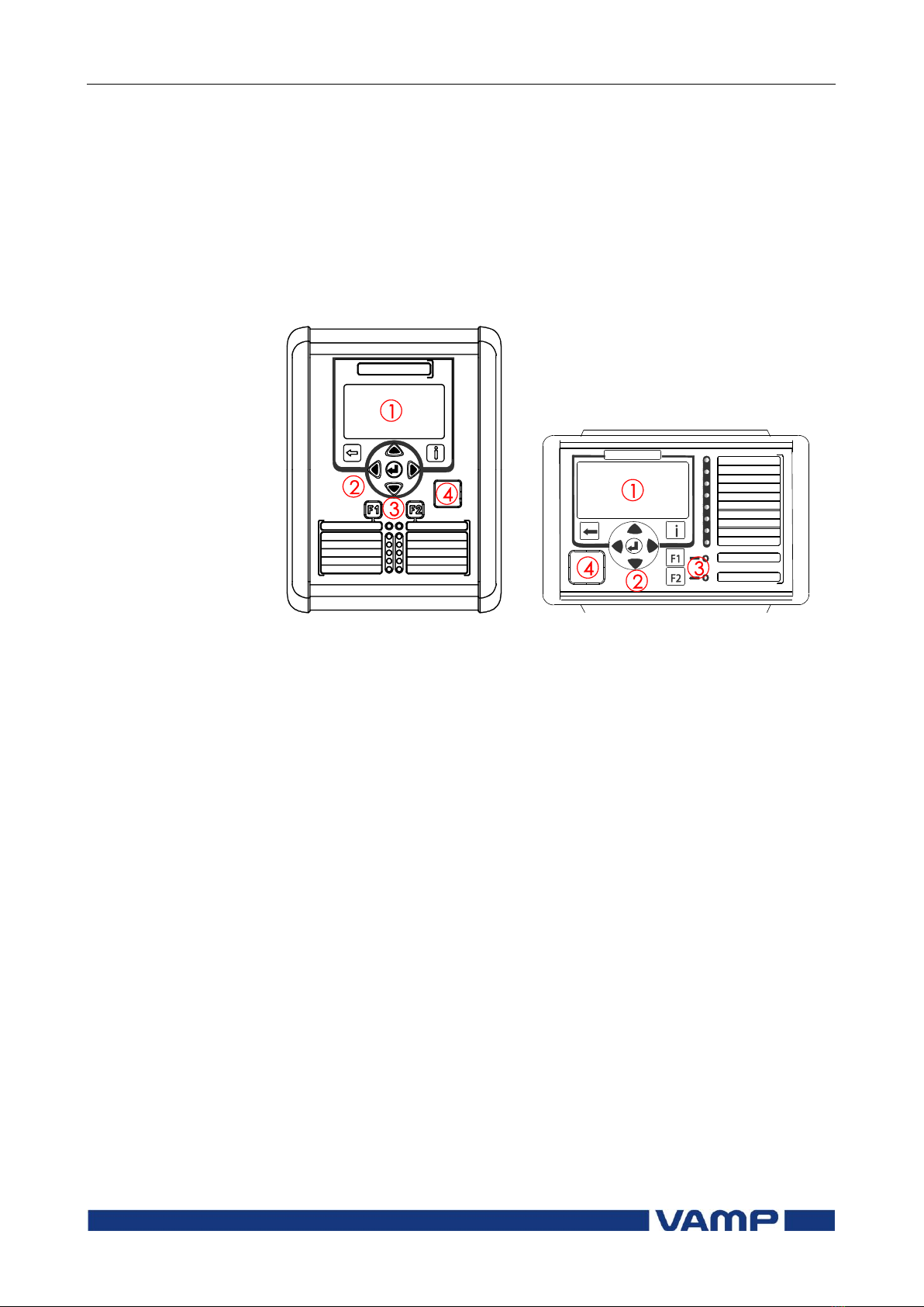
2.1. Relay front panel................................................................6
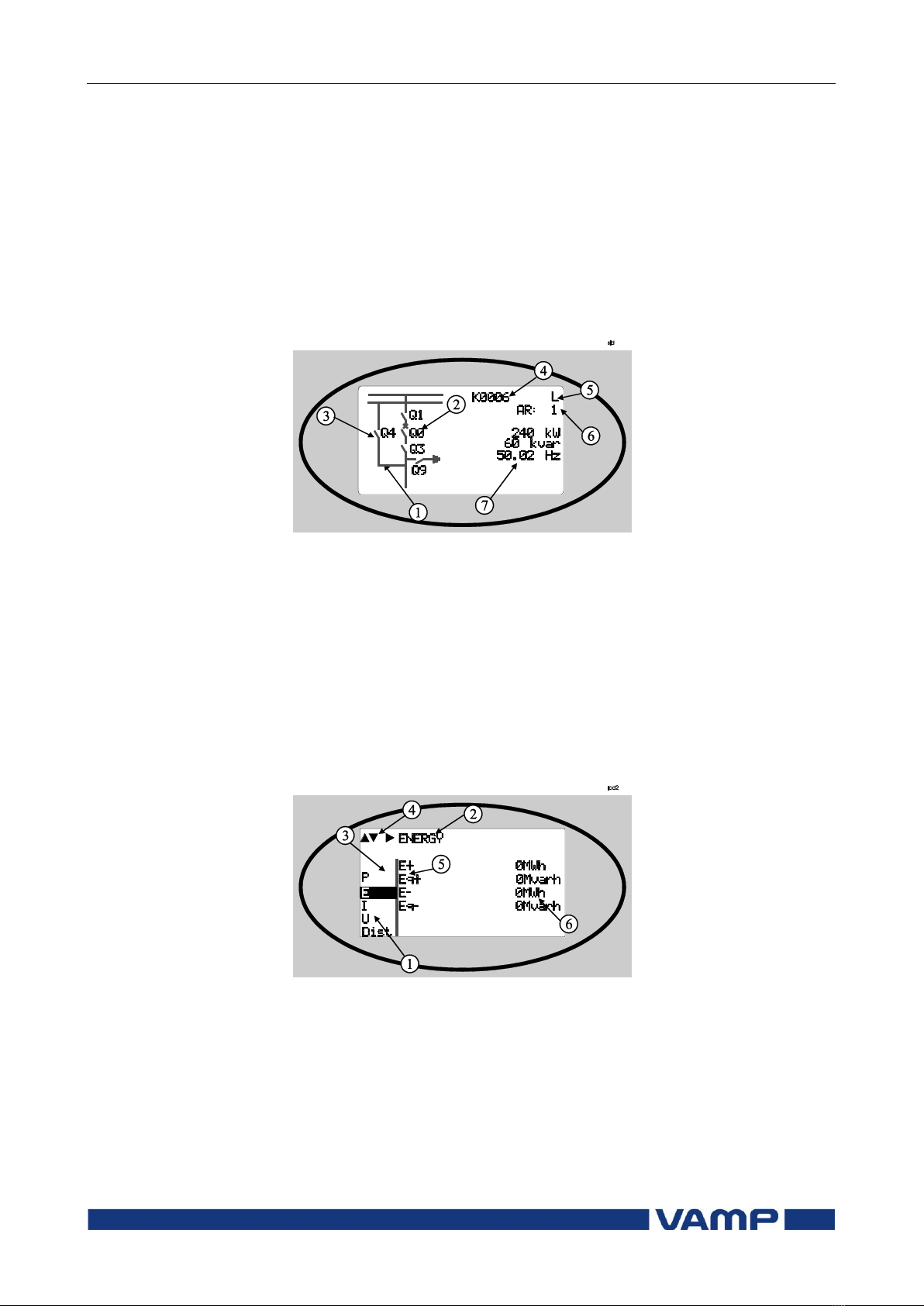
2.1.1. Display .........................................................................7
2.1.2. Menu navigation and pointers................................8
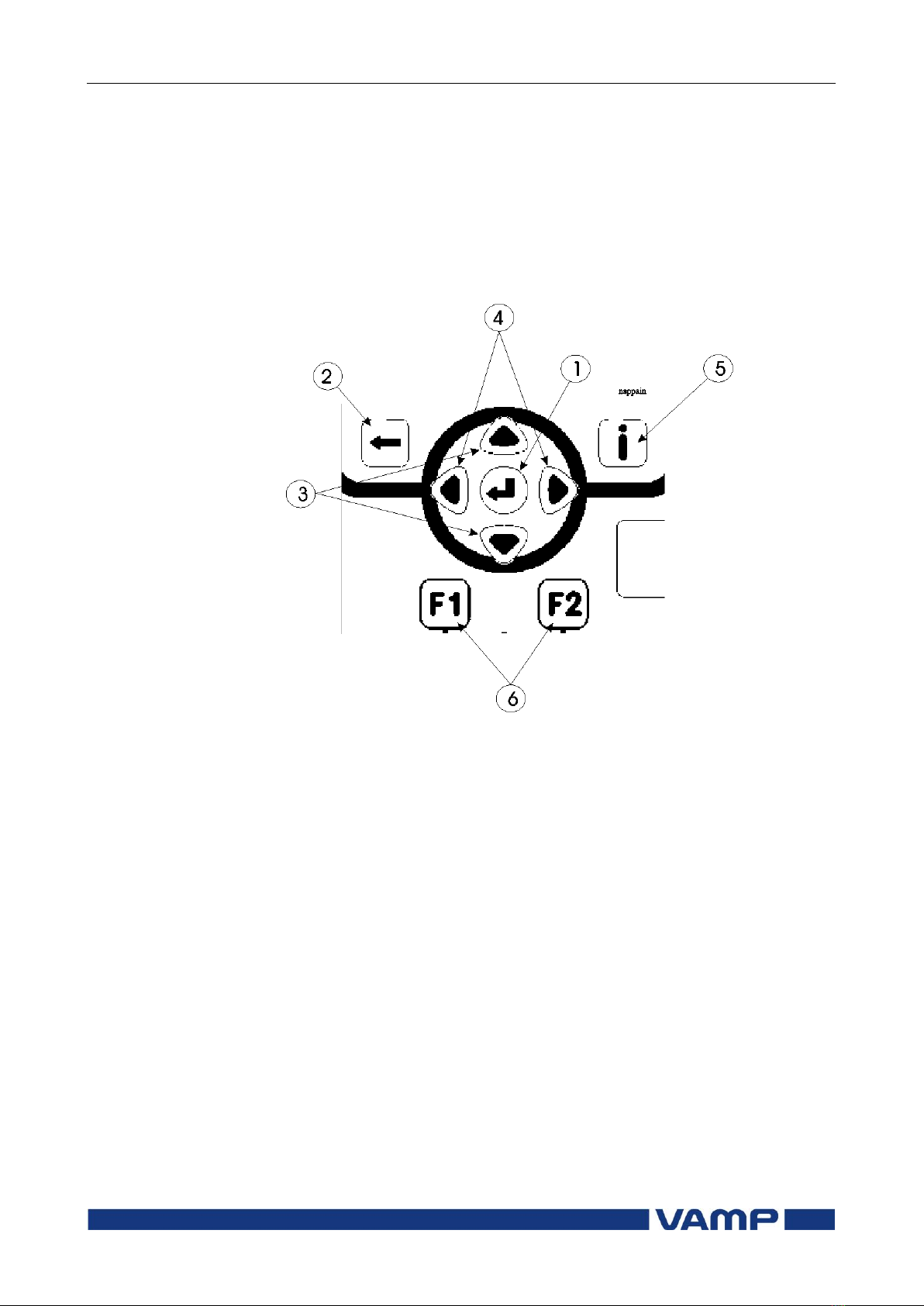
2.1.3. Keypad........................................................................9
2.1.4. Operation indicators .............................................. 10
2.1.5. Adjusting display contrast ..................................... 11
2.2. Local panel operations .................................................. 11
2.2.1. Navigating in menus .............................................. 11
2.2.2. Menu structure of protection functions .............. 14
2.2.3. Setting groups ......................................................... 18
2.2.4. Fault logs .................................................................. 19
2.2.5. Operating levels...................................................... 20
2.3. Operating measures....................................................... 22
2.3.1. Control functions .................................................... 22
2.3.2. Measured data ....................................................... 23
2.3.3. Reading event register .......................................... 24
2.3.4. Forced control (Force)........................................... 25
2.4. Configuration and parameter setting ......................... 26
2.4.1. Parameter setting ................................................... 27
2.4.2. Setting range limits ................................................. 28
2.4.3. Disturbance recorder menu DR ........................... 28
2.4.4. Configuring digital inputs DI.................................. 29
2.4.5. Configuring digital outputs DO ............................ 29
2.4.6. Configuring analogue outputs AO (Option)...... 30
2.4.7. Protection menu Prot ............................................. 30
2.4.8. Configuration menu CONF ................................... 31
2.4.9. Protocol menu Bus.................................................. 32
2.4.10.Single line diagram editing ................................... 35
2.4.11.Blocking and interlocking configuration............. 35
3. VAMPSET PC software ..........................................................36

1.1 Relay features
1 General
Operation and configuration
4
VAMP 24h support phone +358 (0)20 753 3264
VM55.EN005
1. General
This first part (Operation and configuration) of the publication
contains general descriptions of the functions, of the protection
relay as well as operation instructions. It also includes
instructions for parameterization and configuration of the relay
and instructions for changing settings.
The second part (Technical description) of the publication
includes detailed protection function descriptions as well as
application examples and technical data sheets.
The Mounting and Commissioning Instructions are published
in a separate publication with the code VMMC.EN0xx.
1.1. Relay features
The VAMP 55 protection relay concept has two alternative
casing layout designs: basic and slim fit.
The VAMP 55S includes more compact casing than in the basic
design. In the VAMP 55S, the same protection, measurement
and control functions and communication interfaces are
supported as in the basic 55 relays.
The comprehensive protection functions of the relay make it
ideal for utility, industrial, marine and off-shore power
distribution applications. The relay features the following
protection functions.
List of protection functions
IEEE/ANSI
code
IEC symbol
Function name
59
U>, U>>,
U>>>
Overvoltage protection
24
U/f>
Volts/hertz over excitation
protection
27P
U1<, U1<<
Positive sequence undervoltage
protection for generator
applications
27
U<, U<<,
U<<<
Undervoltage protection
59N
U0>, U0>>
Zero sequence voltage protection
81H/81L
f><, f>><<
Overfrequency and underfrequency
protection
81L
f<, f<<
Underfrequency protection
25
∆f, ∆U, ∆φ
Synchrocheck

Operation and configuration
1 General
1.2 User interface
VM55.EN005
VAMP 24h support phone +358 (0)20 753 3264
5
IEEE/ANSI
code
IEC symbol
Function name
50BF
CBFP
Circuit-breaker failure protection
99
Prg1…8
Programmable stages
Further the relay includes a disturbance recorder.
The relay communicates with other systems using common
protocols, such as the Modbus RTU, ModbusTCP, Profibus DP,
IEC 60870-5-103, IEC 60870-5-101, IEC 61850, SPA bus, and
DNP 3.0. An optional communication option is required for
this (see ordering code in technical description).
1.2. User interface
The relay can be controlled in three ways:
Locally with the push-buttons on the relay front panel
Locally using a PC connected to the USB port on the front
Via remote control over the optional remote control port on
the relay rear panel.
1.3. Operating Safety
The terminals on the rear panel of the relay may
carry dangerous voltages, even if the auxiliary
voltage is switched off. A live current transformer
secondary circuit must not be opened.
Disconnecting a live circuit may cause dangerous
voltages! Any operational measures must be carried out
according to national and local handling directives and
instructions.
Carefully read through all operation instructions before any
operational measures are carried out.

2.1 Relay front panel
2 Local panel user interface
Operation and configuration
6
VAMP 24h support phone +358 (0)20 753 3264
VM55.EN005
2. Local panel user interface
2.1. Relay front panel
The figure below shows, as an example, the front panel of the
voltage and frequency protection relay VAMP 55 and the
location of the user interface elements used for local control.
Figure 2.1-1. Relay front panel
1. LCD dot matrix display
2. Keypad
3. LED indicators
4. USB communication port for PC

Operation and configuration
2 Local panel user interface
2.1 Relay front panel
VM55.EN005
VAMP 24h support phone +358 (0)20 753 3264
7
2.1.1. Display
The relay is provided with a backlighted 128x64 LCD dot
matrix display. The display enables showing 21 characters is
one row and eight rows at the same time. The display has two
different purposes: one is to show the single line diagram of the
relay with the object status, measurement values, identification
etc. (Figure 2.1.1-1). The other purpose is to show the
configuration and parameterization values of the relay (Figure
2.1.1-2).
Figure 2.1.1-1 Sections of the LCD dot matrix display
1. Freely configurable single-line diagram
2. Controllable objects (max six objects)
3. Object statuses (max eight objects)
4. Bay identification
5. Local/Remote selection
6. Auto-reclose on/off selection (if applicable)
7. Freely selectable measurement values (max. six values)
Figure 2.1.1-2 Sections of the LCD dot matrix display
1. Main menu column
2. The heading of the active menu
3. The cursor of the main menu
4. Possible navigating directions (push buttons)
5. Measured/setting parameter
6. Measured/set value

2.1 Relay front panel
2 Local panel user interface
Operation and configuration
8
VAMP 24h support phone +358 (0)20 753 3264
VM55.EN005
Backlight control
Display backlight can be switched on with a digital input,
virtual input or virtual output. LOCALPANEL CONF/Display
backlight ctrl setting is used for selecting trigger input for
backlight control. When the selected input activates (rising
edge), display backlight is set on for 60 minutes.
2.1.2. Menu navigation and pointers
1. Use the arrow keys UP and DOWN to move up and down in
the main menu, that is, on the left-hand side of the display.
The active main menu option is indicated with a cursor. The
options in the main menu items are abbreviations, e.g. Evnt
= events.
2. After any selection, the arrow symbols in the upper left
corner of the display show the possible navigating directions
(applicable navigation keys) in the menu.
3. The name of the active submenu and a possible ANSI code
of the selected function are shown in the upper part of the
display, e.g. LINE VOLTAGES.
4. Further, each display holds the measured values and units
of one or more quantities or parameters, e.g. U12max 23000
V.

Operation and configuration
2 Local panel user interface
2.1 Relay front panel
VM55.EN005
VAMP 24h support phone +358 (0)20 753 3264
9
2.1.3. Keypad
You can navigate in the menu and set the required parameter
values using the keypad and the guidance given in the display.
Furthermore, the keypad is used to control objects and switches
on the single line diagram display. The keypad is composed of
four arrow keys, one cancel key, one enter key, one info key and
two configurable function keys.
Figure 2.1.3-1 Keys on the keypad
1. Enter and confirmation key (ENTER)
2. Cancel key (CANCEL)
3. Up/Down [Increase/Decrease] arrow keys (UP/DOWN)
4. Keys for selecting submenus [selecting a digit in a
numerical value] (LEFT/RIGHT)
5. Additional information key (INFO)
6. Function keys 1 and 2 (F1 / F2)
As default F1 toggles Virtual Input 1 (VI1) On/Off
As default F2 toggles Virtual Input 2 (VI2) On/Off
Instructions about programming F1 / F2, see chapter 5.4
Function keys / F1 & F2 in the technical description.
NOTE! The term, which is used for the buttons in this manual, is inside the
brackets.

2.1 Relay front panel
2 Local panel user interface
Operation and configuration
10
VAMP 24h support phone +358 (0)20 753 3264
VM55.EN005
2.1.4. Operation indicators
The relay is provided with twelve LED indicators:
Figure 2.1.4-1. Operation indicators of the relay
LED indicator
Meaning
Measure/ Remarks
Power LED lit
The auxiliary power has
been switched on
Normal operation state
Error LED lit
Internal fault, operates in
parallel with the self
supervision output relay
The relay attempts to
reboot [REBOOT]. If the
error LED remains lit,
call for maintenance.
A- H LED lit
Application-related status
indicators.
Configurable
F1 / F2 LED lit
Corresponding function
key pressed / activated
Depending of function
programmed to F1 / F2
Resetting latched indicators and output relays
All the indicators and output relays can be given a latching
function in the configuration.
There are several ways to reset latched indicators and relays:
From the alarm list, move back to the initial display by
pushing the CANCEL key for approx. 3s. Then reset the
latched indicators and output relays by pushing the ENTER
key.
Acknowledge each event in the alarm list one by one by
pushing the ENTER key equivalent times. Then, in the
initial display, reset the latched indicators and output
relays by pushing the ENTER key.
The latched indicators and relays can also be reset via a remote
communication bus or via a digital input configured for that
purpose.

Operation and configuration
2 Local panel user interface
2.2 Local panel operations
VM55.EN005
VAMP 24h support phone +358 (0)20 753 3264
11
Renaming LEDs
In VAMPSET software under the menu ”LED NAMES” it is
possible to assign custom name for each configurable LED.
2.1.5. Adjusting display contrast
The readability of the LCD varies with the brightness and the
temperature of the environment. The contrast of the display
can be adjusted via the PC user interface, see chapter 3.
2.2. Local panel operations
The front panel can be used to control objects, change the local/
remote status, read the measured values, set parameters, and
to configure relay functions. Some parameters, however, can
only be set by means of a PC connected to the local
communication port. Some parameters are factory-set.
2.2.1. Navigating in menus
All the menu functions are based on the main menu/submenu
structure:
1. Use the arrow keys UP and DOWN to move up and down in
the main menu.
2. To move to a submenu, repeatedly push the RIGHT key
until the required submenu is shown. Correspondingly,
push the LEFT key to return to the main menu.
3. Push the ENTER key to confirm the selected submenu. If
there are more than six items in the selected submenu, a
black line appears to the right side of the display (Figure
2.2.1-1). It is then possible to scroll down in the submenu.
Figure 2.2.1-1 Example of scroll indication
4. Push the CANCEL key to cancel a selection.
5. Hold the CANCEL key pushed for appr. 4 sec. to display the
title screen.
6. Pushing the UP or DOWN key in any position of a
submenu, when it is not selected, brings you directly one
step up or down in the main menu.

2.2 Local panel operations
2 Local panel user interface
Operation and configuration
12
VAMP 24h support phone +358 (0)20 753 3264
VM55.EN005
The active main menu selection is indicated with black
background color. The possible navigating directions in the
menu are shown in the upper-left corner by means of black
triangular symbols.
Figure 2.2.1-2 Principles of the menu structure and navigation in the menus
7. Push the INFO key and then the ENTER key to give the
password.
8. Push the INFO key to obtain additional information about
any menu item.
9. Push the CANCEL key to revert to the normal display.

Operation and configuration
2 Local panel user interface
2.2 Local panel operations
VM55.EN005
VAMP 24h support phone +358 (0)20 753 3264
13
Main menu
The general menu structure is shown in Figure 2.2.1-2. The
menu is dependent on the user’s configuration and the options
according the order code. For example only the enabled
protection stages will appear in the menu.
A list of the local main menu
Main
menu
Number
of
menus
Description
ANSI
code
Note
1
Interactive mimic display
1
5
Double size measurements
defined by the user
1
1
Title screen with device name,
time and firmware version.
U
19
Voltage measurements
Umax
9
Time stamped min & max of
voltages
Evnt
2
Events
DR
3
Disturbance recorder
2
Runh
2
Running hour counter. Active
time of a selected digital input
and time stamps of the latest
start and stop.
TIMR
6
Day and week timers
DI
5
Digital inputs including virtual
inputs
DO
4
Digital outputs (relays) and
output matrix
ExtAI
External analogue inputs
3
ExDI
External digital inputs
3
ExDO
External digital outputs
3
Prot
18
Protection counters, combined
overcurrent status, protection
status, protection enabling, and
block matrix
U>
4
1st overvoltage stage
59
4
U>>
3
2nd overvoltage stage
59
4
U>>>
3
3rd overvoltage stage
59
4
Uf>
3
Overexcitation stage volt/hertz
24
4
U1<
4
1st positive sequence
undervoltage stage
27P
4
U1<<
4
2nd positive sequence
undervoltage stage
27P
4
U<
4
1st undervoltage stage
27
4
U<<
3
2nd undervoltage stage
27
4
U<<<
3
3rd undervoltage stage
27
4
Uo>
3
1st residual overvoltage stage
59N
4
Uo>>
3
2nd residual overvoltage stage
59N
4

2.2 Local panel operations
2 Local panel user interface
Operation and configuration
14
VAMP 24h support phone +358 (0)20 753 3264
VM55.EN005
Main
menu
Number
of
menus
Description
ANSI
code
Note
f><
4
1st over/under-frequency stage
81
4
f>><<
4
2nd over/under-frequency stage
81
4
f<
4
1st underfrequency stage
81L
4
f<<
4
2nd underfrequency stage
81L
4
Prg1
3
1st programmable stage
99
4
Prg2
3
2nd programmable stage
99
4
Prg3
3
3rd programmable stage
99
4
Prg4
3
4th programmable stage
99
4
Prg5
3
5th programmable stage
99
4
Prg6
3
6th programmable stage
99
4
Prg7
3
7th programmable stage
99
4
Prg8
3
8th programmable stage
99
4
SyC1
5
Synchrocheck 1
25
CBFP
3
Circuit breaker failure
protection
50BF
4
AR
15
Auto-reclose
79
OBJ
11
Object definitions
5
Lgic
2
Status and counters of user's
logic
1
CONF
9
Device setup, scaling etc.
6
Bus
18
Serial port and protocol
configuration
7
Opt
1
Option cards
Diag
9
Device selfdiagnosis
Notes
1
Configuration is done with VAMPSET
2
Recording files are read with VAMPSET
3
The menu is visible only if protocol "ExternalIO" is selected for one of
the serial ports. Serial ports are configured in menu "Bus".
4
The menu is visible only if the stage is enabled.
5
Objects are circuit breakers, disconnectors etc.
6
There are two extra menus, which are visible only if the access level
"operator" or "configurator" has been opened with the corresponding
password.
7
Detailed protocol configuration is done with VAMPSET.
2.2.2. Menu structure of protection functions
The general structure of all protection function menus is
similar although the details do differ from stage to stage. As an
example the details of the second overvoltage stage U>> menus
are shown below.

Operation and configuration
2 Local panel user interface
2.2 Local panel operations
VM55.EN005
VAMP 24h support phone +358 (0)20 753 3264
15
First menu of U>> 59 stage
Figure 2.2.2-1 First menu of U>> 59 stage
This is the status, start and trip counter and setting group
menu. The content is:
Status –
The stage is not detecting any fault at the moment. The
stage can also be forced to pick-up or trip is the operating
level is “Configurator” and the force flag below is on.
Operating levels are explained in chapter 2.2.5
SCntr 5
The stage has picked-up a fault five times since the last
reset or restart. This value can be cleared if the operating
level is at least “Operator”.
TCntr 2
The stage has tripped two times since the last reset or
restart. This value can be cleared if the operating level is at
least “Operator”.
SetGrp 1
The active setting group is one. This value can be edited if
the operating level is at least “Operator”. Setting groups are
explained in chapter 2.2.3.
SGrpDI –
The setting group is not controlled by any digital input. This
value can be edited if the operating level is at least
“Configurator”.
Force Off
The status forcing and output relay forcing is disabled. This
force flag status can be set to “On” or back to “Off” if the
operating level is at least “Configurator”. If no front panel
button is pressed within five minutes and there is no
VAMPSET communication, the force flag will be set to “Off”
position. The forcing is explained in Chapter 2.3.4.

2.2 Local panel operations
2 Local panel user interface
Operation and configuration
16
VAMP 24h support phone +358 (0)20 753 3264
VM55.EN005
Second menu of U>> 59 stage
Figure 2.2.2-2 Second menu(next on the right) of U> 59 stage
This is the main setting menu. The content is:
Stage setting group 1
These are the group 1 setting values. The other setting
group can be seen by pressing push buttons ENTER and
then RIGHT or LEFT. Setting groups are explained in
chapter 2.2.3.
ILmax 0V
The maximum of three measured voltages is at the moment
0V. This is the value the stage is supervising.
Status –
Status of the stage. This is just a copy of the status value in
the first menu.
U>> 13000 V
The pick-up limit is 13000 V in primary value.
U>> 130%Un
The pick-up limit is 1,3 times the rated voltage. This value
can be edited if the operating level is at least “Operator”.
Operating levels are explained in chapter 2.2.5.
t>> 0.10s
The total operation delay is set to 100 ms. This value can be
edited if the operating level is at least “Operator”.

Operation and configuration
2 Local panel user interface
2.2 Local panel operations
VM55.EN005
VAMP 24h support phone +358 (0)20 753 3264
17
Third menu of U>> 59 stage
Figure 2.2.2-3 Third and last menu (next on the right) of U>> 59 stage
This is the menu for registered values by the U>> stage. Fault
logs are explained in chapter 2.2.4.
FAULT LOG 1
This is the latest of the eight available logs. You may move
between the logs by pressing push buttons ENTER and then
RIGHT or LEFT.
2009 –01 –07
Date of the log.
01:45:17.577
Time of the log.
Type U12,U31
The overvoltage fault has been detected in phases L12 and
L31
Flt 131.4 %Un
The fault voltage has been 131.4 % of the nominal value.
PreFlt 38.1 %Un
Prefault voltage has been 38.1 % of the nominal value.
EDly 100%
The elapsed operation delay has been 100% of the setting
0.10 s. Any registered elapsed delay less than 100 % means
that the stage has not tripped, because the fault duration
has been shorter that the delay setting.
SetGrp 1
The setting group has been 1. This line can be reached by
pressing ENTER and several times the DOWN button.

2.2 Local panel operations
2 Local panel user interface
Operation and configuration
18
VAMP 24h support phone +358 (0)20 753 3264
VM55.EN005
2.2.3. Setting groups
Most of the protection functions of the relay have two setting
groups. These groups are useful for example when the network
topology is changed frequently. The active group can be
changed by a digital input, through remote communication or
locally by using the local panel.
The active setting group of each protection function can be
selected separately. Figure 2.2.3-1 shows an example where the
changing of the U>> setting group is handled with digital input
one (SGrpDI). If the digital input is TRUE, the active setting
group is group two and correspondingly, the active group is
group one, if the digital input is FALSE. If no digital input is
selected (SGrpDI = -), the active group can be selected by
changing the value of the parameter SetGrp.
Figure 2.2.3-1 Example of protection submenu with setting group
parameters
The changing of the setting parameters can be done easily.
When the desired submenu has been found (with the arrow
keys), press the ENTER key to select the submenu. Now the
selected setting group is indicated in the down-left corner of the
display (See Figure 2.2.3.-2). Set1 is setting group one and Set2
is setting group two. When the needed changes, to the selected
setting group, have been done, press the LEFT or the RIGHT
key to select another group (the LEFT key is used when the
active setting group is 2 and the RIGHT key is used when the
active setting group is 1).
Figure 2.2.3-2 Example of U>> setting submenu

Operation and configuration
2 Local panel user interface
2.2 Local panel operations
VM55.EN005
VAMP 24h support phone +358 (0)20 753 3264
19
2.2.4. Fault logs
All the protection functions include fault logs. The fault log of a
function can register up to eight different faults with time
stamp information, fault values etc. The fault logs are stored in
non-volatile memory. Each function has its own logs. The fault
logs are not cleared when power is switched off. The user is
able to clear all logs using VAMPSET. Each function has its
own logs (See Figure 2.2.4-1).
Figure 2.2.4-1 Example of fault log
To see the values of, for example, log two, press then ENTER
key to select the current log (log one). The current log number
is then indicated in the down-left corner of the display (See
Figure 2.2.4-2, Log2 = log two). The log two is selected by
pressing the RIGHT key once.
Figure 2.2.4-2 Example of selected fault log

2.2 Local panel operations
2 Local panel user interface
Operation and configuration
20
VAMP 24h support phone +358 (0)20 753 3264
VM55.EN005
2.2.5. Operating levels
The relay has three operating levels: User level, Operator level
and Configurator level. The purpose of the access levels is to
prevent accidental change of relay configurations, parameters
or settings.
USER level
Use:
Possible to read e.g. parameter values,
measurements and events
Opening:
Level permanently open
Closing:
Closing not possible
OPERATOR level
Use:
Possible to control objects and to change e.g.
the settings of the protection stages
Opening:
Default password is 1
Setting state:
Push ENTER
Closing:
The level is automatically closed after 10
minutes idle time. Giving the password 9999
can also close the level.
CONFIGURATOR level
Use:
The configurator level is needed during the
commissioning of the relay. E.g. the scaling of
the voltage and current transformers can be
set.
Opening:
Default password is 2
Setting state:
Push ENTER
Closing:
The level is automatically closed after 10
minutes idle time. Giving the password 9999
can also close the level.
Table of contents
Other VAMP Relay manuals