NOVAWINCH FENIX 25 Operation and maintenance manual

1689 Xianyuan Road,Jinhua,Zhejiang,China
Tel:0086-579-82262697
Fax:0086-579-82262706
E-mail: info@nowvow.net
http://www.novawinch.com
PLEASE READ CAREFULLY BEFORE OPERATE THE WINCH
2020.11.18
ELECTRIC WINCH
FENIX 25
FENIX 35
FENIX 45

SAFETY PRECAUTIONS
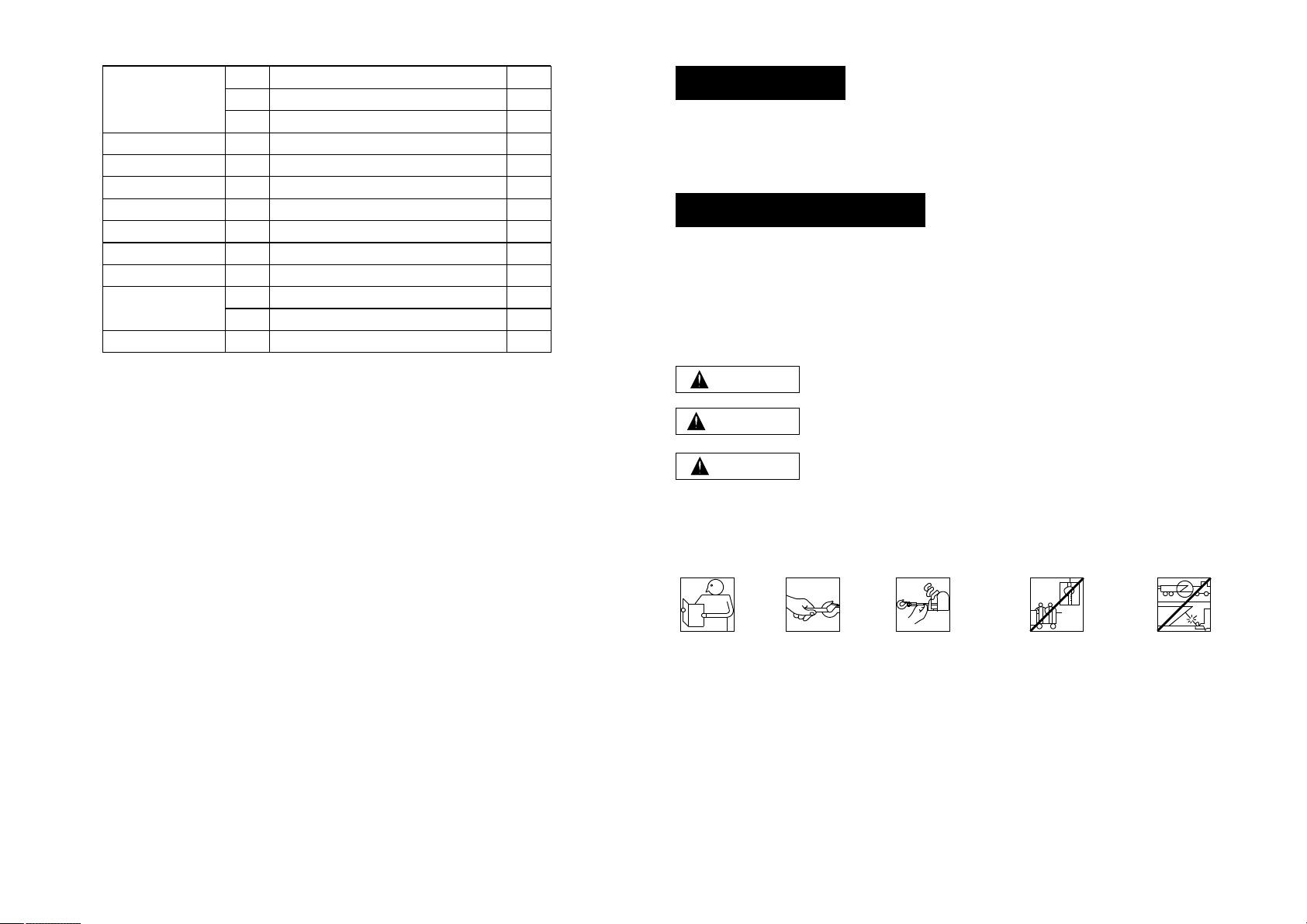
Always Use
Handsaver
Keep clear of winch,
wire rope and hook
while operating
Read Owner's
Manual
Never Use winch
to lift or move
people
Never Use
winch to hold
loads in place
The responsibility for safe installation and operation of this winch ultimately rests with
you, the operator . Read and understand all safety precautions and operating instruc-
tion before installing and operating the winch. Careless winch operating can result in
serous injury and/or property damage. Never obscure or remove the warning or
instruction labels.
Throughout this manual, you will find notations with the following headings:
Indicates an imminently hazardous situation which, if not
avoided, will result in death or serious injury.
Indicates a potentially hazardous situation which, if not avoided,
could result in death or serious injury.
Indicates a potentially hazardous situation which, if not avoided,
may result in minor or moderate injury. This notation is also used
to alert against unsafe practices.
Note: Indicates additional information in the installation and operation procedures
of your winch
The following symbols on the product and in the Owners manual are used:
Correct installation your winch is a requirement for proper operation.
WARNING
CAUTION
DANGER
INTRODUCTION
Thank you for purchasing from Novawinch.It is designed and manufacture to provid
years of trouble-free operation.We hope you are pleased with it is performance
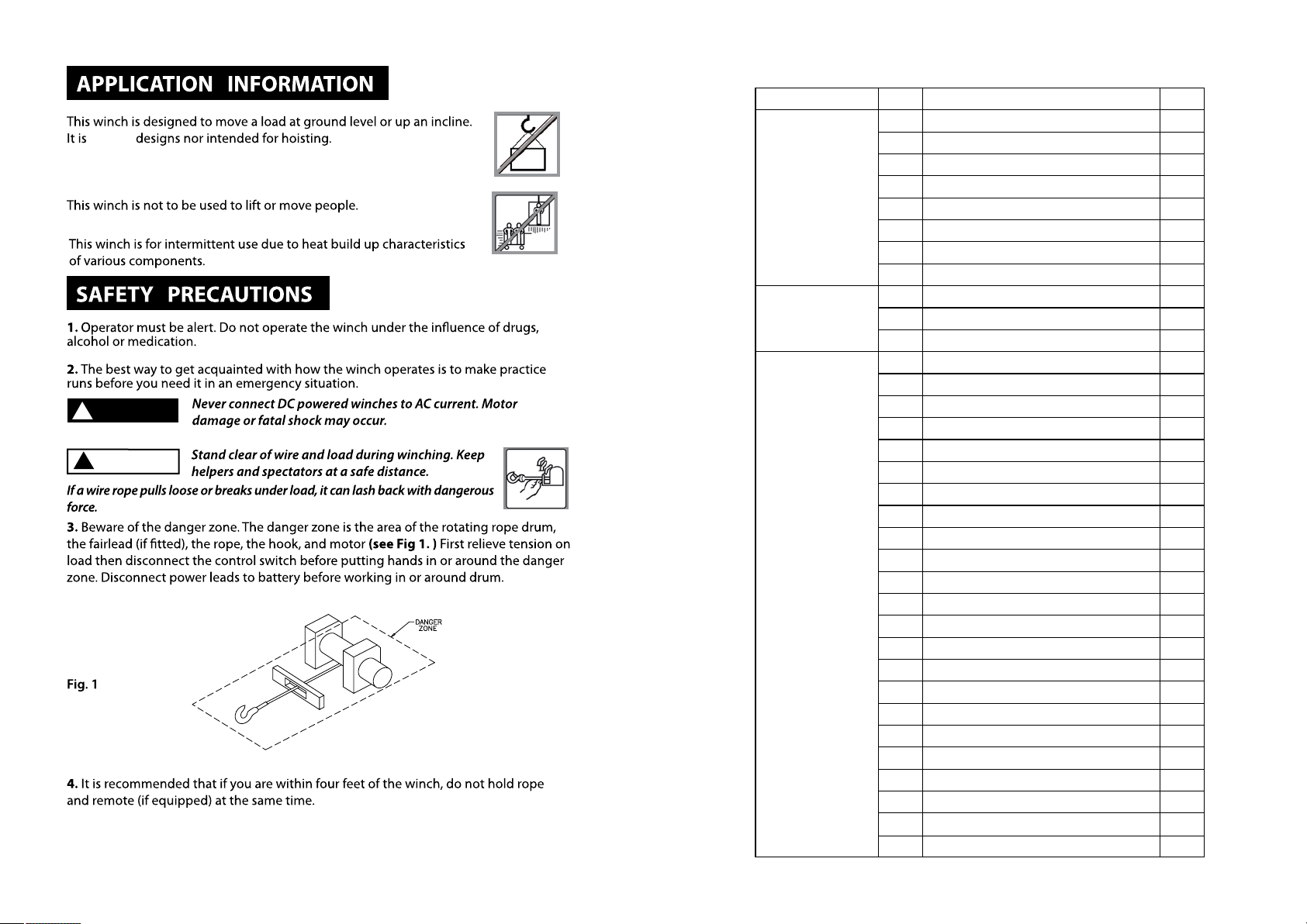
Please Note: Winch is designed primarily for intermittent applications. This winch is not
designed to be use in industrial or hoisting application and Novawinch does not warrant
it to be suitable for such use. Novawinch manufactures a separate line of winches for
industrial commercial use.
Congratulations on you choice!
Page 1
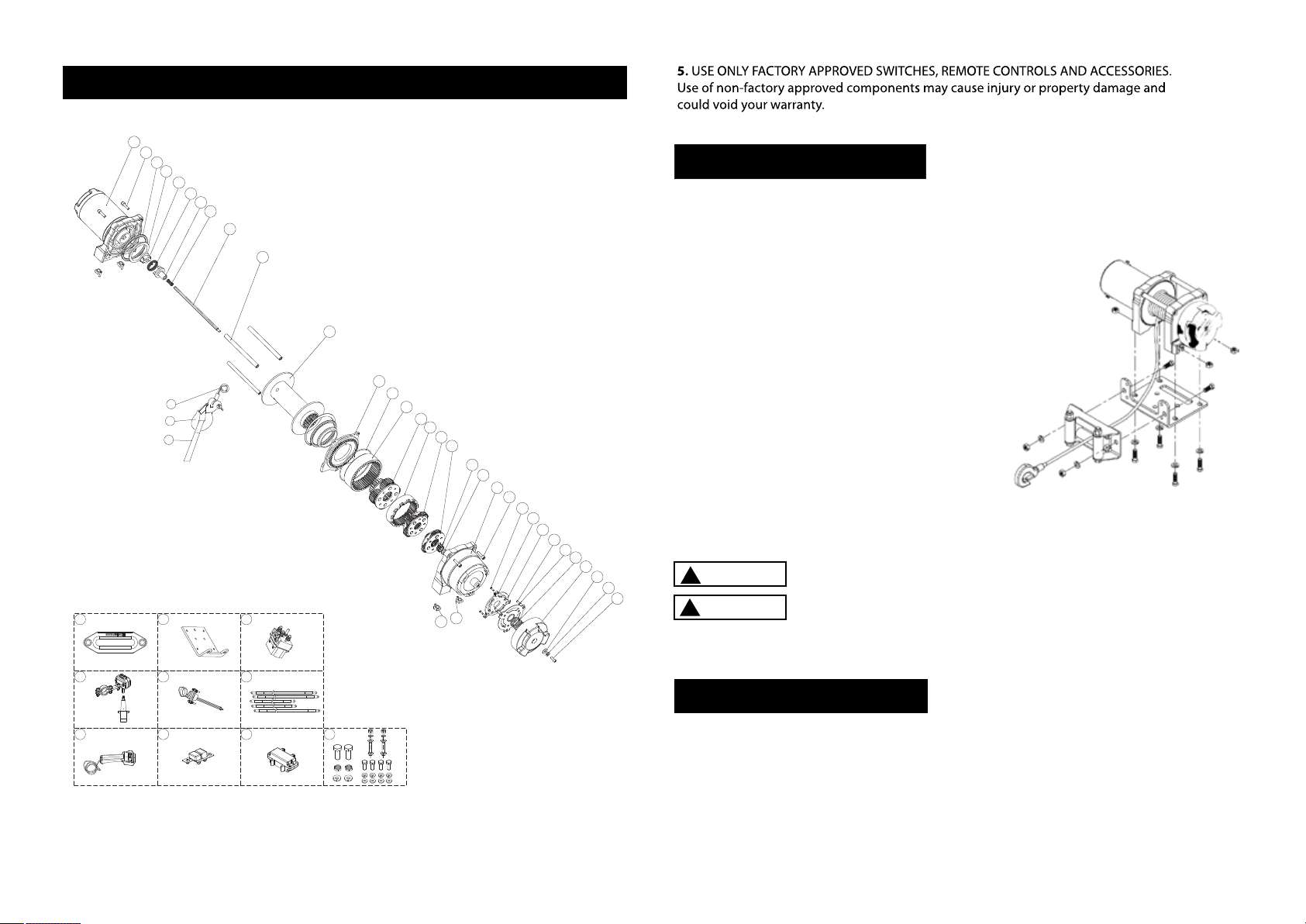
Synthetic Rope
Hook
Hand saver
Hawse Fairlead
Mounting plate
Solenoid
The thumb switch
The triangle plug
Cable set
Remote control
"Circiut breaker"
Circiut breaker cover
Screws and nuts
35
36
37
38
39
40
41
42
43
44
45
46
47
1
1
1
1
1
1
1
1
1
1
1
1
1
Synthetic Rope
Hawse Fairlead
Mounting plate
Solenoid
The thumb switch
The triangle plug
cables
Remote control
Circiut breaker
Hardware set
Page 40
Page 2
FENIX 4500SR-Parts list
"Hexagon socket cap screws M5*20"
Drum barrel
X-ring
Coupling I
"Rectangular spring"
Coupling
Spring φ4.8*18*0.8
Hexagonal drive shaft
Welded drum
Tie bar
Gear box cap
O ring
anti-wear gasket Ⅲ
3rd stage planetary gear assembly
2nd stage gear ring
2nd stage planetary gear assembly
1st stage planetary gear assembly
1st stage sun gear
Deep groove ball bearing
Gear box
hexagon socket head cap screws M5*25
Cross recessed countersunk head tapping screws ST3.5*12
"Clutch cam"
Clutch lever
O shape sealing ring Φ4.5*Φ1.5
Clutch soulplate
Clutch spring
Clutch handle
Clutch spring
φ5/flat washer
Cross recess pan head screw M5*10
Elastic cylindrical pin
Square nut
1
2
3
4
5
6
7
8
9
10
11
12
13
14
15
16
17
18
19
20
21
22
23
24
25
26
27
28
29
30
31
32
33
34
1
3
2
2
1
1
1
1
1
3
1
1
1
1
1
1
1
1
1
1
1
3
1
1
1
3
1
1
1
1
1
1
4
4
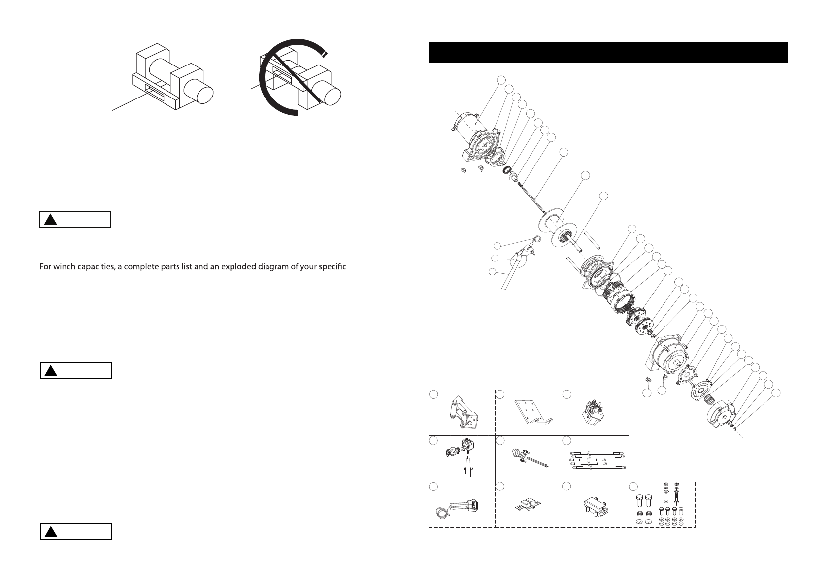
Drum Assembly
Gearbox
Assembly
Motor Assembly
No. Description Qty
Motor Assembly
Page 39
R
WARNING
!
DANGER
!
neither
Page 3
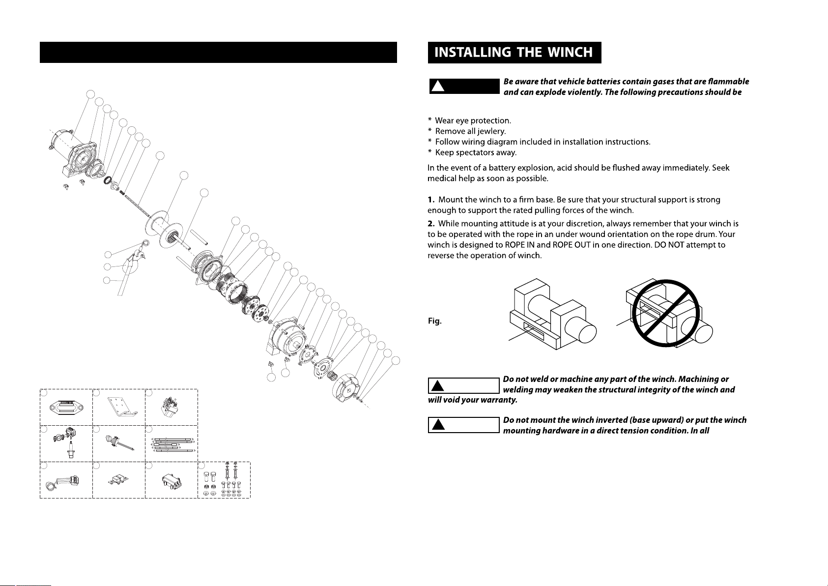
WINCH INSTALLATION
Step ( 3 )
Secure winch ( Fig. 2 ) to mounting kit or structural
support using bolts, lock washers and square
nuts supplied with winch.
Fig. 2 - Winch mounting
Step ( 4 )
Secure roller fairlead or hawse ( Fig. 2 ) to mounting plate or structural support using
hardware supplied
!
WARNING
!
CAUTION
!
Be sure that both the mounting plate and winch hardware have been
properly tightened.
No part of the vehicle ( skid plates, wiring, auxiliary lights, tires,etc. )
should impede the operation of your Novawinch. When mounting,
check all vehicle and winch parts for free operation. Be sure that the winch mounting
location does not significanty reduce ground clearance.
SOLENOID MOUNTING
1. The solenoid disconnects your winch from the battery when the vehicle is turned off.
2. The solenoid should be mounted close to the battery and in a location that is
clean and dry as possible.
Note: The solenoid should not be mounted in an orientation in which the contact
posts are in a downward position.
Explosion Drawing with 4500SR
1
3
4
5
6
7
8
9
10
11
12
13
14
15
16
17
18
19
20
2
21
23
24
26
27 28
29
30
31
22
25
34 33
32
35
36
37
44
41
38 39
42 43
45 46
40
47
Page 38
Page 4
3.Ensurethesolenoidlocation selected provides sufficient clearance form all metal
structures,such as frame tubes.
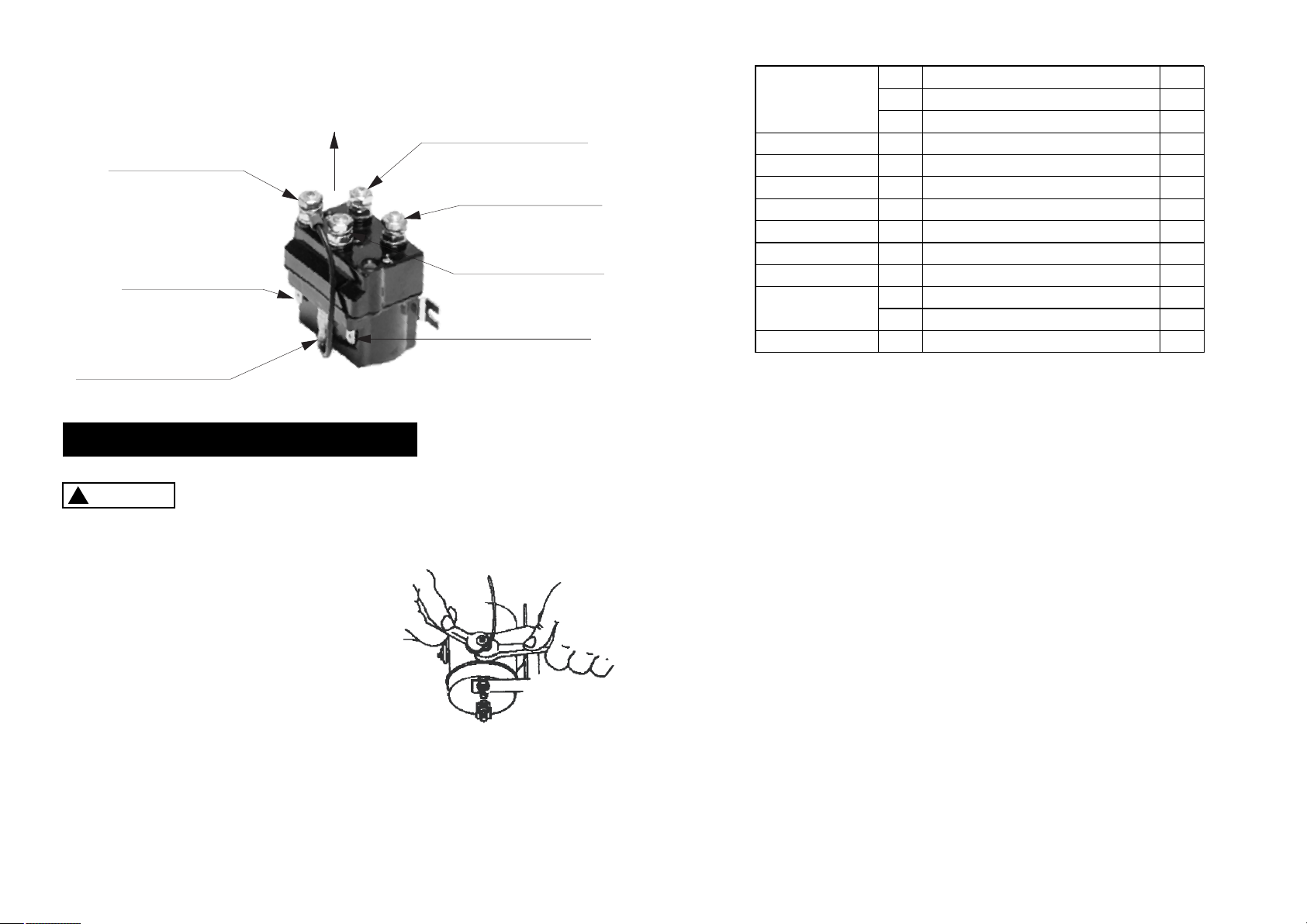
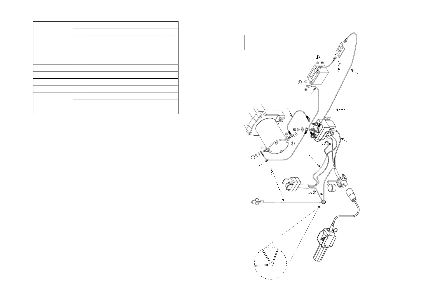
A.+ ,YELLOW wire #1 terminal
to motor positive “+”
B.- ,BLUE wire #2 to terminal
motor nagtive “-”
C. ,RDE wire to circute terminal
breaker unmarked side.
D. ,BLACK wire,toterminal
Battey Negative (-) Terminal.
E.Center spade connector,connects
the small black jumper wire,only,
(assembled as shown).
F.outerleftspade
connector,GREENwires.
G.outerrightspade
connetor,BLACKwires.
(Top of Solenoid)
TOGGLE SWITCH INSTALLATION
CAUTION
!
When attaching wires to the motor or solenoid terminals, hold the
inner nut with a wrench while tightening the outer nut with a second
wrench. Do not allow the terminals to rotate in their housings. Rotation may cause
internal wire breakage or part misalignment ( Fig 4).
Fig. 4 - Proper Terminal Tightening
Step ( 1 )
Check to ensure that the vehicle ground and positive leads from the battery are
disconnected before performing any electrical work.
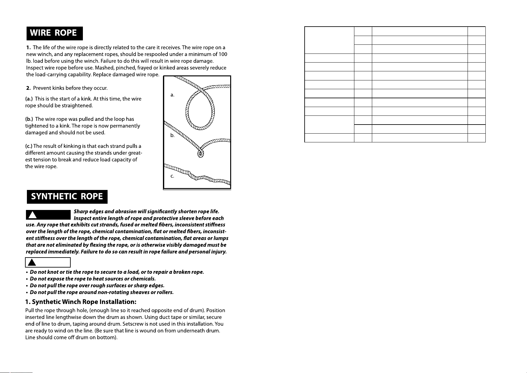
Wire Rope
Hook
Hand saver
Roller fairlead
Mounting plate
Solenoid
The thumb switch
The triangle plug
Cable set
Remote control
"Circiut breaker"
Circiut breaker cover
Screws and nuts
1
1
1
1
1
1
1
1
1
1
1
1
1
35
36
37
38
39
40
41
42
43
44
45
46
47
Wire Rope
Mounting plate
Roller fairlead
Solenoid
The thumb switch
The triangle plug
cables
Remote control
Hardware set
Circiut breaker
Page 37

Page 5
DANGER
!
DO NOT ATTEMPT TO INSTALL WIRING WHEN THE BATTERY IS
CONNECTED. Automotive batteries contain flammable and explosive
gases. Wear eye protection during installation and remove all metal jewelry. Do not lean
over battery while making connections.
Step ( 2 )
Route the wiring harness, attaching the harness to hard points on the vehicle with
cable ties.
Note: When routing the wires, the appropriate terminals should be located near the
battery, switch mounting point, and winch. Your installation requirements will vary
depending upon your vehicle and winch. Make sure wires are long enough to reach
the battery, switch mounting point and winch.
Step ( 3 )
Using the supplied clamps, bracket and hardware, mount switch in a convenient
location. See Fig. 5.
Fig. 5
Ensure that the wiring harness does not interfere or come in contact
with any hot or moving engine, suspension, steering, braking or
exhaust parts.
WARNING
!
ALWAYS USE THE SWITCH MOUNTING BRACKET, SCREWS, AND LOCK
NUTS PROVIDED. Screw lengths are sized for correct penetration into
switch box. Excess penetration may result in short circuits that could lead to wire over
heating.
CAUTION
!
Step ( 4 )
It is recommended that the switch be installed on the left handlebar.
Step ( 5 )
Once the switch is mounted, route the jacketed green and black leads back to where
the solenoid is mounted. Splice the red lead into wire that energizes with ignition
switch on and de-energizes with ignition off.
WIRING INSTALLATION
Step ( 1 )
Connect the YELLOW 6 ga. wire to the #1 “+” positive terminal on the motor and connect
the BLUE 6 ga. wire to #2 “-” negative terminal to the motor. (see Fig. 6)
Route the opposite ends of the YELLOW 6 ga. and the BLUE 6 ga. wires back to the
solenoid. On the top of the solenoid, connect the YELLOW 6 ga. wire to terminal A “+”
positive. Also, on top of the solenoid connect the BLUE 6 ga. wire to terminal B “-”
negative. (see Fig. 3)
FENIX 4500WR-Parts list
No. Description Qty
Motor Assembly
"Hexagon socket cap screws M5*20"
Drum barrel
X-ring
Coupling I
"Rectangular spring"
Coupling
Spring φ4.8*18*0.8
Hexagonal drive shaft
Welded drum
Tie bar
Gear box cap
O ring
anti-wear gasket Ⅲ
3rd stage planetary gear assembly
2nd stage gear ring
2nd stage planetary gear assembly
1st stage planetary gear assembly
1st stage sun gear
Deep groove ball bearing
Gear box
hexagon socket head cap screws M5*25
Cross recessed countersunk head tapping screws ST3.5*12
"Clutch cam"
Clutch lever
O shape sealing ring Φ4.5*Φ1.5
Clutch soulplate
Clutch spring
Clutch handle
Clutch spring
φ5/flat washer
Cross recess pan head screw M5*10
Elastic cylindrical pin
Square nut
1
3
2
2
1
1
1
1
1
3
1
1
1
1
1
1
1
1
1
1
1
3
1
1
1
3
1
1
1
1
1
1
4
4
1
2
3
4
5
6
7
8
9
10
11
12
13
14
15
16
17
18
19
20
21
22
23
24
25
26
27
28
29
30
31
32
33
34
Motor Assembly
Drum Assembly
Gearbox
Assembly
Page 36

Page 6
On the top of the solenoid, connect the RED 6 ga. wire to the terminal C.
Route the opposite end of the RED 6 ga. wire to the circuit breaker and connect the RED
6 ga. wire to the unmarked side of the circuit breaker. (see Fig. 6)
Step ( 2 )
Step ( 3 )
On the top of the solenoid, connect the BLACK 6 ga. wire to terminal D. (see Fig. 3)
On the solenoid, check that the short BLACK jumper wire lead, is installed from the
solenoid’s center at spade connector E, to the solenoid’s terminal D. (see Fig. 3).
Step ( 4 )
Step ( 5 )
Attach the BLACK wire from the rocker switch to the outer right spade,G connector, of the
solenoid.Attach the BLACK wire from the optional socket assembly to the same outer
right pade connector,G note;the solenoid top side up(see Fig.6 and 3)
Step ( 6 )
Attach the GREEN wire from the rocker switch to the outer left spade connector G on the
solenoid.Attach the GREEN wire from the optional socket assembly to the same outer
left spade connector G.note;the solenoid top side up(see Fig.6 and 3)
Step ( 7 )
Connect the RED WIRE, from the rocker switch and optionally from the socket assembly
to your ATV’s Ignition Switch key controlled wire. This wire must only have power when
the key is in the on position. A fuse protected key controlled wire is preferred. Fuse
should be rated for at least 4 amps. Cover-wind the connection with muti-layers of CE
approved electrical insulation tape, (see Fig. 6).
Connect the short RED 6 ga. wire to the end of the circuit breaker, marked positive.
Connect the other end of this RED wire to the “+” positive battery terminal. (see Fig. 6)
Step ( 8 )
Route the opposite end of the BLACK wire from, solenoid terminal D, and connect to the
“-” negative terminal on the battery. (see Fig. 6)
Step ( 9 )
Step ( 10 )
Check that all wiring is clear of sharp edges and pinch points. Check that all wiring is
firmly connected to it’s proper terminal or spade connector. Secure loose wiring with tie
wraps and electrical insulation tape.
1
3
4
5
6
7
8
9
10
11
12
13
14
15
16
17
18
19
20
2
21
23
24
26
27 28
29
30
31
22
25
35
36
37
34 33
32
44
41
38 39
42 43
45 46
40
47
Explosion Drawing with 4500WR
Page 35
1. +
2. -
Winch
Battery
Circuit Breaker
Solenoid
Socket
Assembly
Rocker
Switch
Hand held
Remote
YELLOW
6 ga. wire
BLUE
6 ga. wire
BLACK
6 ga. wire
RED
6 ga. wire
BLACK WIRE
GREEN WIRE
BLACK WIRE
MARKING
Fig. 6
Splice and tape
wires together
Motor
Vehicle Ignition
Key Switch
RED
WIRE
To Key Ignition
Switch, wire
To Rocker
Switch, wire
To Socket
Assembly, wire
Top
Page 7
Synthetic Rope
Hawse Fairlead
Mounting plate
Solenoid
The thumb switch
The triangle plug
cables
Remote control
Circiut breaker
Hardware set
Synthetic Rope
Hook
Hand saver
Hawse Fairlead
Mounting plate
Solenoid
The thumb switch
The triangle plug
Cable set
Remote control
"Circiut breaker"
Circiut breaker cover
Screws and nuts
35
36
37
38
39
40
41
42
43
44
45
46
47
1
1
1
1
1
1
1
1
1
1
1
1
1
Page 34

Page 8
!
WARNING
!
Before testing winch operation, be sure to reel off approximately
two feet of rope.
TEST DRIVE
1. Double check that all wiring is correct and that there are no exposed terminals that
can short to the vehicle frame.
2. Turn the ignition key to the ON position. Check winch for
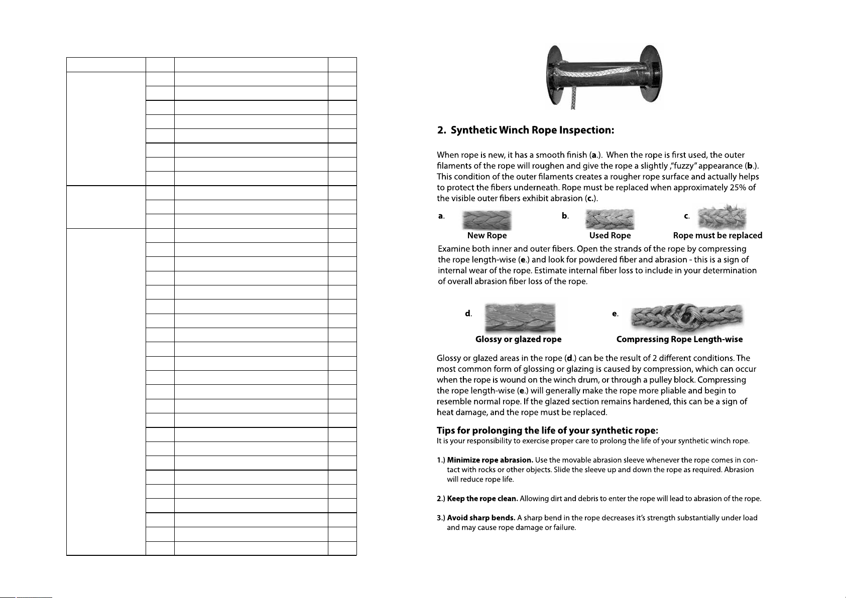
REMOTE SOCKET MOUNTING - optional
1. Determine the mounting location for the remote socket.
2. Drill three holes using the included dimensions as a guide.
3. Once the remote socket is mounted, route the jacketed green and black leads back
to where the solenoid is mounted. Splice the red lead to a key controlled electrical
wire on the ATV.
Fig. 7 - Socket Assembly mounts
from the outside, inward.
THE COMPLETE KIT
Winch
Solenoid
Rocker
Switch
Hand held
Fig. 8
Assembly
Socket
Drum Assembly
Gearbox
Assembly
Motor Assembly
No. Description Qty
Motor Assembly
FENIX 3500SR-Parts list
"Hexagon socket cap screws M5*20"
Drum barrel
X-ring
Coupling I
"Rectangular spring"
Coupling
Spring φ4.8*18*0.8
Hexagonal drive shaft
Welded drum
Tie bar
Gear box cap
O ring
anti-wear gasket Ⅲ
3rd stage planetary gear assembly
2nd stage gear ring
2nd stage planetary gear assembly
1st stage planetary gear assembly
1st stage sun gear
Deep groove ball bearing
Gear box
hexagon socket head cap screws M5*25
Cross recessed countersunk head tapping screws ST3.5*12
"Clutch cam"
Clutch lever
O shape sealing ring Φ4.5*Φ1.5
Clutch soulplate
Clutch spring
Clutch handle
Clutch spring
φ5/flat washer
Cross recess pan head screw M5*10
Elastic cylindrical pin
Square nut
1
2
3
4
5
6
7
8
9
10
11
12
13
14
15
16
17
18
19
20
21
22
23
24
25
26
27
28
29
30
31
32
33
34
1
3
2
2
1
1
1
1
1
1
3
1
1
1
1
1
1
1
1
1
1
3
1
1
1
3
1
1
1
1
1
1
4
4
Page 33
Page 9
Overwind
Underwind
CAUTION
!
CAUTION
!
installations, the unit must be mounted so that the rope feeds through the hawse or
rollerfairleadonthefrontofthewinch and does not rub across housings.
DANGER
!
taken before making battery connection:
Explosion Drawing with 3500SR
9,5
1
3
4
5
6
7
8
9
10
11
12
13
14
15
17
18
19
20
21
2
22
23
24
25
26
27 28
29
31
35
36
37
16
33
30
32
34
44
41
38 39
42 43
45 46
40
47
Page 32
9
Page 10
DANGER
!
!
WARNING
!
Wire Rope
Hook
Hand saver
Roller fairlead
Mounting plate
Solenoid
The thumb switch
The triangle plug
Cable set
Remote control
"Circiut breaker"
Circiut breaker cover
Screws ahd nuts
1
1
1
1
1
1
1
1
1
1
1
1
1
35
36
37
38
39
40
41
42
43
44
45
46
47
Wire Rope
Mounting plate
Roller fairlead
Solenoid
The thumb switch
The triangle plug
cables
Remote control
Hardware set
Circiut breaker
Page 31
Fig.10
Page 11
FENIX 3500WR-Parts list
"Hexagon socket cap screws M5*20"
Drum barrel
X-ring
Coupling I
"Rectangular spring"
Coupling
Spring φ4.8*18*0.8
Hexagonal drive shaft
Welded drum
Tie bar
Gear box cap
O ring
anti-wear gasket Ⅲ
3rd stage planetary gear assembly
2nd stage gear ring
2nd stage planetary gear assembly
1st stage planetary gear assembly
1st stage sun gear
Deep groove ball bearing
Gear box
hexagon socket head cap screws M5*25
Cross recessed countersunk head tapping screws ST3.5*12
"Clutch cam"
Clutch lever
O shape sealing ring Φ4.5*Φ1.5
Clutch soulplate
Clutch spring
Clutch handle
Clutch spring
φ5/flat washer
Cross recess pan head screw M5*10
Elastic cylindrical pin
Square nut
1
3
2
2
1
1
1
1
1
1
3
1
1
1
1
1
1
1
1
1
1
3
1
1
1
3
1
1
1
1
1
1
4
4
1
2
3
4
5
6
7
8
9
10
11
12
13
14
15
16
17
18
19
20
21
22
23
24
25
26
27
28
29
30
31
32
33
34
Motor Assembly
Drum Assembly
Gearbox
Assembly
No. Description Qty
Motor Assembly
Page 30
Fig.11

Page 12
WARNING
!
DANGER
!
Explosion Drawing with 3500WR
9,5
1
3
4
5
6
7
8
9
10
11
12
13
14
15
17
18
19
20
21
2
22
23
24
25
26
27 28
29
31
35
36
37
16
33
30
32
34
44
41
38 39
42 43
45 46
40
47
Page 29
12
12
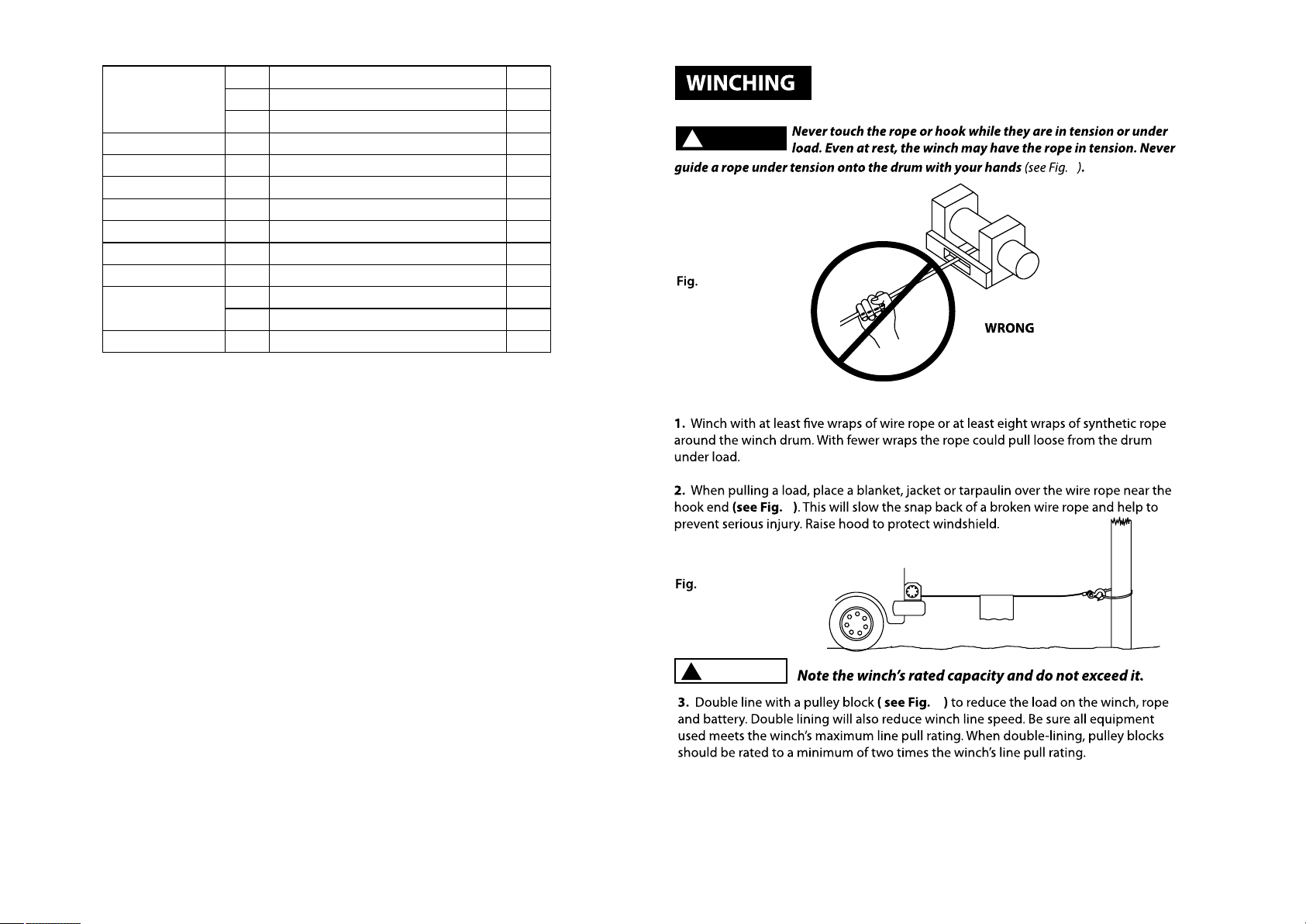
Fig. 6
WARNING
!
Page 13
DANGER
!
Synthetic Rope
Hook
Hand saver
Hawse Fairlead
Mounting plate
Solenoid
The thumb switch
The triangle plug
Cable set
Remote control
"Circiut breaker"
Circiut breaker cover
Screws and nuts
35
36
37
38
39
40
41
42
43
44
45
46
47
1
1
1
1
1
1
1
1
1
1
1
1
1
Synthetic Rope
Hawse Fairlead
Mounting plate
Solenoid
The thumb switch
The triangle plug
cables
Remote control
Circiut breaker
Hardware set
Page 28
13
14
14
13
15

Page 14
CAUTION
!
DANGER
!
WARNING
!
"Hexagon socket cap screws M5*20"
Drum barrel
X-ring
Coupling I
"Rectangular spring"
Coupling
Spring φ4.8*18*0.8
Hexagonal drive shaft
Welded drum
Tie bar
Gear box cap
O ring
anti-wear gasket Ⅲ
3rd stage planetary gear assembly
2nd stage gear ring
2nd stage planetary gear assembly
1st stage planetary gear assembly
1st stage sun gear
Deep groove ball bearing
Gear box
hexagon socket head cap screws M5*25
Cross recessed countersunk head tapping screws ST3.5*12
"Clutch cam"
Clutch lever
O shape sealing ring Φ4.5*Φ1.5
Clutch soulplate
Clutch spring
Clutch handle
Clutch spring
φ5/flat washer
Cross recess pan head screw M5*10
Elastic cylindrical pin
Square nut
1
2
3
4
5
6
7
8
9
10
11
12
13
14
15
16
17
18
19
20
21
22
23
24
25
26
27
28
29
30
31
32
33
34
1
3
2
2
1
1
1
1
1
1
3
1
1
1
1
1
1
1
1
1
1
3
1
1
1
3
1
1
1
1
1
1
4
4
Drum Assembly
Gearbox
Assembly
Motor Assembly
No. Description Qty
Motor Assembly
FENIX 2500SR-Parts list
Page 27
15
16
16

Page 15
WARNING
!
WARNING
!
CAUTION
!
DANGER
!
Explosion Drawing with 2500SR
9,5
1
3
4
5
6
7
8
9
10
11
12
13
14
15
17
18
19
20
21
2
22
23
24
25
26
27 28
29
31
35
36
37
16
34 33
30
32
44
41
38 39
42 43
45 46
40
47
Page 26
17
18
18
Page 16
WARNING
!
WARNING
!
Wire Rope
Hook
Hand saver
Roller fairlead
Mounting plate
Solenoid
The thumb switch
The triangle plug
Cable set
Remote control
"Circiut breaker"
Circiut breaker cover
Screwsandnuts
1
1
1
1
1
1
1
1
1
1
1
1
1
35
36
37
38
39
40
41
42
43
44
45
46
47
Wire Rope
Mounting plate
Roller fairlead
Solenoid
The thumb switch
The triangle plug
cables
Remote control
Hardware set
Circiut breaker
Page 25
19
19
20
20
21
Page 17
If you choose not to purchase a mounting kit, your Novawinch needs to be attached
to a secure and flat mounting location.Note that your winch may note be able to be
operated safely without some equipment included in the kit. If you choose not to
purchase a mounting kit, contact Novawinch for recommended accessories and the
name of a dealer near you.
mounting kit. Read and follow directions carefully.
This winch must be mounted with the rope in the under wound
direction ( Fig. 1 ) Improper mounting could damage your winch
CAUTION
!
and void your warranty.
CAUTION
!
MOUNTING YOUR WINCH
MOUNTING KITS
NOVAWINCH RECOMMENDS THE USE OF A MOUNT KIT FOR SECURE MOUNTING TO
YOUR VEHICLE. ATV Winch mounting kits are available from your Novawinch dealer
for nearly all ATV applications. For information on available kits, contact your
Novawinch product dealer, or go to www.Novawinch.net for the most current list
of kits.
"Hexagon socket cap screws M5*20"
Drum barrel
X-ring
Coupling I
"Rectangular spring"
Coupling
Spring φ4.8*18*0.8
Hexagonal drive shaft
Welded drum
Tie bar
Gear box cap
O ring
anti-wear gasket Ⅲ
3rd stage planetary gear assembly
2nd stage gear ring
2nd stage planetary gear assembly
1st stage planetary gear assembly
1st stage sun gear
Deep groove ball bearing
Gear box
hexagon socket head cap screws M5*25
Cross recessed countersunk head tapping screws ST3.5*12
"Clutch cam"
Clutch lever
O shape sealing ring Φ4.5*Φ1.5
Clutch soulplate
Clutch spring
Clutch handle
Clutch spring
φ5/flat washer
Cross recess pan head screw M5*10
Elastic cylindrical pin
Square nut
1
3
2
2
1
1
1
1
1
1
3
1
1
1
1
1
1
1
1
1
1
3
1
1
1
3
1
1
1
1
1
1
4
4
1
2
3
4
5
6
7
8
9
10
11
12
13
14
15
16
17
18
19
20
21
22
23
24
25
26
27
28
29
30
31
32
33
34
Motor Assembly
Drum Assembly
Gearbox
Assembly
No. Description Qty
Motor Assembly
FENIX 2500WR-Parts list
Page 24
21
22
Page 18
MINIMUM ELECTRICAL REQUIREMENTS
Refer to specifications for your winch model in the Technical Data Manual in this
age. Be sure to select the appropriate battery or power supply to handle this winch. If
the winch is in heavy use, an auxiliary battery and heavy duty alternator are
recommended.
INSTALLATION PROCEDURE
Step ( 1 )
Install mounting kit or prepare a flat, secure mounting location for winch to make sure
the motor, drum, and gearbox are aligned correctly. Carefully follow the instructions
included with the mounting kit.
!
WARNING
!
Be sure structural support is strong enough to support rated
capacity of the winch.
battery.
!
Fig. 22
Overwind
Underwind
Note: It is possible and not uncommon or discouraged to mount your Novawinch in
attitudes other than those shown in this installation manual. While mounting attitude
is at your discretion, always remember that your winch is to operated with the rope
in an under wound orientation on the rope drum ( Fig. 22 ) Your winch is designed to
ROPE IN and ROPE OUT in one direction. Do not attempt to reverse the operation of
your winch.
Do not mount winch inverted, (base upward) or put the
winch mounting hardware in direct tension condition. In all
installations, the unit must be mounted so that the rope feeds through the hawse
or roller fairlead on the front of the winch and does not rub across housings.
CAUTION
!
Novawinch, refer to the Technical Data Sheet included in this package.
For instructions on safe winch operation and tips for prolonging the life of your winch,
refer to the Safty precautions included in this package.
Note: When installing a winch, your installation may vary slightly from the instruc-
tions and diagrams that follow, depending upon your vehicle, winch, mounting kit or
structural support.
!
WARNING
!
Before you start your Novawinch installation, disconnect the
vehicle ground and positive leads from the
Explosion Drawing with 2500WR
9,5
1
3
4
5
6
7
8
9
10
11
12
13
14
15
17
18
19
20
21
2
22
23
24
25
26
27 28
29
31
35
36
37
16
33
30
32
34
44
41
38 39
42 43
45 46
40
47
Page 23
This manual suits for next models
2
Table of contents
Other NOVAWINCH Winch manuals

Popular Winch manuals by other brands

Paccar Winch
Paccar Winch Braden PD35A Installation maintenance and service manual

Comeup
Comeup CP-500T quick start guide

Lux Tools
Lux Tools SW-360 manual

Mile Marker
Mile Marker HI9000 Installation and operator's manual

Warn Industries
Warn Industries 12-A-48 Series quick start guide

Comeup
Comeup CP-200 Assembly


