Uniforest 85MR User manual

1
Instructions for use
FORESTRY WINCH
85MR
Instructions for safe work
Spare parts list
THE MANUFACTURER:
Uniforest d.o.o.
Latkova vas 81d
3312 Prebold
www.uniforest.si
Valid from serial number:
85MR
11614000224

2
GENERAL
Dear customer!
We would like to congratulate you for the purchase of our machine. The hydraulic forestry
winch is a forestry machine with a modern design and a construction which enables
efficient and safe work in the woods. Work in the woods can only be safe if you observe
the instruction for safe use. If you follow the instructions the machine will work perfectly
and there will be no unnecessary expenses.
We recommend you to carefully read the user manual. In case of doubt do not hesitate
to contact us.
We wish you safe work with the machine.
1. Index
GENERAL .........................................................................................................................................2
1. Index...................................................................................................................................2
2. Intended use .....................................................................................................................3
3. Tehnični podatki:...............................................................................................................3
SAFETY INSTRUCTIONS....................................................................................................................4
INSTRUCTIONS FOR USE..................................................................................................................8
1. Description.........................................................................................................................8
2. Required equipment of the tractor.................................................................................8
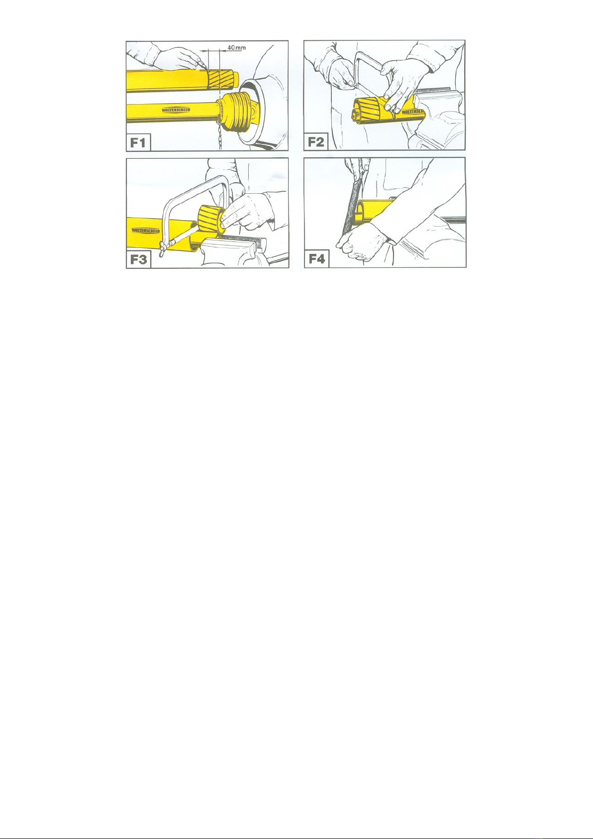
3. Pto shaft adjustment.........................................................................................................8
4. Tractor mounting...............................................................................................................9
5. Wire rope unwinding.........................................................................................................9
6. Towing ..............................................................................................................................10
SETTINGS........................................................................................................................................11
1. Clutch...............................................................................................................................11
2. Safety brake ....................................................................................................................11
3. Brake ................................................................................................................................11
4. Drive chain tensioning....................................................................................................13
7. Wire rope assembly.........................................................................................................14
MAINTENANCE LUBRICATION.....................................................................................................14
TROUBLESHOOTING ......................................................................................................................15
EC DECLARATION OF CONFORMITY ...........................................................................................17
Spare parts list..............................................................................................................................18

3
2. Intended use
The machine is designed exclusively for normal work in the woods. Any other use is considered
as unintended. This winch can only be used for pulling loads on the ground. The
manufacturer is not liable for any damage resulting from inappropriate use. In this case, the
user takes all responsibility. Intended use also includes observing operational, handling and
maintenance conditions specified by the manufacturer. The machine can be operated only
by a person who is qualified and informed about the dangers and consequences of
inappropriate use. Relevant safety regulations as well as general regulations on technical
safety of devices, health regulations and road rules must be observed. The manufacturer is
not liable for any damages that may arise from users making unauthorized changes on the
machine.
3. Tehnični podatki:
Unit
85M
Working group
EM
1
Pulling force
kN
85
Brake force
kN
106,25
Wire rope medium speed
m/s
0,60
Wire rope maximum
length
mm/m
10/120
11/105
mm/m
12/90
Wire rope length (serial)
mm/m
11/70
Tractor
required power
kW
min. 50
KM
min.68
Tear force
kN
160
Rated strength
N/mm2
2160
Width
mm
1800
Depth
mm
780
Height without protective net
mm
1830
Height with protective net
mm
2300
Weight(without wire rope)
kg
571
Revolutions on cardan
min-1
max. 540
Wire rope
diameter
Manufacture year
Serial no.
c
c
Pulling force at the
internal diameter
of the drum
Pulling force at the
external diameter
of the drum
Operating pressure
Wire rope
length
Min. breaking
force
Specific min.
breaking force
Max. PTO shaft
revolutions
Weight of the
machine
Machine type

4
SAFETY INSTRUCTIONS
When working with the winch you need to observe the safety instructions!
In order to prevent accidents carefully read and observe the following instructions:
1. General:
1. Apart from the instructions in this user manual you should also observe all general safety
and accident preventing regulations.
2. When working with the winch, it is necessary to comply with the rules of safety at work.
3. Only persons, who are older than 18, are allowed to work with the winch.
4. Safety and warning plates on the machine provide important instructions for safe use.
Observe them for your safety.
5. The winch or its flawless operation should be checked before every use or at least
once every working day. Defects should be removed by an expert. Before first use or
after significant alterations and at least once a year the winch must be examined by
an expert.
6. When using public transport routes observe traffic signs and regulations.
7. When using the winch wear personal protective equipment(helmet, gloves,
appropriate footwear,...).
8. Before starting and driving check the surrounding area (children). Maintain adequate
visibility.
9. Riding on the winch during transport is not allowed.
10.Connect the winch according to the instructions.
11.For on road travel the machine must be in the following condition. If the winch covers
the rear lights of the tractor and they are not visible during transport on public roads,
install additional lights on the winch.
12. Adjust the driving speed to the environmental conditions. When driving up or down or
across a slope avoid sudden turning of the steering wheel.
13. Do not stand in the danger area.
14. If the tractor is not blocked against moving with a brake or wheel blocks, no person
should be standing between the tractor and the winch.
15. Do not touch the winch until every part of the winch has stopped.

5
16. Check mounting bolts regularly.
17. Before use the winch must be visually inspected. At least once a year, the winch must
be inspected by a professionally qualified person.
18. During any work on the winch you must turn the tractor off.
19. It is forbidden to remove the safety devices from the winch.
20. Use a tow rope of adequate strength and quality (see the factory plate).
21. A damaged wire rope must be replaced immediately.
22. It it necessary to use a wire rope of an appropriate lenght. When you wind the rope
up, a distance of 1,5 of rope diameter to outer diameter of the drum should stay on
the drum. When you unreel the rope, a minimum of 3 rope wraps should stay on the
drum.
23. The assistant is not allowed to connect load on the winch until he has informed the
tractor driver about it.
24. It is especially dangerous to stand next to the tree that you are about to pull (Figure 1).
25. When using a relay pulley there is a triangular danger area, where you are not
allowed to stay during the tow (Figure 2).
Figure 1 Figure 2
26. When towing observe the maximum allowed angle of 30º (Figure 3).
27. On uneven terrain or when not observing the maximum allowed towing angle there is
a danger of the winch rolling over (Figure 6).
Figure 3 Figure 4 Figure 5
28. Do not use the winch for unintended purposes (lifting loads, etc.).(Figure 5)
29. Tractor driver and assistant must continuously communicate during their work.

6
30. The winch operator must continuosly observe the load during the tow. If this is not
possible due to the configuration of the terrain, the assistant should help.
31. The tractor to which the winch is connected to must have a minimum tyre profile
which still meets the traffic regulations. Otherwise the wheels must be fitted with snow
chains. Chains are also obligatory when working in snow and ice.
32. When disconnecting the winch, you first need to choose an appropriate hard and flat
surface. Fix the winch by means of support legs. Lean the drive shaft on the prepared
holder.
33. In the area of the three point linkage there is a danger of injuries due to compression
or crushing.
34. The winch can be operated only from a safe place from which the load, wire rope,
rope hook or the winch itself do not pose a threat to the operator. A safe place can
also be the tractor seat if the winch has a safety net of sufficient size. When operating
the winch outside the tractor seat the operator must be provided with an appropriate
protection, e.g. the tractor itself, secure location at a sufficient distance from the
vehicle, e.g. behind a tree. Logs can be monitored from the side next to the
connection and shorter timber can be monitored diagonally behind the load. (See
Figure 6).
35. During the tow, it is forbidden to stand between the load and the winch as well as in
the danger area between the winch, relay pulley and load. (See picture 7).
36. Before operating the winch, make sure that the winch butt plate is securely anchored
to the ground. In the event of soft ground, steep slopes or when pulling heavy loads,
the tractor must be fastened with an additional rope or chain. This will prevent the risk
of slipping or even overturning of the tractor.
37. Adjust the speed of load pulling and the size of the load to the tractor’s power
capacity. You should also pay attention to the inclination of the slope and the terrain
to avoid a rollover and to maintain a safe steering and braking performance.
38. The hitch on the winch is designed as a work tool and should not be used on public
roads

7
Figure 6 Figure 7
CARDAN SHAFT
1. Only use such cardan shafts which are recommended by the manufacturer.
2. The cardan shaft protection pipes, protective funnels and attachment protection
must be mounted on the machine and be in perferct condition.
3. Observe the recommended pipe protection in transport and working position.
4. The cardan shaft can only be connected or disconnected, when the cardan
attachment is turned off, the engine has stopped and the ignition key has been
removed.
5. The cardan shaft must always be properly mounted and protected.
6. Secure the cardan shaft agains rotating with a chain.
7. Before switching on the cardan shaft on the tractor make sure that the chosen
speed and direction of rotation match the requirements from the chapter
Technical data.
8. Before switching on the cardan shaft make sure no person is standing in the danger
area of the machine. This rule must also be observed during machine operation.
9. Never switch on the cardan shaft when the engine is turned off.
10.Put the disconnected cardan shaft on the intended holder.
Danger area
Tree
Triangle
area
Oscillating rope
Torn–off pulley
Pulley
Tow rope

8
INSTRUCTIONS FOR USE
1. Description
A winch is a machine intented for harvesting felled timber from the forest. The basic
components are: welded frame, drive part, drum with wire rope, clutch, brake and
directional pulley. Using the wire rope, the logs can be towed to the moldboard and
attached with forestry chains to the grooves on the winch frame. Then the logs can be
transported to a place which is accessible by other means of transport.
2. Required equipment of the tractor
-PTO shaft with chosen gear ratio, max. 540 RPM.
-Three-point hitch of I and II category.
Maximum number of revolutions and direction of tractor PTO shaft rotation is 540 min-1.
3. Pto shaft adjustment
Length of PTO shaft needs to be adjusted for different tractors (figure F1-F4). For winch
85MR, the use of PTO shaft with torque 695 Nm (type W 400E Walterscheid) is appropriate.
Ascertain the accurate length in the following manner:
1. Shut down the tractor.
2. Connect the machine to the tractor.
3. Extract the PTO shaft apart and connect the individual shaft halves to the tractor
and machine and compare them crosswise and mark them (figure F1).
4. Shorten external and internal plastic protection pipes (figure F2).
5. Shorten external and internal slide profiles with the same distance as plastic
protection pipes (figure F3).
6. Crop the pipe end, remove fillings and grease the slide positions well (figure F4).

9
4. Tractor mounting
When connecting the winch, do not stand in the danger zone!
The forestry winch can be attached to every tractor with a three-point hitch with a
category I or II coupling. Appropriate construction also enables easy connection to the tractor
with automatic connection rods. Connect the prescribed PTO shaft and secure cardan protection
with a hang chain.
Be careful that the cardan clicks into place on both connection points!
Once the winch is attached to the tractor, strengthen the stabilizers on the lower connection rods
and level the winch with a hitch nut into position, so that the winch is tilted backwards for
approximately 20 degrees.
5. Wire rope unwinding
Warning
Steel rope must be completely unwound before first use and wind it back on the
generator drum under load.
For instance, we can do this so that we attach the rope to a standing tree and pull the
tractor with slight braking to the tree. This procedure must be done also before trying to
tow, if we towed downhill beforehand or if the rope was wound loosely during towing.

10
ATTENTION!
Loosely wound steel rope can be damaged (stuck, bent) at greater load, so that it is
prohibited to use it again.
Warranty does not apply for a steel rope, which is damaged in such manner.
Once the winch is properly connected to the tractor, you can start unreeling the wire
rope. Pull the wooden lever on a red string (pos. 3, figure 11) and thus move lever 2 to the
OFF position (figure 11). The brake is released and the wire rope can be unreeled. In case
you have just installed the wire rope on the drum or you have noticed that the wire rope is
not installed properly, you should unreel the entire wire rope and then reel it back tightly,
as described in the beginning of this chapter.
6. Towing
Figure 9
Lower the winch on the ground so that the winch is supported by a hard surface. Engage
the hand brake. Never start towing if a winch is not in a stable position on the ground.
Before you pull the black string (pos. 10, figure 11), check that the string is installed
properly between the small pulleys (pos. 9, figure 11). The lever (pos. 1, figure 11) should
return to its original OFF position as soon as you stop pulling the string (pos. 10, figure 11).
If this string is not wound properly, it may happen that you will not be able to stop the
towing, which can lead to an accident.
Any interference with the activation mechanism which would prevent synchronous
operation of clutch and brake is prohibited. It is also forbidden to pull the red brake string
(pos. 3, figure 11) during the towing.
It is forbidden to lift the hydraulic linkage during the towing (it can lead to a malfunction of
the PTO shaft).

11
SETTINGS
1. Clutch
A properly set clutch enables optimal traction force. The clutch was factory set during the
testing of the winch, but due to friction surface wore, it eventually must be set anew.
The re-setting is not permitted within the warranty period!
Install a dynamometer on the black string. In case you do not own a dynamometer, you
can also use a spring balance with an appropriate weighing range.
Once you have installed the dynamometer (spring balance), pull the string with a force of
350 N (35 kg) and check the position of the lever (pos. 1, figure 11). This lever can be seen
in figure 11a. Use the nut on the main shaft (pos. 8, figure 11) to regulate the position of
the lever (pos. 1), until the lever is not touching the backrest.
In case you tightened the nut too hard (pos. 8, figure 11) and the lever moved away from
the backrest, the necessary axial force on the friction surface of the clutch has been
reduced too much.
The winch will not be able to reach to necessary traction force and the friction surface of
the clutch will be damaged due to sliding.
2. Safety brake
Use a screw (pos. 6) and a lock nut (pos. 7, figure 11) to set the safety brake. First loosen
the lock nut and regulate the screw (pos. 6). By turning the screw clockwise, you increase
the brake force and by turning the screw anti-clockwise, you decrease the brake force.
Then tighten the lock nut which prevents the screw from becoming loose. A proper setting
means that the wire rope will not unreel from the drum automatically or too easily. This
can lead to wire rope damage when you release the brake and start unreeling the wire
rope. The safety brake is set properly when the wire rope can be unreeld without too
much effort. In case you are pulling the rope up a slope, it is possible to additionally
relieve the brake so that the pulling of the rope is easier. But after you finish the work, the
safety brake must be returned to its original position (as describe above).
3. Brake
The brake is set via a nut (pos. 5, figure 11). The brake lever (pos. 2) must be in the ON
position (figure 10). First use a wrench key to loosen the nut (pos. 4), then turn the nut with
a wrench key(pos. 5) to the left to tighten the brake belt. Turn the nut to the right to
loosen the brake belt. For optimal operation the gap between the nuts must be 24 mm. If
the brake force is not sufficient, repeat the procedure and tighten the nut (pos. 5) to the
left. At the end, tighten the nut (pos. 4) to an appropriate gap. If the set braking force is
too high, the unreeling of the rope is more difficult. In such cases, turn the nut to the right.

12
Figure 10
Figure 11
Figure 11a (lever rest)

13
4. Drive chain tensioning
After a certain period of operation (10 hours), the drive chain stretches; therefore it must
be checked frequently and tensioned, if required. It must be checked every 100 hours of
operation. Tensioning is done according to the following procedure (figure 12)! First,
disengage the PTO shaft and turn off the engine. Remove the protective sheet of the PTO
shaft (pos. 1).
First loosen the nust (pos. 2 and pos. 8, figure 12) with which the lower and upper drive are
fixed. Then start tigthening the longer chain with a screw (pos. 5). Turn the screw clockwise
until you reach the proper tension of the chain. The chain is correctly tensioned when it
can still oscillate for 3 to 4 mm in the transverse direction. Tighten the lock nut (pos. 12).
Now tighten the three nuts on the lower drive (pos. 2). Then start tensioning the shorter
chain (pos. 7, figure 12). If you have already loosened the four nuts (pos. 8), begin with the
turning of the tensioning screw (pos. 10) to the left. This increases the distance between
both frames. Beforehand, loosen the lock nut (pos. 11) and re-tigthen it when the chains
are tensioned.
Figure 12

14
7. Wire rope assembly
First, remove the triangular protective net on the winch column. Then rotate the cover
(pos. 12, figure 11) and rotate the drum in a position, which enables
unscrewing of the bolt (pos. 11)on the drum. Insert the wire rope in the guide of the upper
pulley and direct it through the upper pulley to the rope drum. Insert the rope in the
groove and tighten the bolt (pos. 11, figure 11). Then start to wind according to the
procedure, which applies to towing. Once the entire length of the wire rope is wound,
unwind it again and wind it again strongly according to the procedure, which is
described in the chapter “Wire rope unwinding” to prevent damage to the rope.
MAINTENANCE LUBRICATION
Before proceeding with maintenance work, shut down the engine,
remove the key and wait for all moving parts to stop.
There is a grease fitting on the winch, which enables greasing of the upper pulley and
guide. The second grease fitting is on the housing of the lower pulley. Greasing is required
every 60 hours of operation. The PTO shaft needs to be lubricated according to
instructions of the manufacturer. Non-frequent greasing can cause wear of slide elements
and consequentially a defect, which is not subject to warranty terms!
Drive chain must be lubricated every 100 hours of operation. Lubricate it with spray for
lubrication of chains or special grease, which does not melt at high temperatures,
because the grease can come into contact with friction coating of the clutch.
First, remove the cardan shaft protection, which must be fitted back after finishing
lubrication. Clean the chain before lubrication. Do not lubricate the part, where the
grease can reach clutch with application.
If grease comes into contact with friction coating of the clutch due do improper and
excessive lubrication, this would mean a drastic reduction in pulling force and
consequentially it would be required to replace the blades of the clutch, which cannot be
a subject of this warranty!
All other bearings on the winch are of closed type, therefore greasing is not necessary. Grease
the PTO shaft according to the instructions of the manufacturer.

15
TROUBLESHOOTING
Identified malfunctions
(errors)
Cause
Elimination of malfunctions
(errors)
Lack of traction force
Grease on the friction
surfaces of the clutch
Replace the clutch
Burned friction surfaces of
the clutch
Clean or polish the coating with
sandpaper (to a thickness of 0,5
mm)
The pressure in the hydraulic
system is too low (the
necessary pressure os 140
bar)
Determine the cause for low
voltage
Worn friction surfaces of the
clutch
Replace the clutch
Incorrectly installed clutch
Install according to technical
documentation
Insufficient braking force
Incorrect settings
Set according to instructions for
use
Grease on the brake belt
coating
Replace brake belt
Damaged brake belt
Replace brake belt
Damaged braking
mechanism
Replace damaged parts
Other
Contact customer service
The wire rope cannot be
unreeled or the
unreeling is difficult
Incorrect safety brake
setting
Set according to instructions for
use
Incorrect brake settings
Set according to instructions for
use
Damaged or stuck wire rope
Unreel the rope with a tractor
and if necessary, install new wire
rope
Damaged brake belt
Replace brake belt
Improper position of the
brake lever
Observe the instructions for use
Damaged or corroded
activation mechanism
Grease the activation
mechanism with a WD spray or
replace the activation
mechanism if necessary
Other
Contact customer service
The winch is pulling
Electromagnetic valve
Stop work immediately and

16
although the clutch is
turned of
malfunction
contact customer service
Too small clutch clearance
Set according to instructions for
use
Broken part of clutch friction
coating
Replace the clutch
Damaged winch drum
Replace or repair the drum
Drive belt is too tight
Tension the belt as described in
the instructions for use
Winch is very loud
during operation
Drive belt is too tight
Tension the belt as described in
the instructions for use
Damaged or worn bearings
Replace bearings

17
EC DECLARATION OF CONFORMITY
IN COMPLIANCE WITH:
DIRECTIVE 2006/42/ES AND THE MACHINERY SAFETY RULES
(OFFICIAL GAZETTE OF RS, NR. 75/08, 66/10 and 74/11)
MANUFACTURER:
UNIFOREST D.O.O.
Latkova vas 81d, 3312 PREBOLD, SLOVENIJA
PERSON RESPONSIBLE FOR TECHNICAL DOCUMENTATION:
MARKO POLAK, UNIV.DIPL.INŽ., UNIFOREST,
Latkova vas 81d, 3312 PREBOLD
DESCRIPTION OF DEVICE - MACHINE:
WINCH:
UNIFOREST 45M, 45MR, 55M, 55MR, 85MR
WE DECLARE UNDER OUR SOLE RESPONSIBILITY THAT THE ABOVE MENTIONED MACHINE
WINCH:
UNIFOREST 45M, 45MR, 55M, 55MR, 85MR
IS COMPLIANT WITH THE FOLLOWING REGULATIONS AND STANDARDS:
DIRECTIVE 2006/42/EC AND THE MACHINERY SAFETY RULES
(OFFICIAL GAZETTE OF RS, NR. 75/08, 66/10 and 74/11)
HARMONISED AND OTHER STANDARDS:
SIST EN ISO 12100:2011 SIST EN ISO 4254-1:2010/ AC:2011
SIST EN ISO13857:2008 SIST EN ISO 4413:2011 ÖNORM L5276:2008
DATE: SIGNATURE OF RESPONSIBLE PERSON:
Prebold, 11. 04. 2019 MARKO POLAK, UNIV.DIPL.INŽ.

18
Spare parts list
Figure 1: 7001.05.30.0 –Brake and clutch mechanism.

19
Pos.
Name
No. of
pieces
Number
1
Pulley, small, single
1
502.00.40.0
2
Pulley, small, single 2
1
502.00.42.0
3
Pulley, small, double, wide
2
502.00.43.0
4
WOODEN HANDLE
2
502.00.56.0
5
NYLON ROPE (red) 7mm - 5,5m
1
1000554
6
Clutch roller
3
502.11.15.0
7
Clutch lever spring
1
502.11.25.0
8
Brake band
1
702.61.00.0
9
Activation mechanism
1
5002.05.08.0
10
Lever link
2
5002.05.43.0
11
Brake lever var.
1
5002.05.45.0
12
Automation system kpl.
1
5002.05.50.c
13
Compression spring
1
5006.05.36.0
14
Band brake screw Zn
1
5006.05.37.0
15
Pre-brake nut
1
5006.05.38.0
16
Clutch lever
1
7001.05.05.A
17
Fork kpl
1
7001.05.15.0
18
Automation system coupler
1
7001.05.41.A
19
NYLON ROPE (black) 7mm - 6,5m
1
7001.05.43.0
20
Brake plate
1
7002.05.12.0
21
Brake plate
1
7002.05.13.0
22
Pre-brake bolt
1
7002.05.42.0
23
Band bolt 65
1
7002.05.43.0
24
Screw M8x16 Zn
2
1000050
25
Hexagon socket screw M18x12
2
1003453
26
Screw M8x55 Zn
2
1000041
27
Screw M12x60 Zn
1
1000076
28
Screw M12x70 Zn
1
1001148
29
Screw M12x35 Zn
2
1000058
30
Screw M6x30 Zn
1
1011373
31
Screw M8x20 Zn
2
1000051
32
Screw M8x25 Zn
2
1000052
33
Washer M8 Zn
4
1003473
34
Nut M8 Zn
7
1003460
35
Nut M12 Zn
2
1000142
36
Nut M12 Zn
2
1000139
37
Nut M6 Zn
1
1003712

20
Figure 2: 7001.05.15.0 –Brake fork.
Pos.
Name
No. of
pieces
Number
1
Bolt
1
7002.05.14.0
2
Brake spring
1
5002.05.40.0
3
Spring washer
1
5002.05.23.0
4
Brake bush
1
7001.05.24.0
5
Brake tube
1
7001.05.26.0
6
FORK VAR.
1
7002.05.20.0
7
Screw M14x280 Zn
1
1016830
8
Nut M14 Zn
3
1003629
9
Nut M14 Zn
1
1000035
This manual suits for next models
1
Table of contents
Other Uniforest Winch manuals
Popular Winch manuals by other brands

Ingersoll-Rand
Ingersoll-Rand FORCE5i FA5i-MRA Product information

pela tools
pela tools H2500 quick start guide

Tulsa
Tulsa RUFNEK 15 Service manual

Dutton-Lainson
Dutton-Lainson B1200G Original instructions

Andersen
Andersen 28 STE manual

HADEF
HADEF 42/87P Installation, operating, & maintenance instructions