NOVAWINCH CH500 User manual
PLEASE READ CAREFULLY BEFORE OPERATE THE WINCH
2020.09.10
ELECTRIC WINCH
1689 Xianyuan Road,Jinhua,Zhejiang,China
Tel:0086-579-82262697
Fax:0086-579-82262706
E-mail: info@nowvow.net
http://www.novawinch.net
CH500

DESCRIPTION
UNPACKING
The CH series electric winch is for intermittent duty only. Motor cool-down time is
required. Can be mounted horizontally or vertically. Winch can beutilized in a variety
of lifting operations involving machinery, trucks, boats, farm implements, etc.
Equipped with DC motor, permanently lubricated/sealedgear box, switch with
harness assembly. For additional information, consult Specifications and Performance.
Please unpack carefully and read the instructions before beginning. Inspect carefully
for any damage that may have occurred during transit. Check for loose, missing or
damaged parts.
This equipment must be used as recommended by the manufacturer. Failure to follow
these recommendations could endanger your life or cause property damage.
DANGER
Page 1 Page 14
CH500-Parts list
Mounting Plate
No. Description Qty Remark
Electric Motor
Assembly
Gearbox Assembly
Drum Assembly
Tie Bar Assembly
Accessories
Motor
Stationary Gear Housing Assembly
Rub Reduce Washers
Gear Carrier Assembly
Rub Reduce Washers
T-Series Rotator Gear
Drum Support Plate
Spring Washer φ5
Cap Screw M5×12
Clutch Assembly
Spring
T-Series Base Plate
The big washerφ8
Cap Nut M5
Gear Ring
Retaining Ring Clip
Spring Washer φ5
Cap Screw M5×12
Tie Bar
Drum Support Bushing
Drum Assembly
Screw M5×8
T-Series Bushing
Cap Screw M6×16
Cap Bolt M8×25
Washer-Flatφ8
Locking Washer φ8
Nut M8
Wire rope and hook
Handsaver
Roller Fairlead
Cap Bolt M8×20
Switch Assembly
1
2
3
4
5
6
7
8
9
11
12
17
18
24
29
30
8
9
16
10
13
14
15
19
20
21
22
23
25
26
27
28
31
32
1
1
1
1
1
1
1
2
2
1
1
1
1
1
1
1
2
2
2
1
1
1
1
2
2
4
4
4
1
1
1
2
1
1
1
1
33
34
Protection Relay Set
Relay Connect Wire

GENERAL SAFETY
INFORMATION
Do not use for lifting, supporting, or transporting people, or over areas
where people are present. Disconnect power before servicing.
1.Read and save allinstructions.
2.Do not over load. See Performance information. Do not maintain power to the
winch if the motor stalls. Overloads can damage the winch and create unsafe
operating conditions.
3.Learn to use winch. After installing your winch, take the time to practice using it so
that you are comfortable with it when the need arises. Periodically check the winch
installation to assure that all bolts are tight.
4.Never allow children or untrained personnel tooperate winch.
5.Inspect electric cable fittings for tightness be fore each use.
6.Replace damaged or broken parts immediately with manufacturer’s recommended
replacement parts.
Never connect winch to110VAC power as fatal shock may occur.
7.Use caution when using the winch. Keep people, pets, and property clear
of the path of the load. Do not use winch to lift or move people.
8.Do not use the winch to support an unattended load.
9.Keep the electric cables from heat, oil, and sharp edges. Periodically inspect for
damage.
10.Do not operate the winch under the influence of fatigue、medication、
drugs or alcohol.
WARNING
DANGER
Page 2Page 13
Explosion Drawing With 500
1
2
3
4
6
78910
11
12 13 14
15 16
89
17
18
20
19 21
22
23
26
25
5
21
22
23
28
27
30
29
2.8596
24
32
31
33
34

Page 3
11.Never install winch in such a way that the warning and instruction labels are
obscured. Someone who has not read this manual may need to see them to
understand the proper operation of the winch.
12.Always operate the winch with an unobstructed view of the winching operation.
13.Check for correct direction of rotation before using winch. The winch must be
properly wired to ensure correct direction of drum rotation.
15.Always unplug the remote pendant before working in or around the roller
fairlead or winch drum (the danger zone)to prevent the winch from being
turned on accidentally. Use hand saver when winding end of wire rope.
16.When lifting a load, slowly take up the slack until it be comes taut. Stop, recheck
all winching connections.
17.Do not machine or weld any part of the winch. Such alterations may weaken the
structural integrity of the winch, and void your warranty.
18.Never allow shock loads to beapplied to winch.
14.Remove and store the remote pendant assembly in a safe place when
not in use to prevent unauthorized use.
Page 12
TROUBLESHOOTING
CHART
Motor will not operate or 1. Damaged or stuck CAUTION Be prepared to
runs in one direction only solenoid disconnect power when
performing this test. If a
solenoid sticks once, it
is likely to stick again
and must be replaced
immediately .
1. Tap solenoid to free stuck
contacts. Check by applying
voltage to the small solenoid
terminal. Be sure solenoid is
grounded back to source. A
solenoid that is not stuck will
make an audible ?click? when
first energized.
2. Switch inoperativ 2. Replace switch.
3. Broken wires or bad connection 3 Check for poor connections.
CAUTION Always use 2
wrenches (See Figure 1).
4. Damaged moto 4 Replace or repair motor.
5. Solenoids not grounded 5. Check the ground path
between battery negative and
solenoid base.
Winch will not shut off Solenoid stuck “ ON “ If a solenoid sticks on, reverse
direction and hold trigger switch
until the power lead can be dis-
connected. A safety disconnect
switch is available as an accessory.
Motor runs extremely hot 1.Long period of operation 1.Allow to cool.
2. Damaged motor 2. Replace or repair motor.
3. Damaged brak 3.Replace or repair brake.
Motor runs but with insufficient 1.Weak batter 1. Recharge or replace battery.
power or line speed Check charging system.
2. Battery to winch wire
extended with same size wire 2. Use larger diameter wire.
3. Poor battery connection 3. Check battery terminals for
corrosion. Clean as required.
4. Poor groun 4.Check and clean connections.
5. Damaged brak 5. Repair or replace brake.
Winch runs backward 1.Motor wires reversed 1. Recheck wiring.
2. Solenoids wired incorrectly 2. Recheck wiring.
Will not hold load 1.Excessive lo 1. Reduce load or double line.
2. Worn or damaged brake 2. Repair or replace brake.
Symptom Possible Cause(s) Corrective Action
Page 4
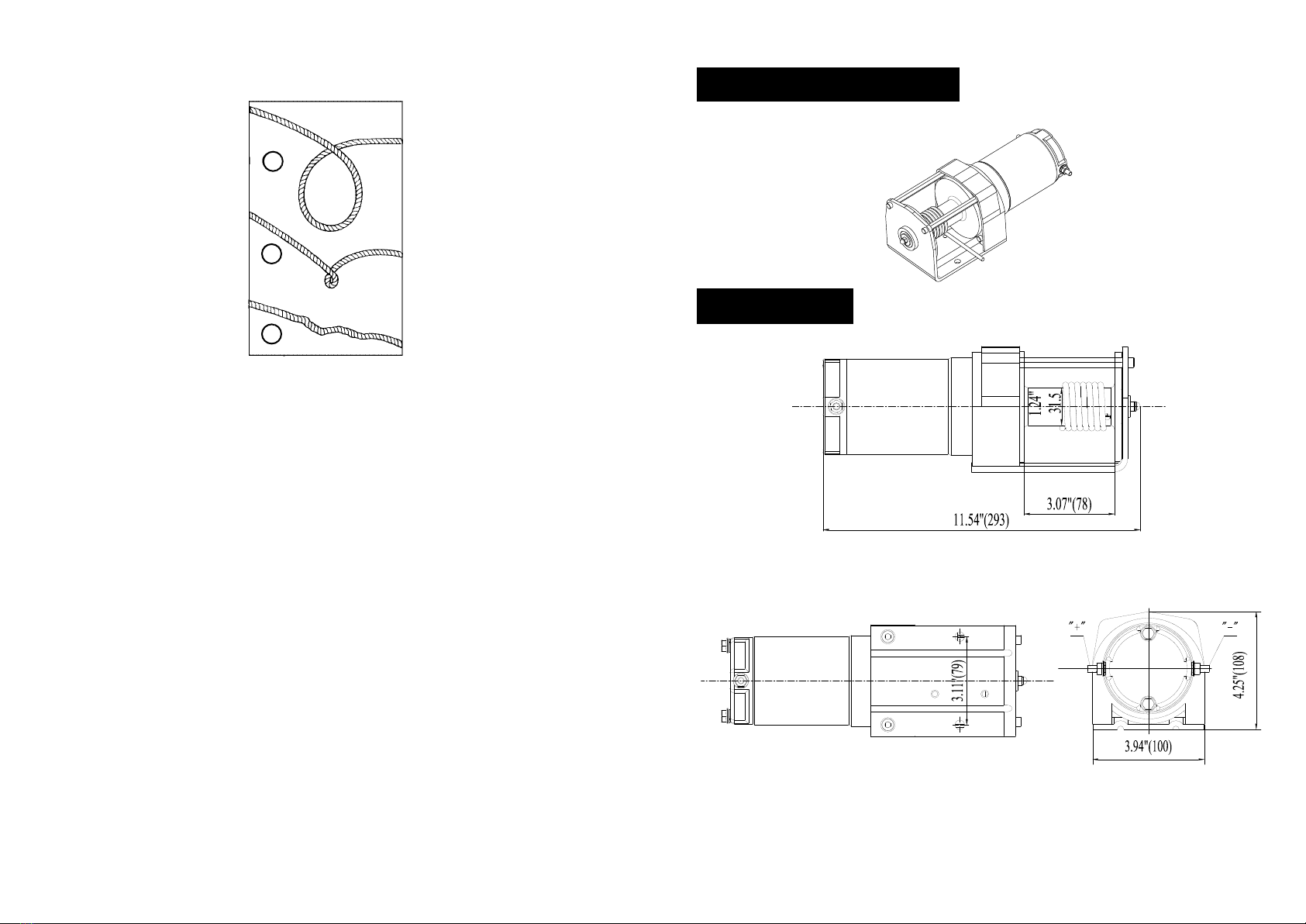
CH500
GENERAL DESCRIPTION
DIMENSIONS
Page 11
LUBRICATION
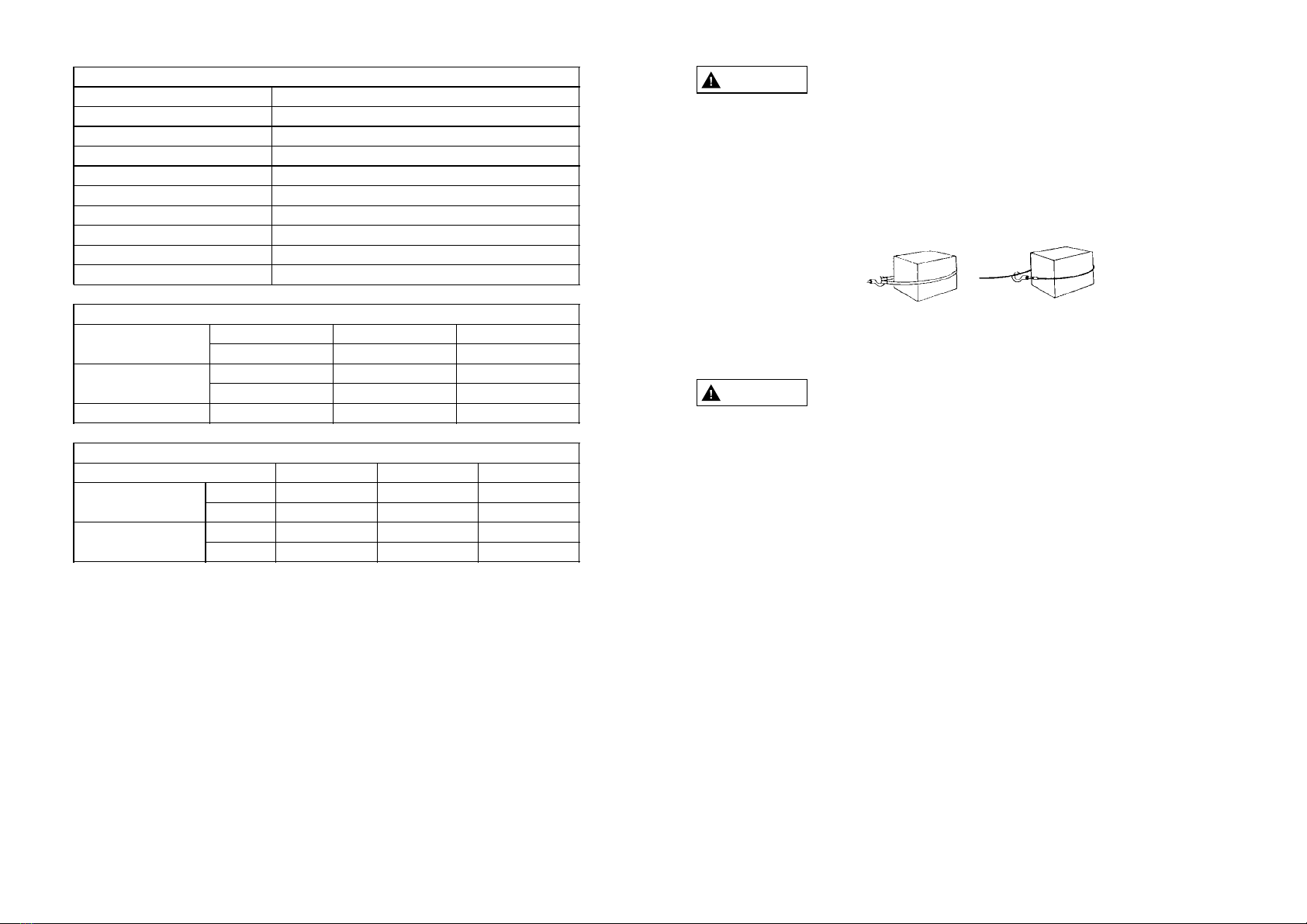
a
b
c
a. This is the start of a kink. At this time, the wire rope should best raightened.
b. The wire rope was pulled and the loop has tightened to a kink. The wire rope is now
permanently damaged and must be replaced.
c. Kinking causes the wire strands under the greatest tension to break and thus
reduces the load capacity of the wire rope. The wire rope must be replaced.
The winch is permanently lubricated. There may be grease leakage out of winch,
especially during first few operations. This is normal and it is not necessary to grease
or oil any internal part of winch at anytime.
Periodically lightly lubricate wirerope with penetration oil and wipeoff excess.
Figure 6
3. Prevent kinks before they occur. (See Figure 6)
Page 5
Line pull lbs
kgs
Line speed fpm
mpm
Motor current amps
12V DC Line speed and motor current (first layer)
0
0
11.2
3.4
18
500
226
8.2
2.5
32
Layer of cable
Rated line pull
per layer
lbs
kgs
Cable capacity
per layer
ft
m
500lb Line pull and cable capacity
12
500 395
226 180
5.5 12.4
1.7 3.8
327
148
15.7
4.8
3
Rated line pull
Motor(Series wound)
Gear train
Gear ratio
Braking action
Fairlead
Wire rope
Dimensions
Bolt pattern
Net weight
CH500lb Specifications
500lbs(226kgs)
DC 12V: 0.54hp/0.40kW
1 stage planetary gear
153:1
Differential self-locking
3/16"×15.7’(Ф4.8×4.8m)
11.81"×3.93"×4.25"(300mm×100mm×108mm)
3.12"(79.5mm)
4.7kg
4-way roller fairlead
Page 10
6. Replace wire rope when frayed.
Figure 5
Right Wrong
2.Never hook wire rope back onto itself. Hooking wire rope onto itself can damage
rope. Use a nylon sling (See Figure 5). When using a sling, make sure that sling is
properly seated in saddle of hook.
Avoid continuous pulls from extreme angles. This will cause wire rope to pile
up at one end of drum. This can jam wire rope in winch causing damage to rope
or winch itself.
3.Do not use wire rope as a ground for welding.
4.Never touch welding electrode towire rope.
5.Keep wire rope tight and even on drum.
TIPS FOR EXTENDING THE LIFE OFYOUR WINCH
1.Keep a tightly wound wire rope drum. Do not allow the wire rope to become loosely
wound. A loosely wound drum allows a wire rope under load to work its way down
into the layers of wire rope on the drum. When this happens, the wire rope maybe
come wedged within the body of the windings, damaging the wire rope. To prevent
this prob-lem, keep the wire rope tightly and evenly wound on the drum at all times.
A good practice is to rewind the wire rope under ten-sion after each use. One way to
do this is to attach the hook to as mall load and winch that load to rewind rope.
CAUTION
2. To maximize winch and wire ropelife, use pulley block to doubleline heavier loads.
Keep clear of winch wire rope and hook when operating winch. Never put your
finger through the hook. Placing finger(s) in hook could result in injury.
WARNING
Page 6Page 9
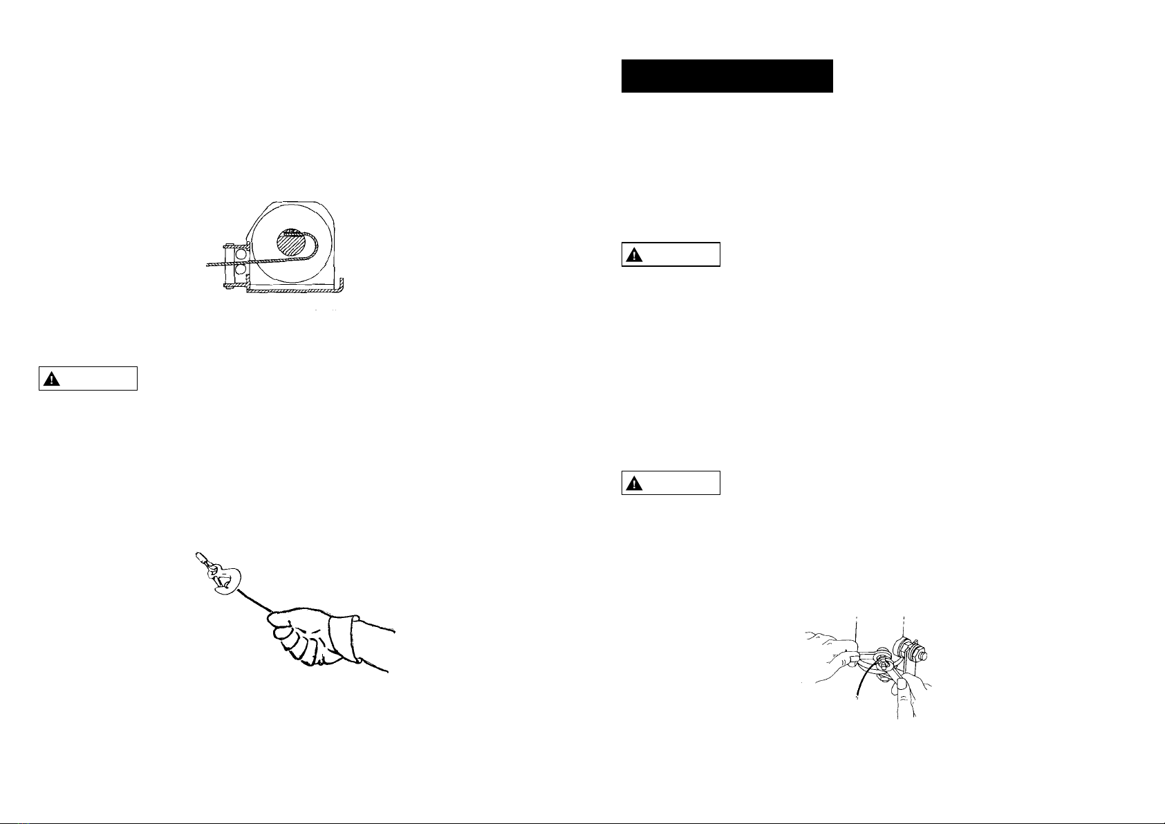
Figure 3
HANDLING THE WIRE ROPE
Use heavy leather gloves when handling wire rope. Do not allow wire rope to slide
through hands.
1.Never winch with less than 5 turns of wire rope around winch drum, since wire rope
and fasten-er may not withstand the load. Always use hand saver bar when guiding
hook for the last few feet of rope (See Figure 4)
Figure 4
WARNING
REPLACING THE WIRE ROPE
Replace damaged wire rope with the manufacturer’s recommended replacement part
or a factory approved equivalent identical in strength, quality, lay, and stranding. Pa-
ss the attaching end of wire rope through the fairlead and attach it to the drum. When
inserting the wire rope into the drum, insert it into the correct end of the hole provided
(See Figure 3). Tighten the set screw securely. It is important that the wire rope be
wound tightly onto the drum.
LOCATION
Step (1)
Step (2)
INSTALLATION
Mount the winch to a firm base. The structure the winch is attached to must be capable
of with standing a load greater than 1-1/2 times the winch′s rated line pull.
The winch can be mounted in a horizontal or vertical position. Do not mount the winch
where there would be the possibility of it being submerged in water. The winch is not
waterproof.
This winch must be mounted with the pull in the underwind direction. Improper
mounting could damage your winch, cause the brake to not work and void your
warranty.
Install structural support for winch. See "Dimensions" section for winch dimensions.
Mount the winch to the mount that you have designed. Mounting bolts supplied are the
correct length for use with a 1/4"(6.3mm) thick mounting plate.
Do not substitute any bolt with strength weaker than grade 5.
When attaching wire to the motor terminals and solenoids (relays),hold the inner nut
when tightening the outer nut. Do not allow the terminals to rotate. It may cause
internal wire breakage or part misalignment. Be especially careful in preventing the
solenoid (relay) terminals from rotating. Any rotation can damage the solenoid
(see Figure 1) .
WARNING
WARNING
Figure 1

Step (4)
Electrical Connection
Figure 2
Batteries con-tain gases which are flammable and explosive. Wear eye protection
during installation and remove all metal jewelry. Do not lean over battery while
making connections.
Select a convenient location for mounting the Control box. The mounting plate must
be electrically grounded to the battery. If it is not, the winch will not work.
There are four lengths of wire form the remote control, two red and two black. These four
wires can reach battery to the winch. (See figure 2). When routing all wires, be sure to
keep them away from all hot or moving parts.
1. Connect one of the red wire ring terminal to the motor positive terminal.
Connect one of the black wire ring terminal to the motor negative terminal.
2. Connect one of the red wire ring terminal to the battery positive terminal.
Connect one of the black wire ring terminal to the battery negative terminal.
+
-
red wire with terminal
sheathed red thermo-shrink
pipe to motor's positive stud
+
-
black wire with terminal
sheathed black thermo-shrink
pipe to motor's negative stud
red wire with terminal to
battery's positive stud
black wire with terminal
to battery's negative stud
Plug the remote control and with the directional lever in the “rope out” position,
momentarily depress the trigger to check for proper rotation direction of the winch drum.
If the winch run in the wrong direction, reverse the wires connected to the winch motor.
Page 7 Page 8
MAINTENANCE AND REPAIR
We recommend using a 15Amps circuit breaker for 24V model, 30Amp circuit breaker
for 12V model between the battery positive terminal and wire that goes to the switch
or solenoid pack. The circuit breaker prevents to overload to the switch and to the
winch motor.
Periodically check tightness of mounting bolts and electrical connections. Remove
any dirt or corrosion that may have accumulated on the electrical connections.
Circuit Breaker
Your winch has a wrap spring brake that stops and holds loads up to 500 lb. (226 kg).
When the winch is powered out, as in releasing a load, the brake is engaged and the
motor must overpower the brake resistance to rotate the drum. Therefore, it is normal
for the winch to operate faster in one direction than the other. The brake is designed
for the wire rope to be used in the unde rwind position only. Drum must turn counter-
clockwise, looking from motor end, when winching in. DO NOT OVER WIND. Powering
against the brake will cause heat to build up in the drum and may transfer heat to the
wire rope. DO NOT POWER OUT FOR MORE THAN 2 MINUTES.
The drum mayget very hot.
CAUTION
BRAKE OPERATION
OPERATION
The switch assembly must be kept free of dirt and moisture to ensure safe operation.
Do not allow winch motor to over-heat.The winch is for intermittent use only.During
long or heavey pulls the motor will get hot.Allow to cool after 2minutes of “ON” time.
PENDANT OPERATION
CAUTION
Table of contents
Other NOVAWINCH Winch manuals

Popular Winch manuals by other brands

Kolpin Outdoors
Kolpin Outdoors POLARIS SPORTSMAN Assembly & owners manual

Fransgard
Fransgard HW-3019 manual

Polestar
Polestar 12,000 user manual

WARN Works
WARN Works PullzAll user guide

Warn Industries
Warn Industries 30281 quick start guide

Champion Power Equipment
Champion Power Equipment 100776 Operator's manual


PFAFF silberblau
PFAFF silberblau DGUV V54 Translated Operating Instructions

Grizzly
Grizzly H0937 instruction manual

Harken
Harken UniPower Radial Installation and maintenance manual

TOHO
TOHO S Series instruction manual

Cequent Performance Products
Cequent Performance Products KR Series quick start guide

TRAC
TRAC T10108-25 Installation and operating instructions