Hose Reel 884 FR
Français
Manuel d’instructions
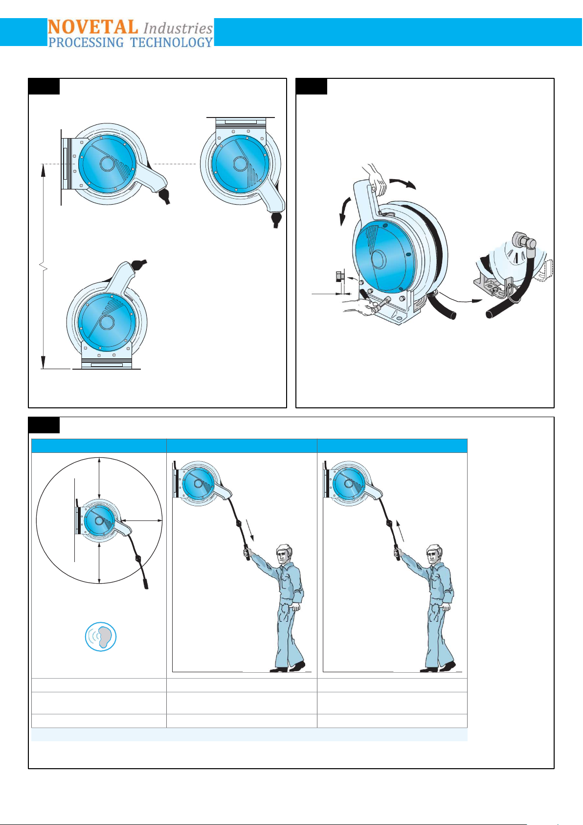
Instructions de montage (fig.1)
L´enrouleur de tuyau peut être monté au mur, au sol ou au plafond. La hauter maximum de la
position de l’enrouleur ne doit pas excéder 4 m. Choisir une surface plane sur laquelle sera
installé l’enrouleur. Utilisez le gabarit pour positionner le perçage. Assurez-vous de la solidité
des fixations. Les boulons devront tolérer un couple de torsion de 7600 N.
Tenez compte, lors du choix de l’emplacement de montage, du fait que la durée de vie du
tuyau peut être réduite s’il est exposé à des substances
chimiques et à de puissants rayonnements thermiques ou aux ultraviolets. Poids, avec
tuyau: 28 - 30kg
1
1.1 A. Bras de guidage de sortie du tuyau (fig. 2, rep A)
Le bras de guidage de sortie du tuyau peut être orienté et bloqué dans n’importe quelle position.
Choisir l’angle assurant le minimum de friction entre les galets de guidage et le tuyau.
1.2 B. Tuyau de connexion (fig. 2, rep. B)
L’enrouleur doit être raccordé aux canalisations fixes au moyen d’un flexible d’au moins 0,5 m de
longueur. Ce flexible passera à travers l’anneau* fixé sur le pied de ’enrouleur. Veillez à ce que le
flexible ne soit ni tordu ni surtendu après son montage. Un clapet d’arrêt devra être monté sur la
tuyauterie avant le raccordement du flexible.
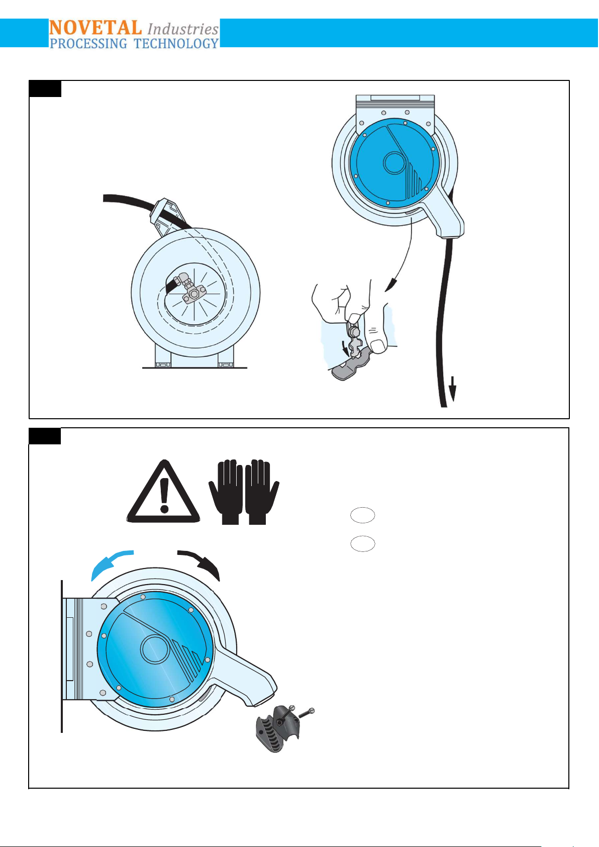
1.3 Mécanisme d’encliquetage (fig. 3)
L’enrouleur de tuyau est livré avec un mécanisme d’encliquetage qui bloque le tuyau dans la
position de déroulement désirée. L’encliquetage se libère lorsque l’on tire sur le tuyau qui
s’enroule alors sur le tambour. Tenez le tuyau avec la main jusqu’à ce quil soit complètement
enroulé.
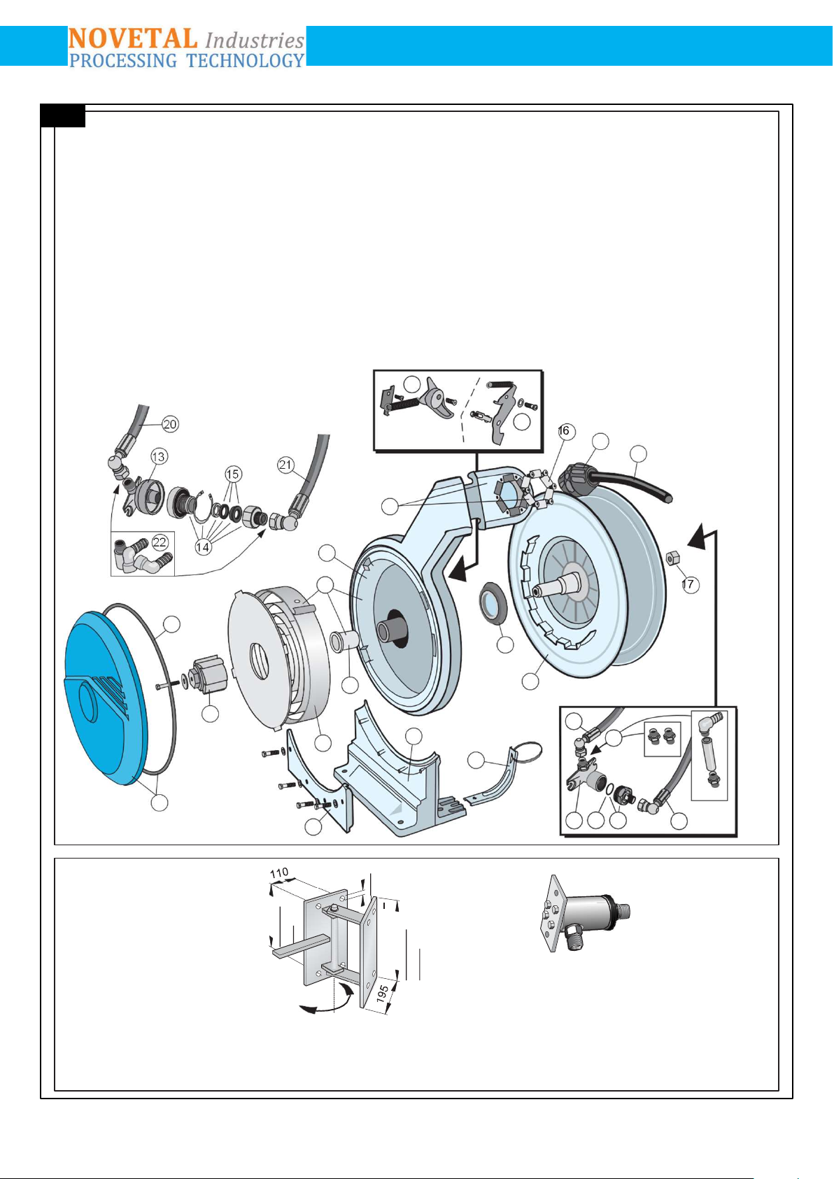
1.4 Choix dutuyau
Pour le choix du tuyau, dimensions et pression d’utilisation apparaissent sur la plaque signa-
létique de l’enrouleur. Voir aussi page 2.
AVERTISSEMENT ! Type deblessure.
L’enrouleur est équipé d’un ressort sous tension. Risque de blessure. Lire
attentivement les instructions de montage dutuyau cidessous.
1.5 Montage du tuyau (fig.4)
1. Installer l’enrouleur.
2. Passer le tuyau au travers de la sortie de tuyau de l’enrouleur, et le brancher sur le raccord
tournant. Laisser traîner le tuyau complètement déroulé sur le sol.
3. Relâcher le cran de sécurité.
4. Relâcher le mécanisme d’encliquetage en tirant le tuyau légèrementdans le sens de la flèche.
Laisser alors le tuyau s’enrouler doucement sur le tambour.
5. Fixer l’arrêtoir de tuyau.
10
NOVETAL Industrie
Tel : + 33 (0) 4 94 86 47 09 - Fax : + 33 (0) 4 94 59 32 92 E mail : info@novetal.com - Internet : www.novetal.com