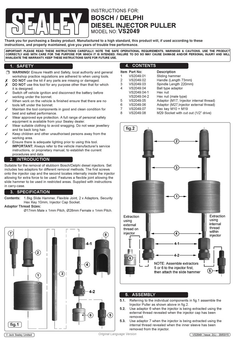
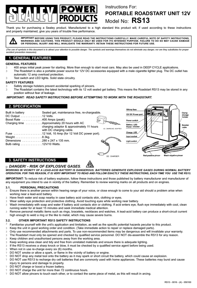
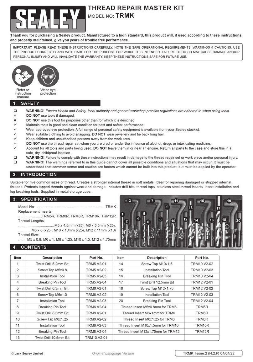
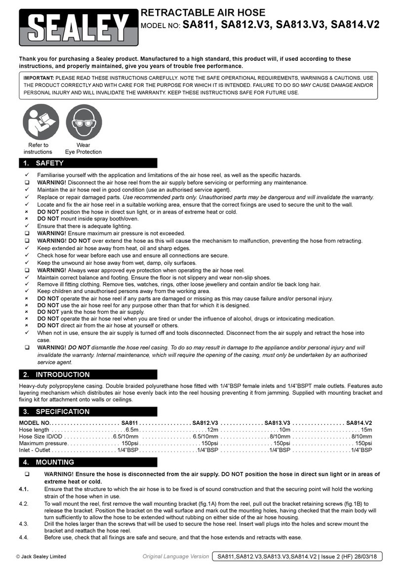
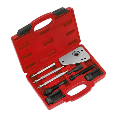
Sealey VSE135.V3 User manual

INSTRUCTIONS FOR:
PETROL ENGINE SETTING/LOCKING KIT -
BMW CHAIN DRIVE
MODEL NO: VSE135.V3
IMPORTANT: PLEASE READ THESE INSTRUCTIONS CAREFULLY. NOTE THE SAFE OPERATIONAL REQUIREMENTS, WARNINGS & CAUTIONS. USE THE PRODUCT
CORRECTLY AND WITH CARE FOR THE PURPOSE FOR WHICH IT IS INTENDED. FAILURE TO DO SO MAY CAUSE DAMAGE AND/OR PERSONAL INJURY AND WILL
INVALIDATE THE WARRANTY. KEEP THESE INSTRUCTIONS SAFE FOR FUTURE USE.
Thank you for purchasing a Sealey product. Manufactured to a high standard, this product will, if used according to these instructions
and maintained properly, give you years of trouble free performance.
1. SAFETY
2. INTRODUCTION
3. CONTENTS
WARNING! Ensure Health and Safety, local authority and general workshop practice regulations are adhered to when using tools.
DO NOT use tools if damaged.
Maintain tools in good and clean condition for best and safest performance.
Ensure that a vehicle which has been jacked up is adequately supported with axle stands.
Wear approved eye protection. A full range of personal safety equipment is available from your Sealey dealer.
Wear suitable clothing to avoid snagging. DO NOT wear jewellery and tie back long hair.
DO NOT attempt to start engine or move vehicle whilst in gear with timing devices fitted.
Always display a warning notification on steering wheel when timing engine components.
Account for all tools, locking bolts, pins and parts being used and DO NOT leave them in or near the engine.
Ensure all pieces are returned to the case and stored in a safe, dry, childproof location.
WARNING! Incorrect camshaft timing can result in contact between valve head and piston crown causing damage to the engine.
IMPORTANT: Always refer to the vehicle manufacturer’s service instructions, or a proprietary manual, to establish the current procedure and
data.
IMPORTANT: These instructions are provided as a guide only. Always refer to the vehicle manufacturer’s service instructions, or a proprietary
manual, to establish the current procedure and data.
WARNING! The warnings, cautions and instructions discussed in this manual cannot cover all possible conditions and situations that may occur.
It must be understood that common sense and caution are factors which cannot be built into this product, but must be applied by the operator.
Refer to
Instructions
Wear Eye
Protection
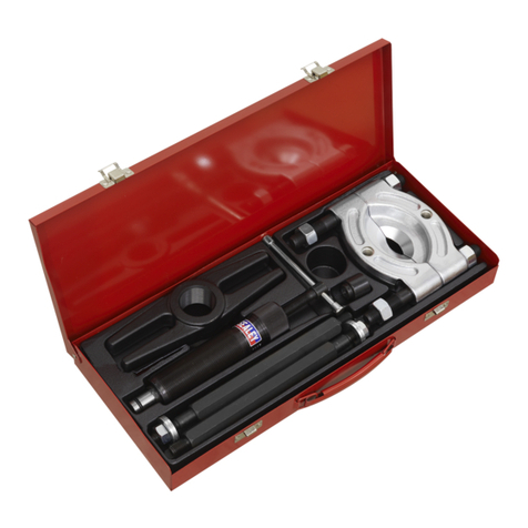
Wide ranging kit for BMW engines. Iincludes tools for setting and locking camshafts and also tools for setting up timing chain tension.
Item: Part No: Description: VM Part No:
1 VSE135.V3-01 Camshaft Alignment Tool 11 3 390
2 VSE135.V3-02 Flywheel Locking Pin 11 2 300
3 VSE135.V2-01 LH Camshaft Locking Plate 11 3 241
4 VSE135.V2-02 RH Camshaft Locking Plate 11 3 242
5 VSE135.V2-03 Camshaft Locking Plate Joint 11 3 244
6 VSE135.V2-05 M8 Screw
7 VSE135.V2-07 Tensioner Locking Pin 11 4 120
8 VSE135.V2-10 M8 Hex Head Screw P1.5x30
9 VSE135.V2-11 Block Inlet 5-8 11 2 442
10 VSE135.V2-12 Block Inlet 1-4 11 2
11 VSE135.V2-13 Block Exhaust 1-4 11 2 445
12 VSE135.V2-14 Block Exhaust 5-8 11 2 446
13 VSE135.V3.07 Timing Chain Tensioner 11 3 390
VSE135.V3 Issue:2(I) - 26/02/15
© Jack Sealey Limited Original Language Version

5.1. This kit has the necessary tools to set and lock the engines on a wide variety of BMW vehicles ranging from 1.6 to 5.0 litres in size. As there
will be many variations on these applications, these instructions have been produced as a guide only to the most popular applications.
For further and more detailed information, the use of a manufacturers or a suitable proprietary manual is strongly advised.
5.2. M40 and M70 Engines
5.2.1. Position the engine at TDC on number one cylinder. Insert the Crankshaft Timing Pin VSE135.V3-02 through the datum hole in the cylinder
blockandensureitcorrectlylocatesintothelocationholeintheywheel(g.1)
5.2.2. FittheCamshaftAlignmentPlateVSE135.V3-01ontothesquaredareofthecamshaftasshown(g.2). Ensurethecamshaftsprocket
arrow is pointing upright, (12 o’clock position)
5.2.3. Press the timing chain tensioner rail in to compress the tensioner and insert a suitable locking pin.
5.2.4. Any engine work required can now be carried out, once completed, reassemble the engine as required and remove the tooling, rotate the
crankshaft through two revolutions and recheck the timing using the Crankshaft Timing Pin VSE135.V3-02 and Camshaft Alignment Plate
VSE135.V3-01 as previously described. Once the timing is set correctly, remove all tooling and reassemble the engine in the reverse order of
dismantling.
5.3. M42 and M50 Engines
5.3.1. Dismantling:
Turn the engine in the direction of rotation and insert the Crankshaft Timing Pin VSE135.V3-02 through the datum hole in the bell housing.
(g.1)
5.3.2. To ensure the engine is correctly positioned at TDC check that the camshaft lobes on number one cylinder are almost facing each
otherasshown(g.3)
Models: Engines: Associated Tools: Description: VM Tool Ref:
BMW 1.6 VSE5906 Petrol Twin Vanos Service Tool Kit - Chain Drive 11 6 150
316i 1.6 E36 (93-99) 16 4E 2 11 3 450
316i Compact 1.6 E36 (94-00) 16 4E 3 11 6 180
318i 1.8 E36 (94-99) 1.8
318iS 1.8 E36 (92-98) 18 4E 2
318i Compact 1.8 E36 (94-98) 18 4S 1
316i Compact 1.9 E36 (98-01) 1.9
318iS 1.9 E36 (96-99) 19 4E 1
318i Compact 1.9 E36 (96-01) 19 4S 1
320i 2.0 E36 (94-99) 2.0
323i 2.5 E36 (95-99) 20 6S 3
323i Compact 2.5 E36 (95-01) 2.0
328i 2.8 (95-99) 20 6S 3
316i 1.6 E46 (99-01) 2.8
316i 1.9 (99-02) 28 6S 1
318i 1.9 (98-01) 3.5
520i 2.0 E39 (96-00) 35 8S 1
523i 2.5 E39 (96-00) 4.0
528i 2.8 E39 (96-00) 40 8S 1
535i 3.5 E39(96-01) 4.4
540i 4.4 E39 (96-03) 44 8S 1
Z3 1.8 E36 (96-99) 5.0
Z3 1.9 E36 (96-03) 50 12 A
Z3 2.8 E36 (97-99) 5.4
840i 4.0 E31 (93-99) 54 12 1
840i 4.4 E31(95-99) 54 12 2
850i 5.0 E31 (90-99)
4. APPLICATIONS
5. INSTRUCTIONS
fig.1ifig.2
VSE135.V3 Issue:2(I) - 26/02/15
© Jack Sealey Limited Original Language Version

fig.3 fig.4
5.3.3. FittheCamshaftLockingPlateVSE135.V2-01/VSE135.V2-02(g.4).
5.3.4. Slackentheexhaustcamshaftsprocketxingbolts.
5.3.5. Compress the secondary timing chain tensioner and lock it in its retracted position using a suitable pin.
5.3.6. Oninletcamshaftdrivesprocketswithoutaspringplatetted,removetheVanosunit,thecamshaftsprocketxingnutsandthethrust
washer.
5.3.7. Oninletcamshaftdrivesprocketsthatdonothaveaspringplatetted,removetheVanosunitwhileturningtheexhaustcamshaftsprocket
inaclockwisedirection.Removethecamshaftsprocketxingnutsandthespringplate.
5.3.8. It is now possible to remove the timing chain, sprockets, guides and tensioners.
WARNING: The tensioner has a very strong spring.
5.4. Reassembly
5.4.1. Fit the camshaft drive sprocket, ensure the arrow is pointing upwards and that the threaded holes are positioned on the left side of the slots
inthesprocket(g.5).
5.4.2. Fit the Timing Chain Pre-tensioning tool VSE135.V3-07 and screw the adjuster in until
it comes into contact with the guide rail; do not tighten further past this point.
5.4.3. Fit the timing chain guide and secondary timing chain tensioner.
5.4.4. Fit the secondary timing chain and sprocket; ensure that the threaded holes are
positioned on the left side of the slots in the sprocket.
5.4.4. Fitthethrustwashers,andspringplate,totheinletcamshaftandtightenthexingnuts
to 10Nm
5.4.5 On inlet camshaft sprockets that do not have a spring plate, turn the sprocket clockwise
until the detent position is reached.
5.4.6. Turn the sprocket ant-clockwise whilst inserting the Vanos unit, turn the splined shaft
until it engages.
5.4.7 On inlet camshaft sprockets without the spring plate, turn the sprocket clockwise as far
as the stop.
5.4.8. Turnthesprocketanti-clockwisewhilstinsertingtheVanosunituntiltheunittsush
with the cylinder head.
5.4.8. Tighten the Vanos unit securing bolts.
5.4.9. Remove the locking pin from the secondary timing chain tensioner.
5.4.10. Preload the timing chain by tightening the Timing Chain Pre-tensioning tool
VSE135.V3-07 to 1.3 Nm.
5.4.11. Tighten the exhaust camshaft sprocket securing bolts initially to 1.5Nm followed by 2.22 Nm.
5.4.12 Removethetimingchainpre-tensionerandretthetimingchaintensioner.
5.4.13 Remove all tooling, turn the crankshaft through two revolutions clockwise. Ensure the Crankshaft Timing Pin VSE135.V3-02 and the
CamshaftLockingPlateVSE135.V2-01/VSE135.V2-02canberetted.
5.4.13. Oncethetimingisconrmedascorrect,removealltoolingandreassembletheengineinthereverseorderofdismantling.
5.5. M60 and M62 Engines
5.5.1. Note: To remove the timing chain on these engines the sump will need to be removed.
This kit does not contain the tooling to set the camshaft sensor plate positions if the
engineissotted.
5.5.2. If the transfer chains need to be removed, their tensioners will need to be locked in their
retracted position using suitable tensioner locking pins.
5.5.3. Dismantling
Turn the engine in the direction of rotation and insert the appropriate Crankshaft Timing
PinVSE135.V3-02throughthedatumholeinthebellhousing(g.1).
5.5.4. There is a stamped mark on the lower timing case "OT" that must match up with the
same mark on the crankshaft pulley "OT".
(DO NOT use the 45 .VOT marking on the pulley).
5.5.5. To ensure the engine is correctly positioned at TDC check that the camshaft lobes on
numberonecylinderarealmostfacingeachotherasshown(g.6)
5.5.6. Oncetheengineiscorrectlypositionedthecamshaftlockingtoolscanbetted.
fig.5
fig.6
VSE135.V3 Issue:2(I) - 26/02/15
© Jack Sealey Limited Original Language Version

5.5.7. The Camshaft Locking Tools are a paired set, one pair is machined for each bank
of cylinders.
5.5.8. The Camshaft Locking Tools interlock and bolt together and are paired with each
other, each pair must only be used with its matching half.
5.5.9. The camshafts do have provision to allow them to be turned using a 27mm open
ended spanner, this feature should NOT be used to attempt to rotate the engine.
5.5.10. The intake cam is referred to as the E cam and the exhaust cam is referred to as
the A cam.
5.5.11. For the right hand bank (Cylinders 1 to 4) use the Camshaft Locking Tools
VSE135.V2-12/VSE135.V2-13. For the left hand bank use the Camshaft Locking
Tools VSE135.V2-11/VSE135.V2-14.
5.5.12. Thekit’sCamshaftLockingToolstoverthesquaredareasattherearendofthe
camshafts.
5.5.13. The Camshaft Locking Tools lock the camshafts together, after positioning over the
camshaftsensurethetoolingsitsushagainstthecylinderhead(g.7).
5.5.14. With the engine now set and locked into position; the timing chain and sprockets
can be removed.
5.6. Reassembly
5.6.1. Before re-assembly work commences, the timing chain tensioner will need to be
removed;thisislocatedontherighthandbank(g.8).
5.6.2. Retthetimingchainandsprockets,ensurethethreadedholesareinthecentre
of the slots in the sprockets, do not fully tension the securing bolts. Ensure the
sensorgearmarkisinthe11o’clockposition(g.5).
5.6.3. Fit the secondary tensioners and guide rails, release the secondary tensioners from
their locked position.
5.6.4. Once the timing chain has been installed, the timing chain pre-tension needs to be
set; it is important to use this method to pre-tension the timing chain, and not to
rely on the engine’s normal tensioner system as this tensioning method would not
be accurate enough.
5.6.5. Fit the VSE135.V3-07 assembly in place of the timing chain tensioner, and tighten
the centre bolt to 0.7Nm.
5.6.6. Tighten the camshaft sprocket bolts.
5.6.7. RemovetheVSE135.V3-07assemblyandretthetimingchaintensioner.
5.6.8. Remove all tooling, turn the crankshaft through two revolutions clockwise and
recheck the timing.
5.6.9. Oncethetiminghasbeenconrmedascorrect,removethetoolingandreassemble
the engine in the reverse order from that used to dismantle.
fig.7
fig.8
Environmental Protection
Recycle unwanted materials instead of disposing of them as waste. All tools, accessories and packaging should be sorted, taken to a recycling centre
and disposed of in a manner which is compatible with the environment. When the product becomes completely unserviceable dispose of it according to
local regulations.
NOTE: It is our policy to continually improve products and as such we reserve the right to alter data, specifications and component parts without prior notice.
IMPORTANT: No liability is accepted for incorrect use of this product.
WARRANTY: Guarantee is 12 months from purchase date, proof of which will be required for any claim.
01284 757500
01284 703534
sales@sealey.co.uk
Sole UK Distributor, Sealey Group,
Kempson Way, Suffolk Business Park,
Bury St. Edmunds, Suffolk,
IP32 7AR
www.sealey.co.uk
VSE135.V3 Issue:2(I) - 26/02/15
© Jack Sealey Limited Original Language Version

Other Sealey Tools manuals

Sealey
Sealey gh60 User manual

Sealey
Sealey VS819900 User manual

Sealey
Sealey ATD25301 User manual

Sealey
Sealey SMS7P User manual

Sealey
Sealey AB932.V4 User manual

Sealey
Sealey RE97XS05 User manual

Sealey
Sealey VSE5586 User manual

Sealey
Sealey SA88.V3 User manual

Sealey
Sealey VS312 User manual

Sealey
Sealey VS9111 User manual

Sealey
Sealey SA811 User manual

Sealey
Sealey VS722.V3 User manual

Sealey
Sealey Auto Service VSE4780.V2 User manual

Sealey
Sealey VS0110 User manual

Sealey
Sealey SA120.V2 User manual

Sealey
Sealey AK9622EV User manual

Sealey
Sealey WORKSAFE 9602L User manual

Sealey
Sealey AK467D User manual

Sealey
Sealey CP20VPSH User manual

Sealey
Sealey HRCHD User manual