Novinium 260 User manual

©Novinium, Inc. 2019, all rights reserved. Novinium, Inc.
engineering@novinium.com 22820 Russell Rd Kent, WA 98032
Revised: December 27, 2019 (253) 395-0200
Rejuvenation Instructions
#260 –TDR Diagnosis
This NRI covers the following:
•How to use Impedance Transition Device (ITD) Streamliners.
•How to use the time domain reflectometer (TDR) for the 1205CXA Model family.
Trademarks: http://www.novinium.com/trademarks/
Patents: http://www.novinium.com/patents/
WARNING: It is dangerous working around energized high-voltage systems,
pressurized systems, and chemicals. Always work in accordance to the
Novinium Field Operations Safety Handbook (FOSH) or other local governing
safety standards.

©Novinium, Inc. 2019, all rights reserved. NRI 260 –TDR Diagnosis
Revised: December 27, 2019 Page 2of 20
Table of Contents
TDR Recommended Settings................................................................................................................................................... 3
Making an Electrical Connection.............................................................................................................................................4
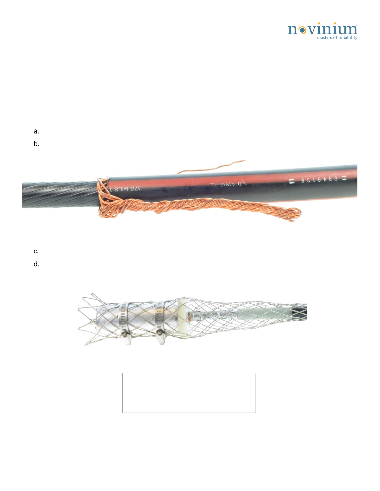
Connecting to URD cables...................................................................................................................................................4
Using alligator clips .............................................................................................................................................................5
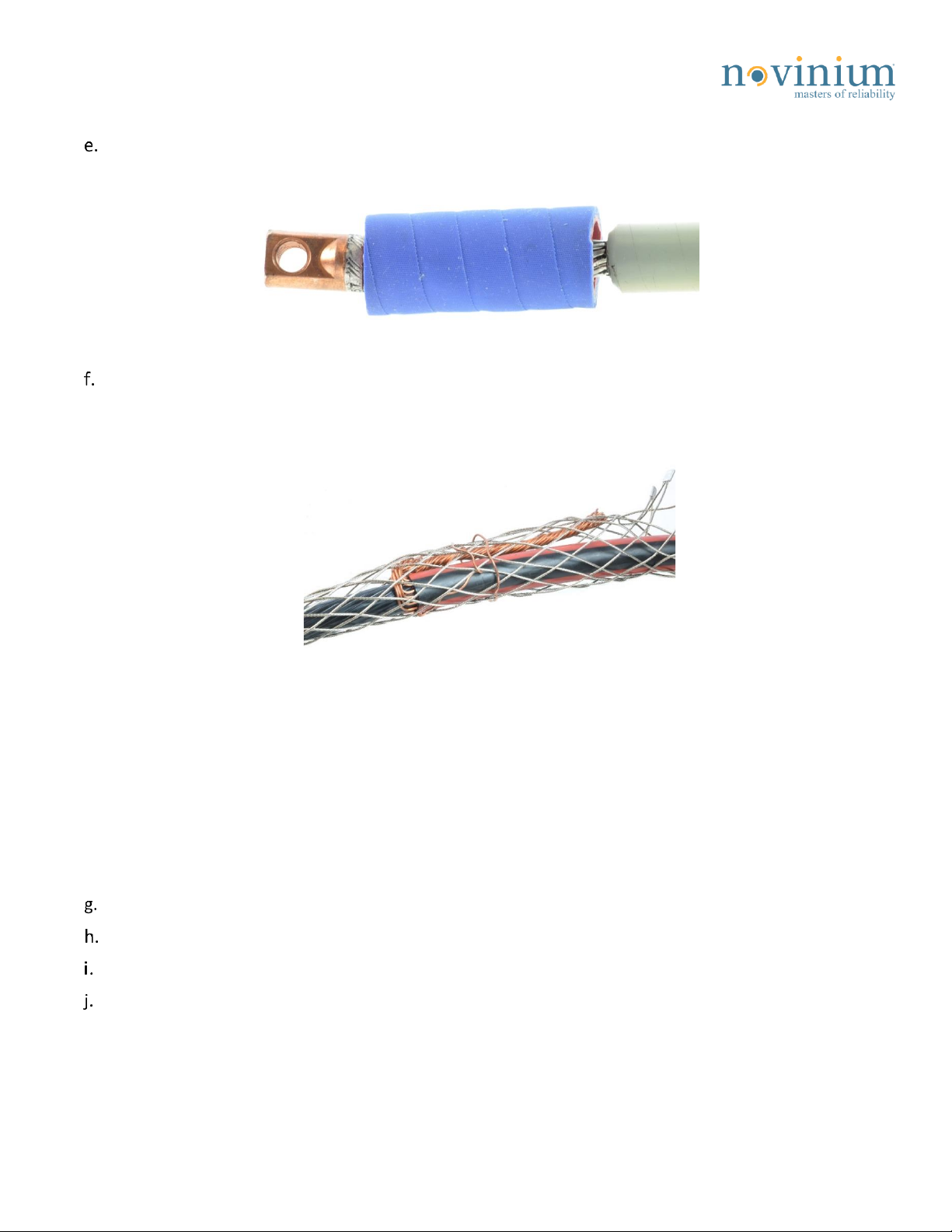
Connecting cables with paddle connectors........................................................................................................................6
Connecting feeder cables without connectors...................................................................................................................7
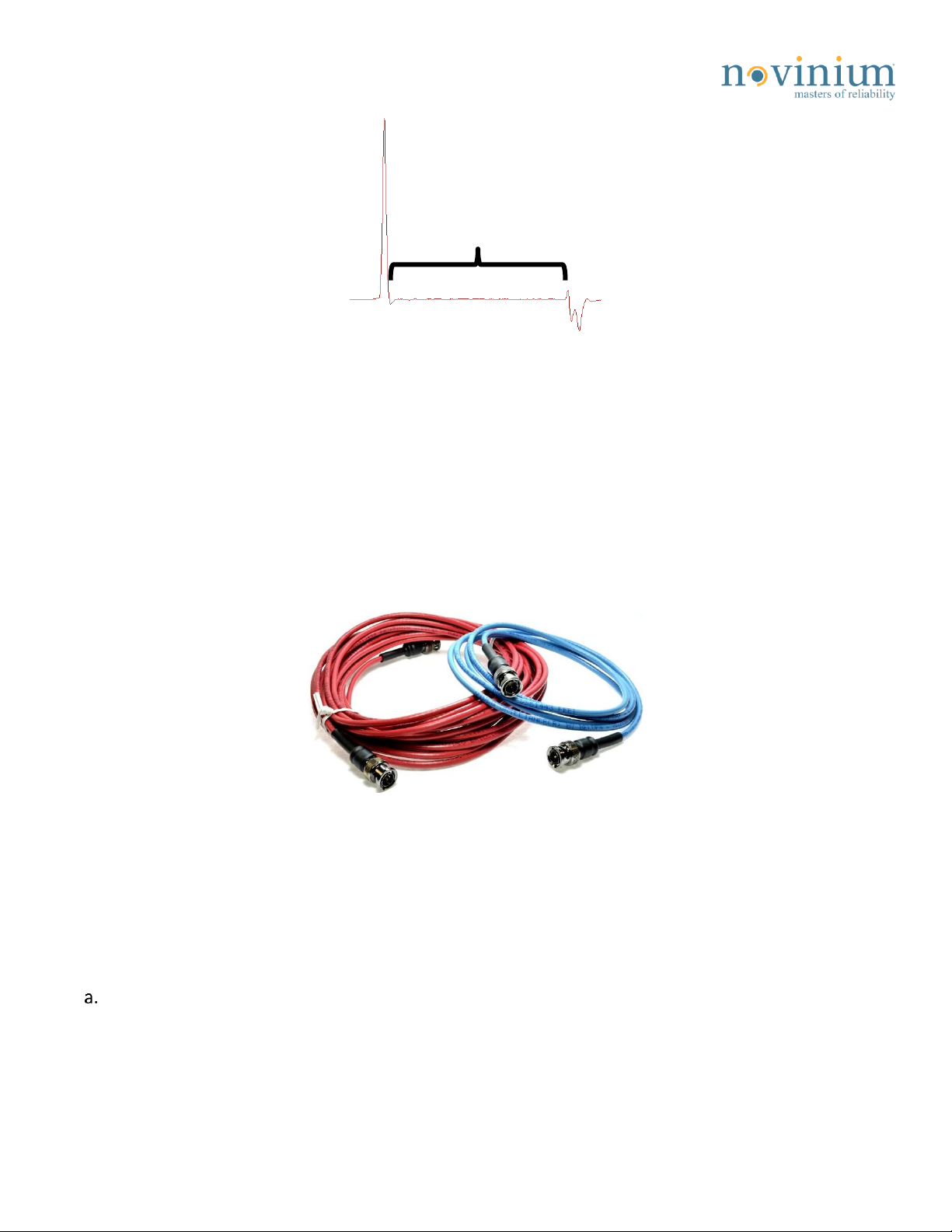
Select a Lead Cable .................................................................................................................................................................7
Checking TDR Settings.............................................................................................................................................................8
1. Startup settings.....................................................................................................................................................8
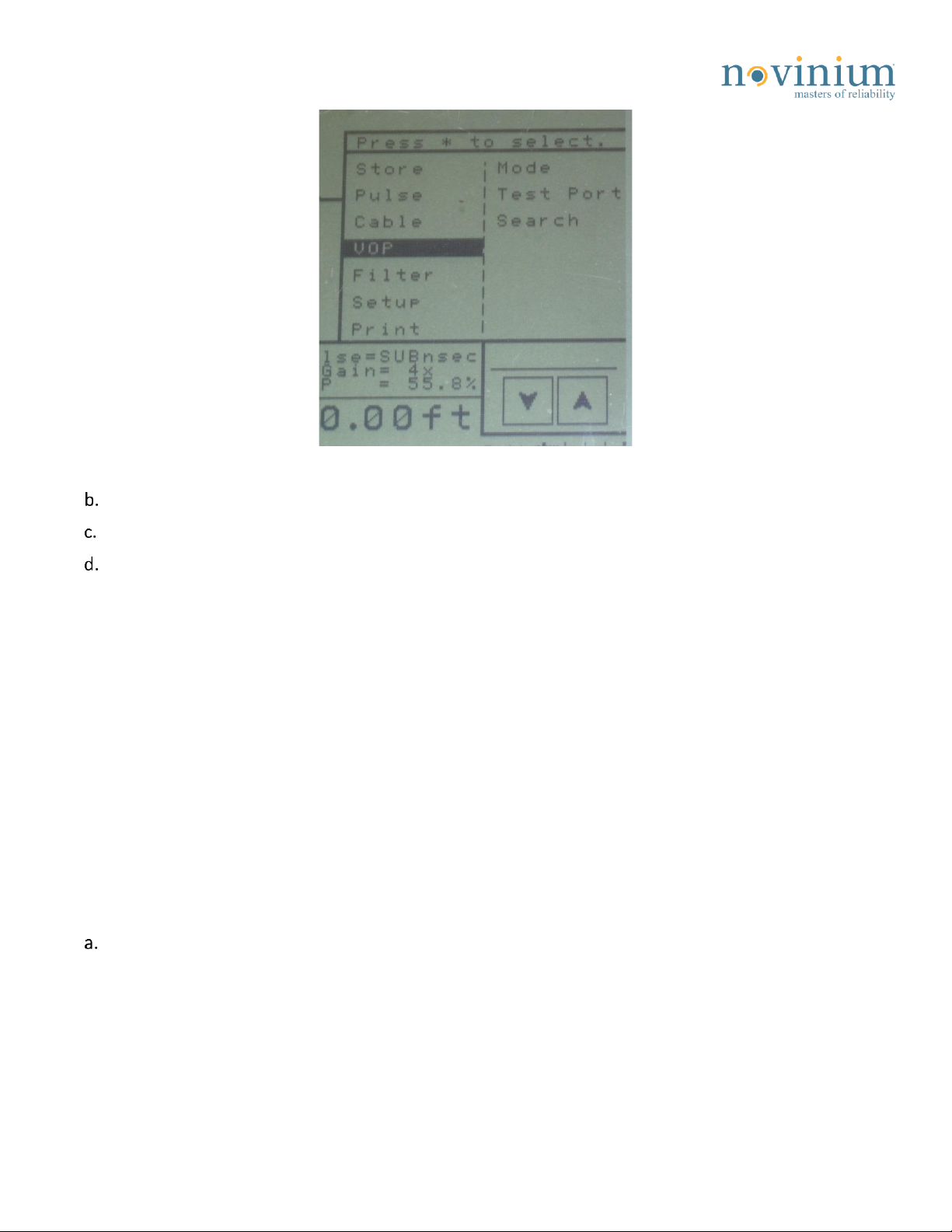
Calibrating the Velocity of Propagation (VOP)........................................................................................................................9
1. Initial VOP..............................................................................................................................................................9
2. Confirm the VOP. .................................................................................................................................................. 9
Analyzing the TDR .................................................................................................................................................................10
1. Consistency is key. ..............................................................................................................................................10
2. Find the beginning of the cable. .........................................................................................................................10
3. Find the end of the cable. ...................................................................................................................................12
4. Identify anomalies...............................................................................................................................................13
5. Measure the distances of anomalies. .................................................................................................................16
6. Swap cable leads.................................................................................................................................................17
TDR from Termination 2 .......................................................................................................................................................17
Signal Strength......................................................................................................................................................................18
Saving the Waveform............................................................................................................................................................18
Tips and Troubleshooting .....................................................................................................................................................19
1. Two measurement rule.......................................................................................................................................19

©Novinium, Inc. 2019, all rights reserved. NRI 260 –TDR Diagnosis
Revised: December 27, 2019 Page 3of 20
TDR Recommended Settings
•Access the setup option through the TDR’s menu.
TDR Recommended Settings
Horizontal scale units
FEET (set to Meters if preferred)
Distance display format
FEET (set to Meters if preferred)
Horizontal reference
ON
Backlight at startup
OFF (set to ON for nighttime work)
Velocity format
VOP (%)
VOP precision
3 DIGIT
Cancel test lead length
NO
Serial printer type
CITIZEN
Memory options
16 WAVEFORMS (saves most data per trace)
Autofilter
DISABLED
dBRL type
TOTAL
Language
ENGLISH
•Choose the option to EXIT after setup is complete.
TDR Quick Tips (Basic Operation):
Use an ITD Streamliner whenever possible.
•Set the Pulsewidth to 2ns.
•Set vertical gain at 8-10X.
•Check that VOP is correct (typically 48-55%).
•Set the first cursor at the beginning of the cable.
•Zoom out –Center the picture.
•Zoom in at the end of the cable –place the second cursor at the far end of the cable.
•Avoid using radios and cell phones while examining the cable.
•Use filters to reduce noise if needed.
•Set contrast only as high as needed.
•Use clips supplied with TDR if the ITD Streamliner is not possible.
•Use 25ns or 100ns pulse width for long cables where the far end cannot be seen.

©Novinium, Inc. 2019, all rights reserved. NRI 260 –TDR Diagnosis
Revised: December 27, 2019 Page 4of 20
Making an Electrical Connection
•All waveforms uploaded to Knomentous should be taken with an ITD Streamliner if injected. This gives a
cleaner waveform than the alligator clips.
•The ITD Streamliner should be used unless the situation prevents it.
•Notate any uploaded waveforms taken with the alligator clips in the Knomentous comments.
Connecting to URD cables.
Remove the cable accessory as necessary to allow a connection.
Wrap or twist the neutral wires along the cable to minimize the separation between the conductor and
neutral.
Figure 1: Winding the neutrals together can help minimize separation to the conductor.
Clean the neutral wires for a good connection.
Slip the Kellems grip and ITD Streamliner over the end of the cable until the inner conductor cone
contacts the end of the compression connector.
Figure 2: ITD Streamliner on the connector.
Note: If there is not enough concentric
neutral to reach the Kellems grip, wrap
neutrals upward toward the connector.

©Novinium, Inc. 2019, all rights reserved. NRI 260 –TDR Diagnosis
Revised: December 27, 2019 Page 5of 20
The Kellems grip should not make electrical contact with any conductor which would cause a short.
•Placing an insulating sleeve or cover over the connector can help prevent contact.
Figure 3: An insulating cover over the connector will prevent shorts to the Kellems grip.
Ensure good electrical contact between:
•The ITD Streamliner conductor cone and the connector.
•The Kellems grip, ITD Streamliner body, and the cable’s neutrals.
Figure 4: The ITD Streamliner’s Kellems grip in good contact with the neutral wires.
Wrapping a single wire around the Kellems grip as (see Figure 4) will help hold the ITD Streamliner in place.
Using alligator clips
The alligator clips supplied with the TDR provide less clear signal than the ITD Streamliner. Clips may only
be used as an electrical connection if:
•iUPR injection elbows have already been installed.
•For preliminary diagnosis such as choosing between the SPR and iUPR process.
Attach a probe wrench to the elbow probe.
Connect one of the alligator clips to the metallic body of the probe wrench.
Connect the other clip to the cable neutrals.
Make sure that the clip connected to the neutrals does not make electrical contact with the conductor
or any connections that do.

©Novinium, Inc. 2019, all rights reserved. NRI 260 –TDR Diagnosis
Revised: December 27, 2019 Page 6of 20
Figure 5: Alligator clips.
Connecting cables with paddle connectors.
a. Follow steps a-c in the URD cable section to prepare neutrals
b. Connect the ITD Streamliner to the connector.
•Depending on cable size, this will be done by attaching the alligator clip or clamping the paddle
with the bolt.
Figure 6: ITD attachment for URD cables.
•For feeder cables, use the alligator clip to clamp onto the connector.
Figure 7: Using the alligator clip to clamp onto the connector of a feeder cable.

©Novinium, Inc. 2019, all rights reserved. NRI 260 –TDR Diagnosis
Revised: December 27, 2019 Page 7of 20
Connecting feeder cables without connectors
Drive a small nail or screw into the end of the conductor to provide a contact point.
Connect the nail or screw to the ITD Streamliner, depending on the ITD Streamliner type.
•Feed the nail into the cone of the URD ITD Streamliner
Figure 8: Using a nail or screw to make a connection with the ITD Streamliner.
•Unscrew the feeder ITD Streamliner’s paddle and rod and place the nail into the threaded hole.
Figure 9: Unscrew the paddle and rod Figure 10: Insert the nail into the ITD Streamliner
•Clamp the alligator clip of the feeder ITD Streamliner to the nail.
Figure 11: Using the alligator clip to clamp onto the nail.
Follow steps d-f of the URD cable section
Select a Lead Cable
The lead cable connects the ITD Streamliner to the TDR.
On the waveform, the length between the TDR pulse and ITD Streamliner signature is the lead cable. The
length displayed on the wave is the actual length of the lead cable used.

©Novinium, Inc. 2019, all rights reserved. NRI 260 –TDR Diagnosis
Revised: December 27, 2019 Page 8of 20
Figure 12: The lead cable between the TDR pulse and ITD Streamliner.
Different lead cable lengths are available for use, each having its strengths and weaknesses.
Select a lead cable based upon the current goal of the TDR analysis.
The longest lead cable will:
oStore the cleanest waveform with a minimum of echoes.
oShow cable anomalies more clearly within the first 20 feet from a termination.
The shorter lead cable will decrease the distance between the ITD Streamliner and the TDR, leading to more
echoes in the waveform. However, if you are unsure of a waveform, it is good practice to change lead cables
to verify cable anomalies.
Figure 13: 30ft (Red) and 6ft (Blue) lead cables.
After selecting a lead cable, connect the cable to the top of the ITD Streamliner and to the TDR.
•Bending the wires can cause internal damage and malfunction.
Checking TDR Settings
1. Startup settings.
Press the “Star” button above the two blank soft key buttons to bring up the TDR function menu.
Lead Cable

©Novinium, Inc. 2019, all rights reserved. NRI 260 –TDR Diagnosis
Revised: December 27, 2019 Page 9of 20
Figure 14: Star menu.
Select “Pulse” and choose the “2ns” setting.
Use the Vertical Gain buttons to set the gain initially between 8x and 10x.
See the quick tips and settings section at the end of this NRI for more detailed startup instructions.
A laminated card with the tips and settings is also supplied with each TDR
Calibrating the Velocity of Propagation (VOP)
1. Initial VOP.
•To start, locate the cable run and make a wheeled measurement to find VOP. The VOP is the
speed at which the TDR pulse travels through the cable.
•Depending on the insulation, the VOP for power cables generally ranges from 48% to 55% of the
speed of light. However, cables can have higher or lower VOPs due to factors like the type, age,
and condition of the insulation.
•A cable’s VOP can vary by insulation type, neutral type, neutral corrosion, and many other factors.
It is important to confirm VOP regularly using the guide below.
2. Confirm the VOP.
Confirm the VOP value by making a wheeled measurement (or equivalent) of the cable path. This
should be done:
•At least once each day.
•Each time a new loop is started.
•Each time a splice needs pinpointing.
•When encountering a different cable type.

©Novinium, Inc. 2019, all rights reserved. NRI 260 –TDR Diagnosis
Revised: December 27, 2019 Page 10 of 20
It is not necessary to re-confirm the VOP for each cable in other cases.
•Adjacent runs of similar cables with significantly different VOPs may signal a deviated cable path.
•Confirm with the RF Locator as described in NRI 270.
Place the cursors at the beginning and end of the cable.
Adjust the VOP on the TDR until the length displayed equals the wheeled length.
•The VOP is now calibrated for this cable type.
Analyzing the TDR
1. Consistency is key.
It is important to keep consistent TDR methods and watch for differences in the wave between cables.
Keep these in mind:
•Cable types are usually the same from segment to segment.
•The TDR will function similarly each time.
•ITD Streamliners will function and appear similarly on the TDR each time.
Use consistency as an advantage. Remember the characteristic shape of the ITD Streamliner.
•Noticeable differences to the ITD Streamliner shape on the wave can signify a connection issue or
the presence of an anomaly.
2. Find the beginning of the cable.
The initial large positive spike on the wave is the pulse created by the TDR.
Figure 15: The initial TDR pulse.
Look for the “W” shape near the beginning of the waveform. This is the signature of the ITD
Streamliner connected to the end of the cable.

©Novinium, Inc. 2019, all rights reserved. NRI 260 –TDR Diagnosis
Revised: December 27, 2019 Page 11 of 20
Figure 16: The ITD Streamliner signature.
Create a short on the waveform at the ITD Streamliner by connecting a short jumper wire or
screwdriver between the Kellems grip to the connector/conductor. Squeezing the Kellems grip against
the connector works as well.
Figure 17: Use a screwdriver or squeeze to create a short between the Kellems grip and connector.
•The left edge of the “W” shape should become a large down spike.
•Connecting the neutrals to the connector creates the same short.
•Shorts are large negative spikes on the waveform.
Figure 18: A short between the Kellems grip and connector shown on the waveform as a negative spike.

©Novinium, Inc. 2019, all rights reserved. NRI 260 –TDR Diagnosis
Revised: December 27, 2019 Page 12 of 20
Alternate connecting and disconnecting.
•A large negative spike should appear and disappear on the wave.
Place Cursor 1 where the negative spike begins. This is the beginning of the cable (term 1).
Remove the short, and return the ITD Streamliner signal to normal.
Figure 19:The cursor location after the short is removed.
After becoming proficient in locating the ITD Streamliner based on its signature, connecting the
Kellems grip to the connector/conductor isn’t necessary.
3. Find the end of the cable.
Zoom out until the far grounded end of the cable (term 2) is clearly visible.
•If the end is not visible, increase the pulse width to 25ns or 100ns.
•Always set the pulse width to the lowest value that can detect the grounded cable end.
“Bump Ground” by disconnecting and reconnecting the ground at term 2.
•Bumping ground helps identify the cable end by an impedance reflection.
Figure 20: What bumping ground does to the wave.
Ignore reflections at distances which are multiples of the lead cable and anomalies.
If the TDR wave does not respond appropriately, investigate the cause before continuing.
Cable open
Cable shorted

©Novinium, Inc. 2019, all rights reserved. NRI 260 –TDR Diagnosis
Revised: December 27, 2019 Page 13 of 20
•A TDR wave not responding to a ground connection and
disconnection may indicate a bad connection or that the wrong
cable is being disconnected!
•Confirm that the cable is correct before proceeding.
•WARNING: Improper cable identification can lead to severe injury or
death!
Zoom in on the end of the cable.
Bump ground and look for the point where the signal begins changing from negative (when grounded)
to positive (when ungrounded).
Place Cursor 2 where the ground signal begins to drop. This is the end of the cable (term 2).
Record the cable length and the VOP used.
4. Identify anomalies.
•Identify each impedance anomaly in the cable.
•Closely examine the first and last 20 feet of the cable. Echoes and large pulses can hide anomalies.
•The following items are common anomalies with a description for each.
ITD Streamliners:
•The ITD Streamliner is normally the first anomaly on the waveform after the TDR pulse.
•Each is different, which makes every signature different. However, the distance between the TDR
and ITD Streamliner is the lead cable’s length.
•Typically, as said before, the ITD Streamliner resembles a “W.”
Figure 21: ITD Streamliner signature.
Echoes:
•Echoes are caused by the TDR pulse bouncing between impedance changes in the cable.
•These anomalies appear at multiples of the length between the TDR and the source.
•Common echoes are from the original anomaly signal bouncing off of the TDR back into the cable.

©Novinium, Inc. 2019, all rights reserved. NRI 260 –TDR Diagnosis
Revised: December 27, 2019 Page 14 of 20
oExample: The transition from the ITD Streamliner to the cable creates an impedance change.
The pulse reflects back to the TDR. When the reflection hits the TDR, some of the pulse bounces
back into the cable. The echo shows up as twice the lead cable’s length.
Figure 22: ITD Streamliner echo.
•Using the 6ft blue lead between the TDR and ITD Streamliner, the initial anomaly will be about 6ft
from the TDR.
•The first ITD Streamliner echo will be 12ft from the TDR. The second echo will be 18ft away. The
third at 24ft, and so on.
•Anomalies can have multiple echoes, but each will be smaller in size. This is because there is less
energy remaining to create the next echo. An echo’s shape resembles the original anomaly.
•Echoes can hide or distort other anomalies, making it difficult to identify or locate them. It is a good
idea to swap the cable leads while examining the waveform to help reveal and verify anomalies.
•If an echo overlaps an anomaly, changing the lead length “moves” the echo while the anomaly stays
in place relative to the beginning of the cable. TDRing from the other side of the cable will also make
echoes “disappear” from their previous location.
Splices:
•Using the sub-nano second pulse width can help locate spices.
•Splices are anomalies usually seen as an increase in impedance followed by a decrease.
•The impedance increases as the conductor and concentric neutral wires separate, and decrease as
they go back together on the back end of the splice.

©Novinium, Inc. 2019, all rights reserved. NRI 260 –TDR Diagnosis
Revised: December 27, 2019 Page 15 of 20
Figure 23: Splice signature.
•The anomaly shape varies from factors such as proximity of the neutrals, noise, and neutral
corrosion.
•Identify all splices in a sub-segment. Take the extra time up front to identify splices, since missing
a splice will end up taking more time in the long run.
•Pay extra attention to the first and last 20ft of the cable. Splices can commonly be located there. It
is advised to TDR from both ends of the cable and use the sub-nano second pulse width to see
these splices.
•TDR from each excavated splice to get better resolution of the cable and to capture the waveform
of each sub-segment.
Dutchman:
•Dutchmen are multiple splice anomalies close together, with the first splice hiding or distorting
the presence of the second.
•Look carefully at the anomaly. There should be an increase in impedance on the initial decrease of
the first splice. The two splice shapes are overlapping, creating the new shape.
•Using the sub-nano second pulse can help identify close Dutchman splices.
Figure 24: Dutchman signature.

©Novinium, Inc. 2019, all rights reserved. NRI 260 –TDR Diagnosis
Revised: December 27, 2019 Page 16 of 20
Neutral Damage/Corrosion:
a. A broken neutral wire is a small increase in impedance and has a very small positive signature which
may not be detectable.
b. If several neutral wires are broken at the same point, the individual increases add to make a large
anomaly.
Neutral corrosion (NC) must be classified as one of the following levels:
•Neutral Corrosion Level 1
The lowest level of neutral damage (0-25%), which is not visible on the TDR.
•Neutral Corrosion Level 2
Represents 25-50% neutral damage.
Characterized by an impedance increase less than the
grounded cable decrease.
Figure 25: NC level 2.
•Neutral Corrosion Level 3
Represents 50-75% neutral damage. The impedance
increase is equal to or greater than the grounded cable
decrease. However, the grounded end is still clearly
visible.
The signal to the grounded end has been attenuated
some.
Figure 26: Neutral corrosion level 3.
•Neutral Corrosion Level 4
Neutral damage level is 75-100%.
This is indicated when the grounded cable end is barely
visible or not at all.
Figure 27: The cable end is hidden
by NC level 4.
c. In cases of distributed neutral corrosion, where there is noise across a large section of the waveform
and the end of cable peak is small, check all connections then call Engineering for assistance.
5. Measure the distances of anomalies.
Determine the distance between Termination 1 and the anomalies, identified above, by moving Cursor
2 to each anomaly.
Enter the values into a table, like the example below:

©Novinium, Inc. 2019, all rights reserved. NRI 260 –TDR Diagnosis
Revised: December 27, 2019 Page 17 of 20
Term 1
Anomaly 1
Anomaly 2
Term 2
Term 1 to Term 2
Start
190
300
400
Term 2 to Term 1
400
210
100
Start
Totals
400
400
400
400
•All columns should add to approximately the same value.
Confirm the existence or absence of splices by conducting a level 2 flow test per NRI 282 Flow and
Pressure Testing –iUPR & SPR instructions for all cases where there is any doubt.
6. Swap cable leads.
•Each lead cable has pros and cons, but when used together, the cable can be understood better.
•Using any of the three leads is acceptable, but keep in mind:
oWhere will the echo be located?
oIs there something within the first 20 feet of the cable?
•Echoes will be spaced apart by roughly the length of the lead cable used. Therefore, the 6ft blue
cable creates echoes roughly every 6ft and the 30ft red cable creates them roughly every 30ft.
•The 30ft red cable is recommended for an uninterrupted view of the first 20ft of the cable, as the 6ft
blue cable will create three echoes in that distance.
TDR from Termination 2
•Using the TDR from the second termination is not always necessary. However, it allows confirmation
of anomalies and serves as a double check.
•REMEMBER: Taking extra time now can prevent missing a splice. A missed splice takes more time
than extra examining ever will.
•When in doubt, TDR from the other side.
•Situations where using the TDR from the second termination is necessary:
oThe far end of the cable is not visible.
oThe cable length is long.
oTDR from a splice.
oIt is a feeder sized cable.
oThere is significant neutral corrosion or anomalies.
oIt is not possible to use an RF locator to pinpoint an anomaly.
oAlligator clips are used to diagnose a cable with/without an elbow installed.
oThere is doubt about an anomaly or lack of anomaly.
•If there is still doubt about an anomaly, upload the wave file to a PC and use WaveView™ to get a
clearer picture before digging or injecting.

©Novinium, Inc. 2019, all rights reserved. NRI 260 –TDR Diagnosis
Revised: December 27, 2019 Page 18 of 20
•WaveView™ software is available at: https://www.radiodetection.com/en-us/resources/software-
downloads/waveview-20702
Signal Strength
•The TDR’s signal strength can be reduced for common reasons such as:
oLong runs of cable.
oAged cables with copper taped shields.
oCables with partial neutrals.
oCables with many splices or neutral corrosion sites.
•Some segment lengths may not be visible with a wider pulse and using the TDR at both
terminations.
•When a portion of the cable is not visible, do one of the following:
oExcavate the first anomalies and repeat the TDR analysis for each new excavation.
oExecute a warranty waiver (Code NI-Neutral Indeterminate).
•Abandon the run to replacement.
Saving the Waveform
Use the longest lead cable available to save the waveform. This will remove the most echoes from the
waveform.
Waveforms may be saved either grounded or ungrounded.
•Ungrounded waves may offer a clearer picture for comparing the end of the cable to neutral
corrosion.
Store all waveforms required to document all impedance anomalies.
Always choose the 16 waveform memory
option when available
•The TDR model number can be found on
the faceplate.
Figure 28: TDR Model #.

©Novinium, Inc. 2019, all rights reserved. NRI 260 –TDR Diagnosis
Revised: December 27, 2019 Page 19 of 20
The TDR’s tagging function can be used to
label stored waveforms.
Suggestions are to:
•Rename the wave as the Novinium
warranty tag # or cable segment #.
•If there is more than one waveform for a
segment, add a, b, c, etc. to the tag to
distinguish between waveforms.
Figure 29: Use the tagging function to label waves.
Check the saved waveform for completeness after storing each wave. It could have been truncated
during the save.
Upload waveforms to a PC using WaveView™; then to Knomentous.
Tips and Troubleshooting
1. Two measurement rule.
Before any excavation may begin and to avoid digging holes at the wrong location, there must be two
independent measurements indicating where to dig.
Commonly, the two will be a TDR and a wheeled measurement from a single termination and an RF
measurement directly above the splice or corrosion.
If an RF measurement is impossible, two TDR measurements from opposite cable ends should be used. Call
Engineering for any questions about using the two measurement rule.
With paint, mark a “1” for the measurement from Term 1 and a “2” for the measurement from Term 2.
Multiply the distance from the “1” to “2” by the distance from Term 1; then divide by the cable length.
This is the offset length.
Draw an “X” the offset length away from mark “1” towards mark “2”.
Example: The cable is 300ft long. The distance to the splice from Term 1 is 100ft, and the distance
between marks “1” and “2” is 9ft:
𝟗𝒇𝒕 𝒙 𝟏𝟎𝟎𝒇𝒕
𝟑𝟎𝟎𝒇𝒕 = 𝟑𝒇𝒕
•Draw an “X” 3ft from mark “1” towards mark “2”.

©Novinium, Inc. 2019, all rights reserved. NRI 260 –TDR Diagnosis
Revised: December 27, 2019 Page 20 of 20
•NOTE: Half of the time, the “1” is closer to Term 1 and “2” is closer the other half. The formula
above works the same in either case.
Figure 30: Two measurement locating.
If the distance between mark “1” and mark “2” is greater than 4% of the cable length (e.g., 12ft for a
300ft run; 16ft for a 400 ft run, etc.), then the assumed VOP is wrong or there are unrecognized loops
or jogs in the cable run.
Re-confirm the cable path and review the “Dealing with a cable loop” troubleshooting rule.
Adjust the VOP as needed and repeat.
•NOTE: The VOP is the same in either direction
Splice
Term 1
Term 2
12
X
200 ft 100 ft
9'
3'
Dimensions are
exaggerated.
Table of contents
Other Novinium Cables And Connectors manuals