Novinium NRI 603 User manual

©Novinium, Inc. 2016, all rights reserved. Novinium, Inc.
engineering@novinium.com 22820 Russell Rd Kent, WA 98032
Revised: February 19, 2016 (253) 395-0200
Rejuvenation Instructions
#603 –Small Diameter Cables –SPR
This NRI covers the following:
The SPR injection process for small diameter, underground residential distribution
(URD) sized cables.
Setting up injection equipment.
Reading the liquid flow meter.
Calculating fluid amounts.
Knowing when to pin the cable to finish the injection.
Trademarks: http://www.novinium.com/trademarks/
Patents: http://www.novinium.com/patents/
WARNING: It is dangerous working around energized high-voltage systems,
pressurized systems, and chemicals. Always work in accordance to the
Novinium Field Operations Safety Handbook (FOSH) or other local governing
safety standards.

©Novinium, Inc. 2016, all rights reserved. NRI 603 –Small Diameter Cables –SPR
Revised: February 19, 2016 Page 1of 11
Table of Contents
Installing Equipment ............................................................................................................................................................... 2
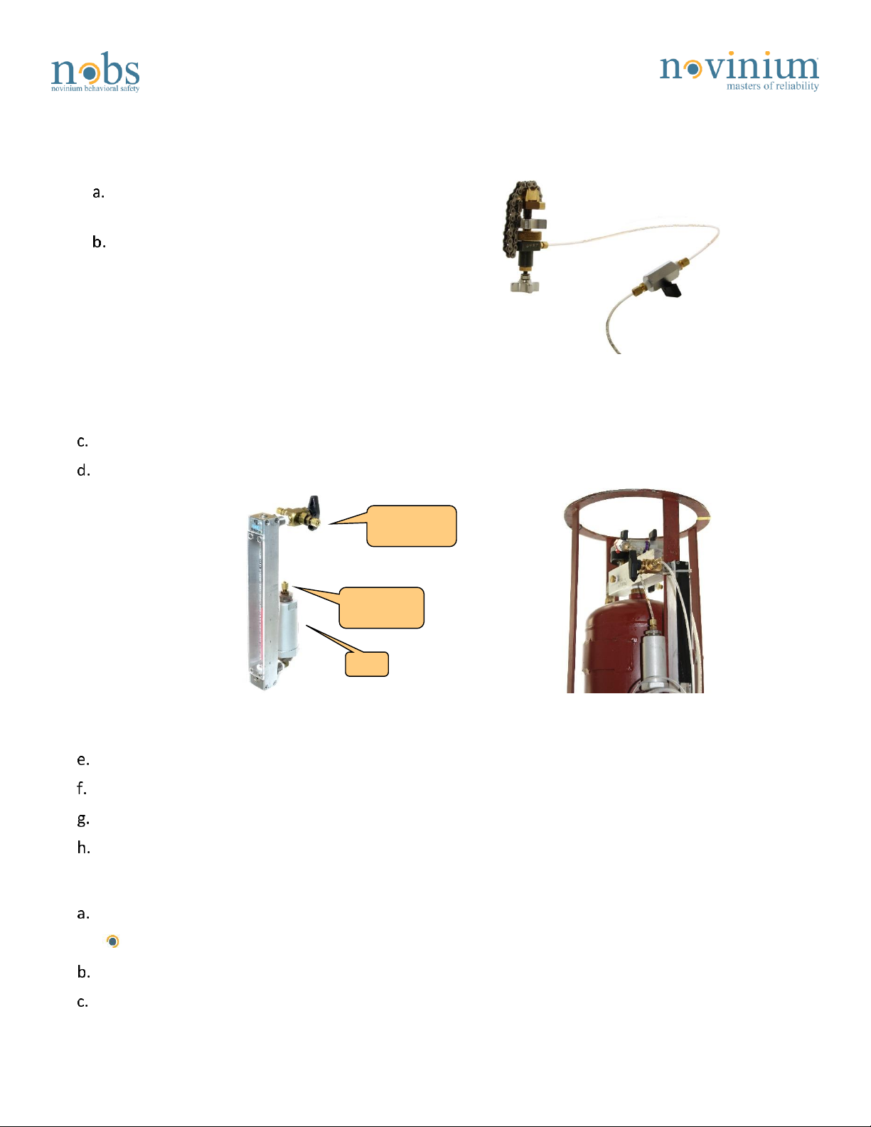
1. Injection tool (IT)......................................................................................................................................................... 2
2. Pressurized feed tanks. ............................................................................................................................................... 2
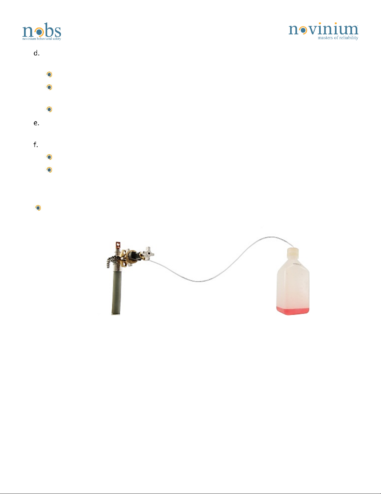
3. Receiver tanks............................................................................................................................................................. 3
Pre-Injection Check ................................................................................................................................................................. 4
1. Check for leaks. ........................................................................................................................................................... 4
Recording Tank Levels............................................................................................................................................................. 5
1. Record the injection start time and feed tank level. .................................................................................................. 5
Starting the Injection .............................................................................................................................................................. 5
1. Flow check................................................................................................................................................................... 5
2. Flush water and other fluids. ...................................................................................................................................... 5
3. Read the liquid flow meter. ........................................................................................................................................ 6
Estimating Fluids ..................................................................................................................................................................... 7
1. Estimate the current supplied fluid. ........................................................................................................................... 7
2. Estimate time for fluid arrival. .................................................................................................................................... 8
Fluid Arrival ............................................................................................................................................................................. 8
1. Flush the cable. ........................................................................................................................................................... 8
2. Reduce pressure to the tailored injection pressure (TIP). .......................................................................................... 8
3. Pin the outlet. ............................................................................................................................................................. 8
URD Cables and Pressurization ............................................................................................................................................... 9
1. Flow rate signals the end of injection. ........................................................................................................................ 9
2. Pin the inlet. .............................................................................................................................................................. 10
Recording Tank Levels........................................................................................................................................................... 11
1. Record the injection end time and feed tank level................................................................................................... 11
2. Remove the injection equipment. ............................................................................................................................ 11
3. Attach Craft Tags....................................................................................................................................................... 11
Resuming Component Installation........................................................................................................................................ 11

©Novinium, Inc. 2016, all rights reserved. NRI 603 –Small Diameter Cables –SPR
Revised: February 19, 2016 Page 2of 11
Installing Equipment
1. Injection tool (IT).
Connect 12 to 18 inches of 1/8” tubing
to the Injection Tool (IT).
Connect a 1/8” x 1/8” ball valve for
typical injections.
Ultrinium 733 fluid can thicken severely
at temperatures below 50°F (10°C).
Using a 1/8” x ¼” ball valve may
improve injection times with long tube
lengths.
Figure 1: Connect a ball valve
to the injection tool.
Install the liquid flow meter (rotometer).
Secure the liquid flow meter to the tank that is being used.
Figure 2: Liquid flow meter.
Figure 3: Flow meter secured on tank.
Connect the tank’s injection port (colored red) to the inlet of the flow meter.
Connect the tubing from the ball valve to the outlet of the flow meter.
Attach the injection tool to the IA, as in NRI 452.
Close all valves on the feed tank, flow meter, tubing, and gas tanks.
2. Pressurized feed tanks.
Attach an inline pressure gauge to the CO2 regulator of the used gas tank.
Select an inline gauge with a pressure range appropriate for the injection.
Connect the inline gauge to the feed tank.
Wheel the CO2 regulator out to prevent accidental over-pressurization.
Flow meter
outlet
Flow
meter inlet
Filter

©Novinium, Inc. 2016, all rights reserved. NRI 603 –Small Diameter Cables –SPR
Revised: February 19, 2016 Page 3of 11
Slowly pressurize the feed tank to the lesser of the adjusted flow pressure (AFP) or the maximum
working pressure rated for the tank.
If the AFP isn’t known, use NRI 352 to calculate the AFP.
The AFP can be increased by 10% for attended operations. However, if the injection needs to be
left unattended for any reason, reduce the pressure to the normal level.
This helps reduce the effects of any leaks that would have been found if attended.
Read the pressure on both the inline gauge and tank gauge. The two readings should be close to each
other.
Check the tank for any leaks.
If any leaks are found, relieve all pressure immediately and fix the leak.
A pressure relief valve prevents hardware operation above the design pressure. Do not tamper
with the pressure relief valve.
3. Receiver tanks.
On the receiver end of the cable sub-segment, install an injection tool connected to an empty
graduated flush bottle with 1/8” tubing. There are many sizes of flush bottles available.
Figure 4: Connect a flush bottle to the receiving injection tool.

©Novinium, Inc. 2016, all rights reserved. NRI 603 –Small Diameter Cables –SPR
Revised: February 19, 2016 Page 4of 11
A 140mL aluminum tank with a ball valve may substitute for the flush bottle in normal and unattended
injections. The ball valve allows injection to continue while the valve is closed.
Figure 5: 140mL tank with ball valve.
When possible, attach the
graduated flush bottle for easy
measurement of flushed fluid.
If left unattended under any
circumstances, place the flush bottle
or tank in a basin to prevent
accidental spills.
Figure 6: Use a spill basin to guard
against spills and overflow.
Pre-Injection Check
1. Check for leaks.
Before sending fluid straight to the cable, make sure each part of the injection assembly is leak-free. If
any leaks are found in the following process, close all valves, relieve pressure, and fix the leak.
Double-check that all valves on the feed tank, flow meter, tubing, and gas tank are closed.
Open the valve on the feed tank’s injection port. This will send fluid to the liquid flow meter. Wait for
three to four seconds and watch for leaks.
Open the valve on the liquid flow meter. This will send fluid to the inline ball valve. Wait for three to
four seconds and watch for leaks.
If no leaks are seen in the assembly, open the ball valve to send fluid to the injection tool. Watch for
leaks coming from the injection tool or the interface between the tool and the IA.

©Novinium, Inc. 2016, all rights reserved. NRI 603 –Small Diameter Cables –SPR
Revised: February 19, 2016 Page 5of 11
Recording Tank Levels
1. Record the injection start time and feed tank level.
Record the feed tank’s starting fluid
level in millimeters (mm) from the
bottom of the meniscus in the sight
gauge.
Record the injection start time.
Enter this information into
Knomentous.
Figure 7: Read the level from the
bottom of the fluid meniscus.
Starting the Injection
1. Flow check.
Verify flow into the cable by looking at the BBs in the liquid flow meter.
The BBs should rise to the top of the glass tube when flow starts and then slowly drop as flow
stabilizes.
If the BBs are dropping rapidly, there is a restriction in the cable.
Verify flow through the cable by checking the tubing on the receiver end of the cable.
Build up pressure in the line or submerge it into fluid.
Relieving the built up pressure should be audible, and air flow should cause bubbles in the fluid.
Bubbles may appear slowly due to restrictions in the cable.
2. Flush water and other fluids.
If water or other fluids are in the cable,
you may need to empty the receiver
bottle or tank multiple times during
injection.
To measure the flushed fluid, transfer all
fluid to a graduated flush bottle, if not
already in one.
Let the bottle sit for a few minutes. Water
and other fluids should separate if left
still.
Read the water and fluid levels on the
side of the bottle.
Figure 8: Transfer all fluids collected in the 140mL tank
to a graduated flush bottle.

©Novinium, Inc. 2016, all rights reserved. NRI 603 –Small Diameter Cables –SPR
Revised: February 19, 2016 Page 6of 11
Record all fluid and water flush and enter
the total volume into Knomentous.
3. Read the liquid flow meter.
The liquid flow meter shows the volume of fluid flowing through the glass tube every minute. It does
this by moving the two small BBs (one black, one silver) in the liquid flow meter’s glass tube.
The black BB is tinted black glass, while the silver BB is stainless steel. The black BB is more sensitive to
flow than the silver ball and must be located above the silver BB.
If the BBs are reversed, clearly label and contact supply chain to exchange for a new liquid flow meter.
The backing behind the glass tube has two scales printed on it. The left side, marked with “Silver ball”,
is the scale to read the silver BB’s position. The right side, marked with “Black ball”, is the scale to read
the black BB’s position. The unit of measurement of both scales is in mL/min, which is the same as
cc/min.
Figure 9: Black and silver ball scales.
Figure 10: Units of both scales.
When the black BB is above 11 cc/min on its scale, begin using the silver BB and its scale for readings
until the black BB drops back below 11 cc/min.
Monitoring the flow through the liquid flow meter can reveal much about the cable.

©Novinium, Inc. 2016, all rights reserved. NRI 603 –Small Diameter Cables –SPR
Revised: February 19, 2016 Page 7of 11
oA gradual decline in flow rate
means a clean cable.
oA sharp drop off in flow rate means
a restriction or blockage.
oA sharp drop near the start of
injection is a restriction/blockage
near the feed end of the cable.
oIf the restriction/blockage is
farther along the cable, it will take
longer to reach a sharp flow rate
drop.
Figure 11: Depiction of flow rates.
Estimating Fluids
1. Estimate the current supplied fluid.
Note the current fluid level in
millimeters (mm).
Subtract the current level
from the starting level.
Figure 12: Find the starting and current fluid levels.
To find the total fluid volume
in cubic centimeters (cc),
multiply the difference by the
tank factor for the feed tank
being used. Tank Factors can
also be found on a sticker on
the tank or in NRI 412.
2 or 3 Liter Tank Factor:
8.33 cc/mm.
9 Liter Tank Factor: 33.3
cc/mm.
Figure 13: Tank factor sticker.
0
10
20
30
40
50
60
70
80
90
100
010 20 30 40 50 60 70 80 90 100
Time
Feed Flow (% of scale)
unhindered flow
mid-span restriction
mid-span blockage
blocked near feed

©Novinium, Inc. 2016, all rights reserved. NRI 603 –Small Diameter Cables –SPR
Revised: February 19, 2016 Page 8of 11
2. Estimate time for fluid arrival.
Calculate how much time has passed since the injection began.
Use NRI 302, “The Cable Table”to calculate the target fluid amount the cable will take in millimeters
of tank height.
Divide the calculated target by the millimeters of fluid currently injected into the cable.
Multiply this number by the amount of time the injection has currently taken. This is the estimated
amount of time left for injection.
Fluid Arrival
1. Flush the cable.
Flush any contaminants out of the
cable.
Continue to flush until at least
25cc of clear, clean fluid comes
out of the cable.
Figure 14: Flush the cable.
2. Reduce pressure to the tailored injection pressure (TIP).
Reduce the adjusted feed pressure (AFP) to the insulation type’s tailored injection pressure (TIP).
The XLPE insulation TIP can be found in NRI 302, “The Cable Table.”
If the EPR insulation TIP is needed, calculate by dividing the XLPE TIP by 4.
3. Pin the outlet.
Close the ball valve to the injection tool to prevent fluid spray.
Use the injection tool to insert the plug pin into the IA; then remove the injection tool from the IA.
Check the plug pin hole for leaks and tap the pin in if it is not flush.
Wrap the saddle chain around a rag to protect and keep debris out of the injection tool.

©Novinium, Inc. 2016, all rights reserved. NRI 603 –Small Diameter Cables –SPR
Revised: February 19, 2016 Page 9of 11
URD Cables and Pressurization
Cables with small interstitial areas (space
between the strands) compared to the
insulation size need to be pressurized.
Typically, cables 250MCM and smaller need to
be pressurized. Extra fluid needs to be forced
into the strands with pressure.
If you have questions, contact engineering.
If the cable to be injected is of at least
350MCM size (Feeder) or is rated for a much
higher voltage level, follow the pressurization
procedure as stated in NRI 613 Large
Diameter Cables (Feeder) - SPR.
Figure 15: Thin insulation compared to the
conductor.
1. Flow rate signals the end of injection.
After pinning the outlet end, the flow into the cable will naturally begin declining as the fluid fills the
voids in the conductor.
Longer runs will take longer to drop.
The flow rate should eventually drop to 1cc/min or less.
If flow doesn’t drop to this level, there may be a leak somewhere in the system.
Search and repair fluid leaks at both cable ends.
If no leaks are found, there is either a fault or an undetected splice in the cable.
Locate and repair the splice or fault.
Re-inject the cable sub-segments.

©Novinium, Inc. 2016, all rights reserved. NRI 603 –Small Diameter Cables –SPR
Revised: February 19, 2016 Page 10 of 11
When the black BB reaches the
1cc/min mark on the black ball
scale, compare the fluid currently
supplied to the fluid floor and target
amounts.
If the supplied amount is above
the floor, the feed end may be
pinned.
1/0 and smaller cables may be
pinned even if the supplied fluid
is lower than the floor.
The limited space in these cables
might not allow enough fluid to
reach the floor. Pin the cable.
Figure 16: Liquid flow meter BBs are at 1cc/min.
2. Pin the inlet.
Close the ball valve to the injection tool to prevent fluid spray.
Insert the plug pin into the IA with the injection tool.
Remove the injection tool from the IA.
Check the plug pin hole for leaks and tap the pin in if it is not flush.
Figure 17: Non-flush plug pin.
Wrap the saddle chain around a rag to protect and keep debris out of the injection tool.

©Novinium, Inc. 2016, all rights reserved. NRI 603 –Small Diameter Cables –SPR
Revised: February 19, 2016 Page 11 of 11
Recording Tank Levels
1. Record the injection end time and feed tank level.
Record the feed tank’s ending fluid level in millimeters (mm) from the sight gauge.
Record the time the injection ended.
Enter this information into Knomentous.
2. Remove the injection equipment.
Close all valves on the injection assembly and turn off the CO2 supply.
Vent all pressure from the tanks if they will be moved or stored for the night.
Open the valve on the feed tank’s injection port to vent pressure and fluid from the liquid flow meter
back into the feed tank.
3. Attach Craft Tags
The Novinium certified craftsman must attach their craft tag onto each IA or component body. Secure the
tag with tape to ensure it will not move.
Figure 18: Craft tag placed over the IA.
Figure 19: Craft tag placed on the component.
The SPR injection process is complete.
Resuming Component Installation
SPR injection interrupts the component installation. Resume installation using the associated NRI.
Attach warranty tags.
Enter data into Knomentous.
Table of contents
Other Novinium Cables And Connectors manuals