Novus TELIK TRAFO LITE User manual

TELIK TRAFO LITE
USER GUIDE V1.0x A

NOVUS AUTOMATION 2/31
1SAFETY ALERTS ...........................................................................................................................................................................3
2PRESENTATION.............................................................................................................................................................................4
3IDENTIFICATION ............................................................................................................................................................................5
3.1 OVERVIEW..............................................................................................................................................................................5
3.2 IDENTIFICATION ....................................................................................................................................................................6
4INSTALLATION ..............................................................................................................................................................................7
4.1 INSTALLATION .......................................................................................................................................................................7
4.1.1 INSTALLATION RECOMMENDATIONS .........................................................................................................................7
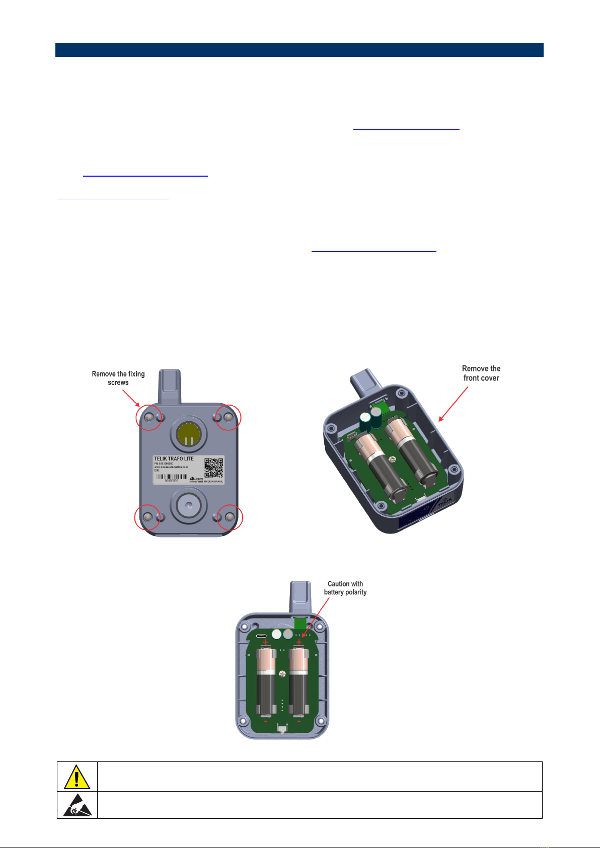
4.1.2 POWER SUPPLY ............................................................................................................................................................7
4.1.2.1 BATTERY LIFESPAN ..............................................................................................................................................8
4.1.3 POWER KEY AND OPERATION LED ............................................................................................................................9
4.2 MECHANICAL INSTALLATION...............................................................................................................................................9
4.2.1 DIMENSIONS ..................................................................................................................................................................9
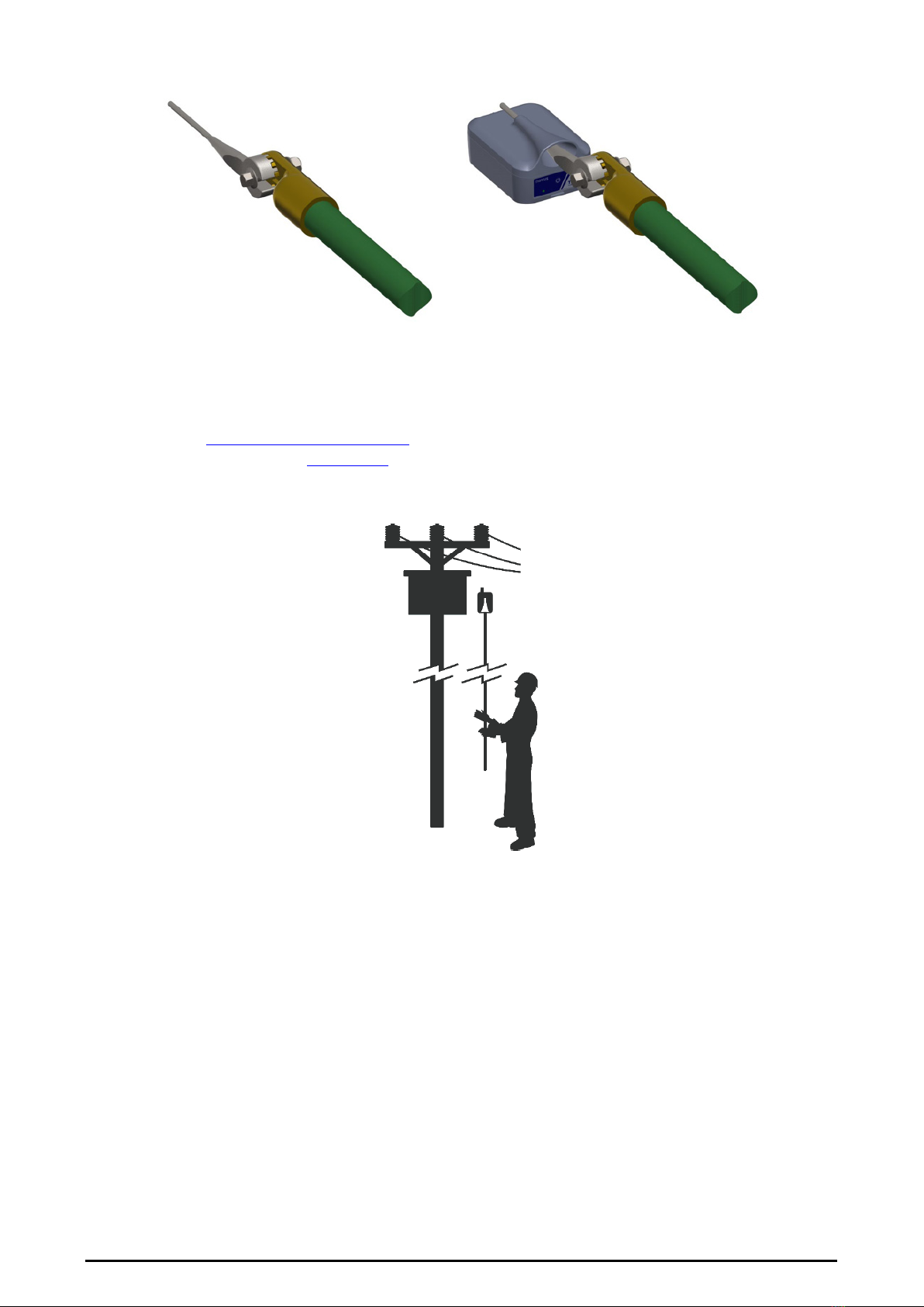
4.2.2 INSTALLATION HEAD ....................................................................................................................................................9
4.2.3 TRANSFORMER INSTALLATION.................................................................................................................................10
5COMMUNICATION INTERFACES ...............................................................................................................................................11
5.1 USB INTERFACE ..................................................................................................................................................................11
5.2 LORAWAN INTERFACE .......................................................................................................................................................11
5.2.1 HOW TO FORMAT TELIK TRAFO LITE MESSAGES ..................................................................................................11
5.2.1.1 UPLINK ..................................................................................................................................................................11
6OPERATION .................................................................................................................................................................................14
6.1 TELIK TRAFO LITE CONFIGURABLE PARAMETERS........................................................................................................15
6.1.1 FACTORY DEFAULT ....................................................................................................................................................15
7CONFIGURATION SOFTWARE...................................................................................................................................................17
7.1 NXPERIENCE........................................................................................................................................................................17
7.2 NXPERIENCE MOBILE .........................................................................................................................................................17
7.3 SETTING THE DEVICE.........................................................................................................................................................17
7.3.1 SETTINGS .....................................................................................................................................................................17
7.3.1.1 GENERAL SETTINGS...........................................................................................................................................17
7.3.1.2 ALARMS ................................................................................................................................................................18
7.3.1.3 COMMUNICATION................................................................................................................................................18
7.3.1.4 PROVISIONING.....................................................................................................................................................18
7.3.1.5 LORAWAN COMMUNICATION.............................................................................................................................19
7.3.2 DIAGNOSTICS ..............................................................................................................................................................20
7.3.2.1 INFORMATION ......................................................................................................................................................20
7.3.2.2 INPUTS..................................................................................................................................................................21
7.4 REGISTERING YOUR DEVICE IN NOVUS CLOUD ............................................................................................................22
7.4.1 REGISTRATION VIA NXPERIENCE MOBILE ..............................................................................................................22
7.4.2 REGISTRATION VIA NOVUS CLOUD..........................................................................................................................25
7.4.3 MANAGING YOUR DEVICE IN NOVUS CLOUD..........................................................................................................26
8TROUBLESHOOTING ..................................................................................................................................................................27
9LORA CONNECTIVITY PLAN ......................................................................................................................................................28
9.1 DATA USAGE........................................................................................................................................................................28
10 TECHNICAL SPECIFICATION .................................................................................................................................................29
10.1 WIRELESS CONECTIVITY ...............................................................................................................................................29
10.2 CERTIFICATIONS.............................................................................................................................................................30
11 WARRANTY..............................................................................................................................................................................31

NOVUS AUTOMATION 3/31
1SAFETY ALERTS
The symbols below are used in the device and throughout this manual to draw the user’s attention to valuable information related to device safety
and use.
CAUTION
Read the manual fully before installing and
operating the device.
CAUTION OR HAZARD
Risk of electric shock.
ATTENTION
Material sensitive to static charge. Check
precautions before handling.
All safety recommendations appearing in this manual must be followed to ensure personal safety and prevent damage to the instrument or system.
If the instrument is used in a manner other than that specified in this manual, the device’s safety protections may not be effective.

2PRESENTATION
Telik Trafo Lite is an IoT device for temperature monitoring in transformers. It is easy to install, with magnetic fastening, attached to the transformer
in a non-invasive way. Besides being compact and robust, it was developed with extremely low power consumption techniques and is powered by
two non-rechargeable batteries that have a useful lifespan of 5 to 10 years (depending on the configuration applied and the signal quality).
With easy network commissioning, Telik Trafo Lite has LoRaWAN communication to send data such as battery temperatures and voltage to online
dashboards. This data helps to monitor the behavior of transformers in a faster and more efficient way, identify overloads and, since the highest
failure rate in transformers is caused by overloading, reduce losses, and prevent unnecessary expenses.
Telik Trafo Lite is a class A End Device within the LoRaWAN architecture.
Figure 1 –Example of a LoRaWAN network structure

NOVUS AUTOMATION 5/31
3IDENTIFICATION
3.1 OVERVIEW
The device housing is made of Polycarbonate, a material with V0 flame retardant and UVA/UVB protection, and has been designed to meet IP66
protection. This allows Telik Trafo Lite to be exposed to the weather.
The sealing system has a silicone seal between the cover and the base of the housing.
The front cover has a hole for the installation head (purchased separately), used on the operating pole (see INSTALLATION HEAD section).
Figure 2 –Overview
The bottom of the housing has a Power key and an operation LED (see POWER KEY AND OPERATION LED section), which allow you to turn the
device on or off and obtain information about its status and connection:
Figure 3 –Bottom
On the back, built into the housing, are two neodymium magnets, which ensure the magnetic attachment of the device to the metal housing of the
transformer. Next to one of these magnets is the temperature sensor, which, in contact with the transformer, transmits the temperature signal to the
device:
Figure 4 –Back

NOVUS AUTOMATION 6/31
3.2 IDENTIFICATION
The identification label, located on the back of the Telik Trafo Lite housing, contains its model, serial number and DevEUI. This data, along with
"JoinEUI" and "AppKey", is required to register the device on the Network Server. For security reasons, only the DevEUI is shown on the label.
This information come preloaded from the factory with the default used by the NOVUS connectivity plan (see NOVUS CONNECTIVITY PLAN section).
If needed to use the device with another Network Server, you can change "JoinEUI" and "AppKey" parameters.
To register the device in NOVUS Cloud with the NOVUS connectivity plan, you can use NXperience Mobile (see NXPERIENCE MOBILE section)
to get all the QR Code information. No need to open the housing.
Figure 5 –Identification label

4INSTALLATION
4.1 INSTALLATION
4.1.1 INSTALLATION RECOMMENDATIONS
If there is coverage for the LoRaWAN network in the location where the device will be installed, the device must be configured, i.e., it must be
registered in the application Network Server before performing the physical installation at the transformer. If the application used is NOVUS Cloud,
a NOVUS platform, you can register it through NXperience and NXperience Mobile (see CONFIGURATION SOFTWARE chapter).
When using another Network Server, you must follow the recommendations of the selected server. In this case, when using the USB interface of the
device, you can use NXperience to change the JoinEUI and AppKey values.
Once Telik Trafo Lite has been registered, simply turn it on using the Power key and wait for the status LED to indicate the three blinks code 3 (see
table in POWER KEY AND OPERATION LED section).
Once you are certain that the device has successfully connected to the LoRaWAN network, you can install the device at the transformer (see
TRANSFORMER INSTALLATION section).
If the device failed to successfully connect to the LoRaWAN network, follow the steps below:
1) Check that it has been correctly registered on the Network Server.
2) Check that there is good LoRaWAN coverage of the Network Server chosen for the region where the device is being installed.
3) If the Telik Trafo Lite fails to connect after 5 minutes, turn it off (see POWER KEY AND OPERATION LED section).
4) Find a higher position that allows you to better position the antenna.
5) Turn the device back on, with the antenna positioned upwards.
6) Wait up to 5 minutes to check if it was able to connect to the network.
4.1.2 POWER SUPPLY
The device is powered by two Lithium Thionyl Chloride (Li-SOCl2) batteries of size 14500 and 3.6 V. If you need to replace them, we recommend
using the batteries distributed by NOVUS.
To replace the batteries, you must remove the four screws from the back and then the front cover of the housing:
Figure 6 –Opening the housing
When replacing batteries, carefully observe their polarity:
Figure 7 –Replacing batteries
When closing the housing, please check the position of the silicone seal. Correct assembly ensures the original protection
rating.
Static sensitive material. Be sure to take necessary precautions before handling it.

NOVUS AUTOMATION 8/31
To complete the battery replacement process, you must use the Power key to inform the device that new batteries have been installed. To do this,
follow the steps below:
1) Ensure that the device is turned off. If it is on, you must turn it off.
To find out if the device is on, you can give a quick click on the Power key. If the LED lights up while the key is pressed, this means that the
device is on.
2) Press the Power key and keep it pressed until step 5.
3) Wait until the LED blinks quickly (approximately 2 seconds).
4) Wait until the LED blinks slowly (approximately 5 seconds).
5) Release the Power key.
6) This will restore the battery charge indicators.
7) After the procedure has been performed, the device will start up and renew the connection to the Network Server.
For information on estimated battery lifespan with respect to configuration, see BATTERY LIFESPAN section.
4.1.2.1 BATTERY LIFESPAN
Optimized lifespan is an important feature of battery powered LoRaWAN devices.
The Telik Trafo Lite batteries have a low discharge rate, aiming for 8 to 10 years of autonomy. Depending on the configuration of the device, this
period can be even longer.
The main factors influencing the battery lifespan are: Ambient temperature, transmission and sensor reading intervals, transmission power (TX Power)
and Spreading Factor (SF).
Based on different configurations, the table below gives an estimation of battery lifespan. As a reference, these values use an ambient temperature
between 20 and 25 °C (68 and 77 °F).
DAILY
TRANSMISSIONS
DAILY READINGS
(SENSORS) TX POWER SF LIFESPAN
12 72 20 dBm 7 More than 10 years
12 72 20 dBm 12 More than 10 years
24 144 20 dBm 7 More than 10 years
24
144
20 dBm
12
Around 4.5 years
48
288
20 dBm
7
More than 10 years
48 288 20 dBm 12 Around 2.5 years
144 864 20 dBm 7 More than 10 years
144 864 20 dBm 12 Around 1.5 year
Table 1 –Battery lifespan
The data above are estimates and serve as a basis for an approximate range. By using a lower TX power, it is possible to extend these values.
The Spreading Factor (SF) impacts critical parameters: Range, transmission rate and transmission time. Changing the SF value will impact these
three variables, directly influencing the energy consumption. SF values range from 7 to 12. The closer you get to SF7, the lower the power
consumption; therefore, the closer to SF12, the higher the power consumption.
The environment temperature is another key factor that determines the lifespan and durability of batteries. Exceedingly elevated temperatures
increase the chemical reactions inside the battery and consequently the self-discharge. Extremely low temperatures reduce the battery ability to
produce energy.
BATTERY PASSIVATION
Passivation is a common occurrence in Li-SOCl2 batteries (used by Telik Trafo Lite). Storing the batteries for an extended period or extremely low
power consumption can form an insulating film inside the battery, which would restrict the current flow and cause a drop in the nominal voltage of the
battery. Despite this, passivation has a beneficial effect on Li-SOCl2 batteries as it reduces self-discharge. This allows them to be stored for extended
periods.
Passivation can be characterized by a drop in battery voltage during periods of consumption.
HOW TO IDENTIFY PROBLEMS WITH THE BATTERIES?
Telik Trafo Lite performs periodic readings of battery voltage and records the minimum, maximum, average, and instantaneous values. This data is
sent daily to NOVUS Cloud, where it can be accessed and analyzed.
When the voltage levels exceed the previously configured limits, an alarm message is sent, alerting about the battery status. This allows you to
identify problems such as battery discharge or passivation.

NOVUS AUTOMATION 9/31
4.1.3 POWER KEY AND OPERATION LED
To turn on the device, simply press the Power key, located on the bottom of the housing, until the status LED starts operating. Through the following
blink codes, the LED informs the device status:
FLASHING TYPES
STATUS
Burst of fast flashing The system has been booted.
2 blinks The device is trying to connect.
3 blinks The connection was established.
Table 2 –Status LED
After being turned on for the first time, Telik Trafo Lite starts the connection process, where it automatically changes its parameters to achieve a
greater range and ensure low power consumption.
In the first stage of this process, the interval between connection attempts is 1 minute, while maximum transmission power and the best data
transmission rate are achieved. If the connection is not established in the first stage, the next attempts will occur successively in 10, 30, and 60
minutes.
In the last stage, the device keeps the power level and the Baud Rate static and sets the connection interval to 12 hours.
While trying to establish the connection, the status LED will only operate for the first 5 minutes.
After connection, the status LED will operate for only 1 minute. After this period, it will remain off.
To verify whether Telik Trafo Lite is on or off, give a quick click on the Power key. If the LED lights up while the key is pressed,
the device is on. Otherwise, the device is off.
To check the status of the device, you can give a short click on the Power key. This will activate the LED for a while longer. If the LED doesn't light
up, it means that the device is turned off.
To turn off the Telik Trafo Lite, you must press the Power key until the LED blinks quickly and continuously (for approximately 5 seconds). After that,
release the key. The device will go into stand-by mode, i.e., it will be inoperative until it is turned on again.
4.2 MECHANICAL INSTALLATION
4.2.1 DIMENSIONS
Telik Trafo Lite has the following dimensions:
Figure 8 –Dimensions
4.2.2 INSTALLATION HEAD
Telik Trafo Lite has an optional accessory, which allows you to attach it to the operating pole:
Figure 9 –Installation head

NOVUS AUTOMATION 10/31
Once the installation head is attached to the operating pole and attached to the front of the Telik Trafo Lite, you can install it in the transformer:
Figure 10 –Accessory installation
4.2.3 TRANSFORMER INSTALLATION
Before connecting the Telik Trafo Lite to the operating pole and installing the device in the transformer, you must ensure that it is registered on the
application server (see INSTALLATION RECOMMENDATIONS section). This registration is your own responsibility.
After following the steps explained in the INSTALLATION section, simply bring the device to the installation point. Since it uses magnets, it is
recommended that you keep it away from other metal parts during lifting to the installation point.
The installation of the device in a transformer must be carried out by a trained professional, respecting the safety protocols for handling the operating
pole.
Figure 11 –Transformer installation

NOVUS AUTOMATION 11/31
5COMMUNICATION INTERFACES
5.1 USB INTERFACE
Telik Trafo Lite has a USB interface, located inside the housing:
Figure 12 –USB Interface
To access it, you must remove the four screws from the back of the housing and remove the front cover.
You can use the USB interface to update firmware, configure and perform diagnostics on the device using the NXperience software (see
CONFIGURATION SOFTWAREchapter). To connect your Telik Trafo Lite to a computer, use a micro-USB cable (not supplied).
When closing the housing, please check the position of the silicone seal. Correct assembly ensures the original protection
rating.
Static sensitive material. Be sure to take necessary precautions before handling it.
5.2 LORAWAN INTERFACE
LoRaWAN is the protocol that defines the parameters and architecture of the data communication system over LoRa technology. It is compatible with
the following operating bands: LA915 (Brazil) and AU915 (other countries) The protocol also defines security features, data traffic rules, quality of
service, and power settings to maximize the correlation between signal quality and battery lifespan. It is a type of technology that allows low data
traffic.
A LoRaWAN system contains four main elements:
1) Devices: Also called "End Devices", these are the devices that produce data, that is, that perform data acquisition and/or operate on the
environment by remote command. Telik Trafo Lite is an End Device.
2) Gateways: These are the devices that receive messages from End Devices and send these messages to Network Servers. A single Gateway
can receive messages from several End Devices. In addition, multiple Gateways can receive messages from the same End Device, which
allows better coverage and reliability for the network.
3) Network Server: This is the server that receives and manages the messages received by the Gateways. A single Network Server can
receive messages from several Gateways.
4) Application Server: This is the server that communicates with the Network Server and processes the data produced by the End Devices,
in other words, where the data produced by the End Devices are forwarded to and where the messages that should be sent to the End
Devices come from.
5.2.1 HOW TO FORMAT TELIK TRAFO LITE MESSAGES
5.2.1.1 UPLINK
Telik Trafo Lite sends several types of messages on different ports of the LoRaWAN network.
•Recurrent temperature messages from the transformer will be sent through port 1. The values are multiplied by 10:
Description
INSTANT
AVERAGE
MINIMUM
MAXIMUM
Order
LSB
MSB
LSB
MSB
LSB
MSB
LSB
MSB
Byte
0
1
2
3
4
5
6
7
Table 3 –Recurrent messages
Instant: Value obtained from the sensor reading.
Average: Average value of the sensor readings within the last publication interval.
Minimum: Minimum value read within the last publication interval.
Maximum: Maximum value read within the last publication interval.
LSB: Least significant byte of the 16-bit value.
MSB: Most significant byte of the 16-bit value

NOVUS AUTOMATION 12/31
EXAMPLE:
Message = 310141012A014B01
INSTANT
AVERAGE
MINIMUM
MAXIMUM
31 01 41 01 2A 01 4B 01
Table 4 –Example 1
INSTANT = 0x0131 = 305 = 30.5 °C
AVERAGE = 0x0141 = 321 = 32.1 °C
MINIMUM = 0x012A = 298 = 29.8 °C
MAXIMUM = 0x014B = 331 = 33.1 °C
•Delayed temperature messages from Telik Trafo Lite will be sent through port 4. The values are multiplied by 10:
DELAY IN MINUTES FREQUENCY IN
MINUTES PERIODIC MESSAGES DELAYED
LSB
MSB
LSB
MSB
LSB - MSB
0 1 2 3 4 + N
Table 5 –Delayed messages
Delay in minutes:Time elapsed since the first periodic transmission failure.
Frequency in minutes:Configured publication interval.
Periodic messages delayed:Data from delayed periodic messages.
EXAMPLE:
Message = 0C000500310141012A014B01410151012B014C01510161012C014D01
DELAY IN MINUTES
FREQUENCY IN
MINUTES PERIODIC MESSAGES DELAYED
0C
00
05
00
310141012A014B01410151012B014C01510161012C014D01
Table 6 –Example 2
DELAY IN MINUTES = 0x000C = 12 minutes
FREQUENCY IN MINUTES = 0x0005 = 5 minutes
PERIODIC MESSAGES DELAYED = 310141012A014B01 410151012B014C01 510161012C014D01
310141012A014B01 – Oldest message delayed by 12 minutes.
410151012B014C01 – Oldest message delayed by 7 minutes.
510161012C014D01 – Oldest message delayed by 2 minutes.
•Daily internal temperature messages will be sent through port 5. The values are multiplied by 10:
INSTANT AVERAGE MINIMUM MAXIMUM
LSB
MSB
LSB
MSB
LSB
MSB
LSB
MSB
0
1
2
3
4
5
6
7
Table 7 –Daily internal temperature messages
•Daily battery voltage messages will be sent through port 6. The values are multiplied by 10:
INSTANT AVERAGE MINIMUM MAXIMUM
0 1 2 3
Table 8 –Daily battery voltage messages

NOVUS AUTOMATION 13/31
•Alarm messages will be sent through port 2:
DELAY IN MINUTES
ALARM TYPE
MAIN VALUE
AUXILIARY VALUE
LSB MSB BYTE LSB MSB LSB MSB
0 1 2 3 4 5 6
Table 9 –Alarm messages
Delay in minutes:Time (in minutes) elapsed from the occurrence of the alarm to the moment the message is sent.
Alarm type:Alarm code.
Main value:Temperature reading at the time of alarm.
Auxiliary value:Additional reading.
The table below presents alarm codes:
CODE DESCRIPTION MAIN VALUE (x10) AUXILIARY VALUE (x10)
0xF0 In a maximum temperature alarm condition. Transformer temperature –
0xF1 Out of a maximum temperature alarm condition. Transformer temperature
Maximum temperature reached
during alarm
0xF4 In a temperature variation alarm condition. Transformer temperature Current temperature condition
0xF5 Out of a temperature variation alarm condition. Transformer temperature
Maximum temperature reached
during alarm
0xF2 In a low-battery alarm condition. Battery voltage –
0xF3 Out of a low-battery alarm condition. Battery voltage –
Table 10 –Alarm codes
EXAMPLE:
Message = 0100F436025500
DELAY IN MINUTES
ALARM TYPE
MAIN VALUE
AUXILIARY VALUE
01
00
F4
36
02
55
00
Table 11 –Example 3
DELAY IN MINUTES = 0x0001 = 1 = Message sent 1 minute after alarm
ALARM TYPE = 0xF4 = In a temperature variation alarm condition
MAIN VALUE = 0x0236 = 566 = 56.6 °C
AUXILIARY VALUE = 0x0055 = 85 = 8.5 °C / minute

NOVUS AUTOMATION 14/31
6OPERATION
Telik Trafo Lite monitors the transformer temperature, performing acquisitions at configurable regular intervals and publishing the acquired data
(also at configurable regular intervals) through the LoRaWAN protocol. The published data is received by a Network Server, which, in turn, forwards
it to a cloud application, such as NOVUS Cloud.
There are two ways to publish data:
1) Confirmed mode: In confirmed mode, the device sends the message and waits for a confirmation from the Network Server before
considering the sending successful.
2) Non-confirmed mode: In non-confirmed mode, messages are sent and considered successful without any confirmation. There is no
guarantee of message delivery.
Although the LoRaWAN protocol recommends you use non-confirmed messages to reduce the number of messages transmitted in the network (since
each confirmation counts as one message), it has a message confirmation feature to minimize data loss. Still, there is no guarantee that 100 % of
the messages will be delivered. There may be times when no Gateway received the message from the device, either due to packet collision or poor
coverage at the time of publication.
To minimize data loss, Telik Trafo Lite has an internal memory that, when in confirmation mode, allows to store up to 10 messages for later
retransmission (in case the device does not receive confirmation of the messages sent). This feature can increase the number of messages
transmitted on the network and, consequently, produce a possible additional cost in the LoRaWAN plan, as well as increase battery consumption and
decrease autonomy. Nevertheless, it is an important feature to ensure message delivery, especially in a region with poor coverage.
The LoRaWAN protocol has an ADR (Adaptive Data Rate) mode, which, when enabled, regardless of whether the message sending configuration is
"confirmed" or "non-confirmed", allows the Network Server to request reconfigurations in power and transmission rate. This is used to try to ensure
effective communication between the device and the Gateway that receives the messages and sends them to the Network Server.
Besides ADR mode, Telik Trafo Lite has algorithms that automatically reconfigure the transmission parameters upon receiving no response to
confirmed messages and no response to a Join request.
Data Rates related to the SF (Spreading Factor) are defined in the LoRaWAN protocol. The higher the SF, the lower the Data Rate.
SF
DATA RATE
RATE IN BITS/S
7 5 5470
8 4 3125
9 3 1760
10
2
980
11
1
440
12 0 250
Table 12 –Spreading Factor
Transmission power levels are also defined in the LoRaWAN protocol. Both the transmission power and the Data Rate influence the battery lifespan.
This happens because in a place with poor coverage, Telik Trafo Lite needs to spend more energy (with a lower Data Rate and higher transmission
power) to successfully publish a packet.
LORAWAN INDEX
TRANSMISSION POWER
5
20 dbm
6
18 dbm
7 16 dbm
8 14 dbm
9 12 dbm
10 10 dbm
Table 13 –LoRaWAN index
Each Telik Trafo Lite has a unique and non-configurable identifier (DevEUI). In addition, each device has a JoinEUI and an AppKey. These two
parameters are configurable. You will need this set of identifiers to connect to any Network Server.
1)
Choosing confirmed mode impacts data consumption. In this mode, sending one message accounts for two messages
in the data packet, i.e., data consumption in confirmed mode is twice as high as in non-confirmed mode.
2) If your Telik Trafo Lite is configured to send non-confirmed messages and the Network Server is not receiving the
messages and/or the device is repositioned, it is recommended to turn the device off and on again so that it starts Join
with lower power and Data Rate and later reconfigures the most appropriate parameters (if ADR is enabled) with the
Network Server.
3) Telik Trafo Lite automatically renews the connection to the Network Server 24 hours after a connection is established. In
other words, the connection will be renewed at least once a day.

NOVUS AUTOMATION 15/31
6.1 TELIK TRAFO LITE CONFIGURABLE PARAMETERS
Through NXperience software, you can configure the following parameters:
•Publication interval:Allows you to set the time in minutes between regular publications. In this interval, the device will publish a temperature
analysis of the last interval. From 1 to 1440 minutes (24 hours).
•Acquisition interval: Allows you to set the time in seconds between acquisitions. This interval must be less than or equal to the publication
interval. These acquisitions will be used to generate the analytical data that will be published in the publication interval and for the device to
analyze alarm situations that may generate instant messages.From 10 to 43200 seconds (12 hours).
•Confirmation of recurrent messages:Allows you to define whether messages that are sent frequently should receive confirmation. When this
feature is enabled, the device will wait for a confirmation response from the Network Server after a message is sent.
If this confirmation is not received, the device will try to send the message again, placing it in a circular queue for later publishing in case of
failure.
When this feature is disabled, messages are sent, and the sending is considered successful and there is no delivery confirmation.
•Confirmation of alarm messages:Identical to the previous parameter but applied only for alarm messages.
•Alarms: Allows the device to send messages informing you of the beginning and end of an alarm condition.
•Maximum temperature alarm: Allows alarm conditions to be checked at each acquisition interval. This is the minimum time required for an
alarm to change its status.
oSetpoint: Value to be exceeded to satisfy the alarm situation. From 0 to 125 °C (32 to 257 °F).
oHysteresis: Barrier to be overcome to leave the alarm situation.From 0 to 10 °C (32 to 50 °F).
•Maximum heating rate: Allows you to set the maximum allowed heating rate per time interval. The value is informed in °C/hour. From 0 to 100
°C/hour (32 to 212 °F/hour).
•Hysteresis for heating rate:Allows you to define how many °C/hour the heating rate must decrease for the device to leave the alarm condition.
From 0 to 50 °C/hour (32 to 122 °F/hour).
•Low battery alarm: Allows the device to send messages about the battery alarm. Battery voltage is checked only once a day.
•Minimum battery voltage: Allows you to define the voltage that the battery can reach in transmission mode. If the voltage is lower than the
configured value, the device will enter alarm condition. The value is informed in Volts (see BATTERY LIFESPAN section). From 2.0 to 7.0 Volts.
•Hysteresis:Allows you to define how many Volts above the minimum voltage the battery must reach in transmission mode to leave the alarm
condition. The value is informed in Volts. From 0 to 2.0 Volts.
•ADR mode:When enabled, it obeys commands received from the Network Server to reconfigure the transmission system (if it is within the limits
configured on the device).
•Initial transmission power: Power used at system startup. From 10 to 20 db.
•Minimum transmission power: Lower power limit of the operation.
•Maximum transmission power: Higher power limit of the operation.
•Initial SF: SF used at system startup. From 7 to 12.
•Minimum SF: Operation lower limit.
•Maximum SF: Operation higher limit.
•JoinEUI: Application identifier. You are only allowed to write to this field when the device is configured on an application server other than NOVUS
Cloud.
•AppKey: Application key. You are only allowed to write to this field when the device is configured on an application server other than NOVUS
Cloud.
•Registering account:Allows you to define which connection parameters will be used. When selecting the "NOVUS Cloud" option, the device
will assume default values for JoinEUI and AppKey. When selecting the "Custom" option, the device will assume the values configured in the
respective fields.
6.1.1 FACTORY DEFAULT
Telik Trafo Lite leaves factory previously configured to operate with NOVUS Cloud. See below the default settings:
PARAMETER DEFAULT SETTING
Acquisition interval 600 seconds (10 minutes)
Publication interval
60 minutes (1 hour)
Confirmation of recurrent messages
Disabled
Confirmation of alarm messages
Disabled
ADR mode Enabled
Initial transmission power 20 db
Minimum transmission power 10 db
Maximum transmission power
20 db
Initial SF
9
Minimum SF
7
Maximum SF 12

NOVUS AUTOMATION 16/31
PARAMETER
DEFAULT SETTING
Registering Account NOVUS Cloud
Maximum temperature alarm Setpoint: 80 °C (176 °F)
Hysteresis:
3 °C (37.4 °F)
Maximum heating rate alarm
Setpoint: 20 °C/hour (68 °F/hour)
Hysteresis:3 °C/hour (37.4 °F/hour)
Low battery alarm Setpoint: 6.0 Volts
Hysteresis: 0.5 Volts
Table 14 –Factory default
In the Finishing section of the NXperience software, you can use the Factory Settings button to restore the device to factory defaults.
Working power levels, data transmission rate, message confirmation mode, and intervals are all factors that directly
impact the battery consumption of the device.

NOVUS AUTOMATION 17/31
7CONFIGURATION SOFTWARE
7.1 NXPERIENCE
The NXperience software allows you to configure and analyze the data from Telik Trafo Lite. You can explore all the features and update the device
firmware via USB.
Besides the connection via USB, NXperience allows you to read and send settings to the device remotely through NOVUS Cloud.
This manual describes the generic features of the software. For more information, check the specific operations manual. The software can be downloaded
for free from the Download Area of our website www.novusautomation.com.
7.2 NXPERIENCE MOBILE
The NXperience Mobile app is a tool to simplify the process of registering your Telik Trafo Lite in NOVUS Cloud. It is available for Android and iOS
smartphones.
NXperience Mobile can be downloaded for free from Google Play Store and App Store.
7.3 SETTING THE DEVICE
7.3.1 SETTINGS
7.3.1.1 GENERAL SETTINGS
Figure 13 –General settings
INFORMATION
•Serial Number: Displays the serial number of the device.
•Model: Displays the device model.
•Firmware Version: Displays the firmware version of the device.
•DeviceEUI: Displays the End Device identification number.
GENERAL SETTINGS
•Acquisition interval: Allows you to set the transformer temperature reading interval.
•Publication interval: Allows you to set the publication interval of the transformer temperature data.
•Confirmation of periodic messages: Allows you to set the type of periodic messages sending (With or without confirmation).
•Confirmation of alarms messages: Allows you to set the type of alarm message sending (With or without confirmation).
All the parameters in this section must be in accordance with the contracted data plan.

NOVUS AUTOMATION 18/31
7.3.1.2 ALARMS
Figure 14 –Alarms
TRANSFORMER TEMPERATURE ALARMS
•Temperature alarm Setpoint: Allows you to set the temperature for the Setpoint alarm.
•Hysteresis: Allows you to set a hysteresis value for the Setpoint alarm.
•Maximum heating rate:Allows you to set a value for the maximum heating rate.
•Hysteresis for heating rate:Allows you to set a hysteresis value for the heating rate.
BATTERY VOLTAGE ALARM
•Minimum voltage: Allows you to set a minimum voltage for the Setpoint alarm.
•Hysteresis: Allows you to set a hysteresis value for the minimum allowed voltage.
7.3.1.3 COMMUNICATION
Figure 15 –Communication
7.3.1.4 PROVISIONING
•Communication server: Allows you to set the communication server to be used. When selecting the "NOVUS Cloud" option (Available only for
Brazil), it will not be necessary to configure LoRaWAN communication configuration parameters, as shown in the figure above.
When selecting the "Other Network Server" option, you will need to configure the JoinEUI and AppKey parameters in the LoRaWAN
Communication section.

NOVUS AUTOMATION 19/31
7.3.1.5 LORAWAN COMMUNICATION
Figure 16 –Setting up LoRaWAN communication parameters
Regardless of the communication server used, you must set the ADR Mode parameter:
•ADR Mode: If enabled, the device will adjust the SF (Spreading Factor) and TX Power according to the values received by the LNS (LoRaWAN
Network Server).
By clicking the Advanced settings button, you can configure the other parameters:
Figure 17 –Advanced settings
•Initial transmission power: Allows you to set the power to be used when starting the system.
•Power correction (Min.): Allows you to set a lower power limit for the operation.
•Power correction (Max): Allows you to set an upper power limit for the operation.
•Initial spreading factor: Allows you to set the Spreading Factor to be used when starting the system.
•Spreading factor (Min.): Allows you to set a minimum limit for the spreading correction.
•Spreading factor (Max): Allows you to set a maximum limit for the spreading correction.

NOVUS AUTOMATION 20/31
7.3.2 DIAGNOSTICS
7.3.2.1 INFORMATION
Figure 18 –Information
INFORMATION
•Serial Number: Displays the serial number of the device.
•Model: Displays the model of the device.
•Firmware Version: Displays the firmware number of the device.
•DeviceEUI: Displays the End Device identification number.
•Configuration Queue Status: Displays the number of frames in the Downlink queue that have not been sent yet. The "Empty" option means
that all configuration information has been sent to the device. The "In Process" option means that there are still frames in the queue and that the
configuration has not been sent completely.
CONNECTION
•Address: Displays the address that the device received from the Network Server.
•Join status:Displays the connection status.
•TxPower: Displays the strength of the transmission signal.
•Datarate: Displays the current spreading factor.
•Signal strength (RSSI): Displays the signal strength.
•Uplink frame counter:Counter of messages sent since the last connection.
•Downlink frame counter: Counter of messages received since the last connection.
•Connection counter:Counts the number of connections (Join) made by the device.
•Reconnection attempts: Displays the number of connection attempts.
•Retransmission attempts:Displays the number of retransmission attempts.
Table of contents
Popular Transformer manuals by other brands

Toa
Toa MT-200 operating instructions

Kichler Lighting
Kichler Lighting Showscape 12217 instruction sheet

Laboratorio Electrotecnico
Laboratorio Electrotecnico AEP-7 user manual

SE Controls
SE Controls SHEVTEC Technical information and operating instructions

Siemens
Siemens GEAFOL Neo operating manual

Uhlenbrock Elektronik
Uhlenbrock Elektronik 28000 manual