Novus NVR-6232-H2/F User manual

User’s ma n ual
(sh o r t)
NVR-6232-H2/F

NVR-6232-H2/F User’s manual (Short) ver.1.0
All rights reserved © AAT Systemy Bezpieczeństwa sp. z o.o.
2
IMPORTANT SAFEGUARDS AND WARNINGS
THE PRODUCT MEETS THE REQUIREMENTS CONTAINED IN THE FOLLOWING DIRECTIVES:
Information
The device, as a part of professional CCTV system used for surveillance and control, is not designed for self installation
in households by individuals without technical knowledge. The manufacturer is not responsible for defects and
damages resulted from improper or inconsistent with user’s manual installation of the device in the system.
ATTENTION!
PRIOR TO UNDERTAKING ANY ACTION THAT IS NOT PROVISIONED FOR THE GIVEN PRODUCT IN ITS USER’S MANUAL AND
OTHER DOCUMENTS DELIVERED WITH THE PRODUCT, OR THAT ARISES FROM THE NORMAL APPLICATION OF THE PRODUCT,
ITS MANUFACTURER MUST BE CONTACTED OR THE RESPONSIBILITY OF THE MANUFACTURER FOR THE RESULTS OF SUCH AN
ACTION SHELL BE EXCLUDED.
1. Prior to undertaking any action please consult the following manual and read all the safety and operating instructions before
starting the device.
2. Please keep this manual for the lifespan of the device in case referring to the contents of this manual is necessary;
3. All the safety precautions referred to in this manual should be strictly followed, as they have a direct influence on user’s safety
and durability and reliability of the device;
4. All actions conducted by the servicemen and users must be accomplished in accordance with the user’s manual;
5. The device should be disconnected from power sources during maintenance procedures;
6. Usage of additional devices and components neither provided nor recommended by the producer is forbidden;
7. You are not allowed to use the device in high humidity environment (i.e. close to swimming pools, bath tubs, damp basements);
8. Mounting the device in places where proper ventilation cannot be provided (e. g. closed lockers etc.) is not recommended since
it may lead to heat build-up and damaging the device itself as a consequence;
9. Mounting the device on unstable surface or using not recommended mounts is forbidden. Improperly mounted device may
cause a fatal accident or may be seriously damaged itself. The device must be mounted by qualied personnel with proper
authorization, in accordance with this user’s manual.
10. Device should be supplied only from a power sources whose parameters are in accordance with those specied by the producer
in the devices technical datasheet. Therefore, it is forbidden to supply the devices from a power sources with unknown
parameters, unstable or not meeting producer’s requirements;
11. You cannot allow any metal objects get inside the recorder. It might cause serious damage. If a metal object gets inside the
device contact the authorised Novus service immediately.
12. The manufacturer does not bear responsibility for damage or loss of data stored on HDDs or other media occurred during the
usage of the product.
Due to the product being constantly enhanced and optimized, certain parameters and functions described in the manual in question
may change without further notice.
We strongly suggest visiting the www.novuscctv.com website in order to access the newest manual .
Technical changes reserved without prior notice and printing errors possible.
DIRECTIVE 2014/30/EU OF THE EUROPEAN PARLIMENT AND OF THE
COUNCIL of 26 February 2014 on the harmonisation of the laws of the Member States
relating to electromagnetic compatibility (OJ L 96, 29.3.2014, p. 79–106, with changes)
DIRECTIVE 2014/35/EU OF THE EUROPEAN PARLIAMENT AND OF THE
COUNCIL of 26 February 2014 on the harmonization of the laws of the Member States
relating to the making available on the market of electrical equipment designed for use
within certain voltage limits.
DIRECTIVE 2012/19/EU OF THE EUROPEAN PARLIAMENT AND OF THE
COUNCIL of 4 July 2012 on waste electrical and electronic equipment (WEEE) (OJ L
197, 24.7.2012, p. 38–71,with changes)
DIRECTIVE 2011/65/EU OF THE EUROPEAN PARLIAMENT AND OF THE
COUNCIL of 8 June 2011 on the restriction of the use of certain hazardous substances in
electrical and electronic equipment (OJ L 174, 1.7.2011, p. 88–110, with changes)

NVR-6232-H2/F User’s manual (Short) ver.1.0
All rights reserved © AAT Systemy Bezpieczeństwa sp. z o.o.
3
FOREWORD INFORMATION
1. FOREWORD INFORMATION
1.1. Network recorder’s technical data
Video
IP Cameras up to 32 channels at 3840 x 2160 resolution (video + audio)
up to 16 channels at 3840 x 2160 resolution (video + audio) in face recognition mode
Maximum Supported Camera Resolution 3840 x 2160
Compression H.264, H.265, H.265+, H.265 Smart
Monitor Output main (split screen, full screen, sequence): 1 x VGA, 1 x HDMI (4K UltraHD)
(up to 2 monitors simultaneously)
Dualstreaming Support yes
Fisheye Support yes, 6000 IP series cameras
Audio
Audio Input/Output 1 x line-in (RCA) / 1 x line-out (RCA), 1 x HDMI
Recording
Recording Speed 800 fps (32 x 25 fps for 3840 x 2160)
400 fps (16 x 25 fps 3840 x 2160) in face recognition mode
Stream Size 192 Mb/s in total from all cameras
Recording Mode time-lapse, triggered by: manual, alarm input, motion detection
Prealarm/Postalarm up to 5 s/up to 600 s
Display
Display Speed 800 fps (32 x 25 fps)
Playback
Playback Speed 400 fps (16 x 25 fps)
Recorded Data Search by date/time, events, motion in a defined area, related to face recognition
Backup
Backup Methods USB port (HDD or Flash memory), network
Backup File Format AVI, RPAS (player included)
Storage
Internal Storage available mount: 2 x HDD 3.5” 10 TB SATA
Total Internal Capacity 20 TB
Alarm
Internal Alarm Input/Output 8/4 relay type
Camera Alarm Input/Output supports camera’s alarm input/output
Motion Detection supports camera’s motion detection
System Reaction to Alarm Events buzzer, e-mail, recording activation, PTZ
Intelligent image analysis
Supported Functions
Exception, Scene Change, Video Blurred, Video Color Cast, Tripwire, Zone entrance, Abandoned Ob-
ject, Object Disappearance, , Perimeter Intrusion Detection by pedestrian or vehicle, Line Cross Detec-
tion by pedestrian or vehicle, Analysis of Recognized Number Plate Numbers (LPR),
Face Recognition—only in face recognition mode
Network
Network Interface 1 x Ethernet - RJ-45 interface, 10/100/1000 Mbit/s
Network Protocols Support HTTP, TCP/IP, IPv4, HTTPS, FTP, DHCP, DNS, DDNS, NTP, RTSP, UPnP, SNMP, SMTP, P2P
ONVIF Protocol Support Profile S (ONVIF 2.2 or higher)
PC/MAC Software NMS, Internet Explorer, Firefox, Chrome, Opera, N Control 6000, Edge/Safari, N Control 6000
Mobile applications SuperLive Plus (iPhone, Android)
Number of Simultaneous Connections up to 20 clients, up to 36 main streams or 128 substreams or 16 playback streams in total
Bandwidth 192 Mb/s in total to all client workstations
PTZ
PTZ Functions pan/tilt/zoom, preset commands
Auxiliary Interfaces
USB Ports 1 x USB 2.0, 1 x USB 3.0
Operating system
Operating System Linux
Operation Mode triplex
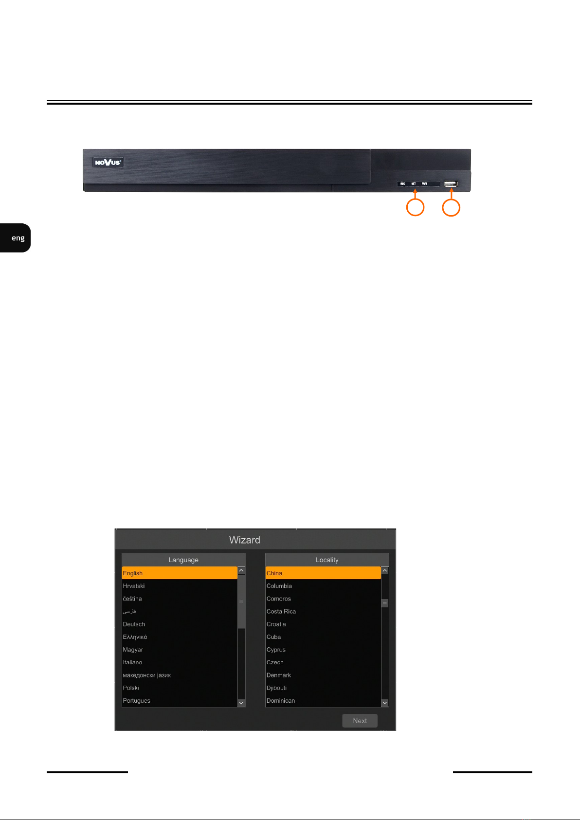
OSD languages: Polish, English, others
Control PC mouse and IR remote controller (in-set included), network
System Diagnostic automatic control of: HDDs, network, camera connection loss
Security password protection, IP filtering, MAC filtering
Installation parameters
Dimensions (mm) 380 (W) x 53 (H) x 268 (D)
Weight 1.5 kg (without HDD)
Power Supply 12 VDC (100 ~ 240 VAC/12 VDC PSU in-set included)
Power Consumption 40 W (with 2 HDDs)
Operating Temperature -10°C ~ 50°C
RACK Mount 19" 1U

NVR-6232-H2/F User’s manual (Short) ver.1.0
All rights reserved © AAT Systemy Bezpieczeństwa sp. z o.o.
4
FOREWORD INFORMATION
1.2. Main characteristics
• Supports up to 32 video channels without face recognition enabled or up to 16 video channels
with face recognition enabled
• Supports resolution up to 3840 x 2160
• Supported protocols: ONVIF
• Recording up to 3840 x 2160
• Recorded stream size up to 192 Mb/s in total from all cameras
• Fishsye camera support
• Face detection functions
• Internal HDDs mount up to 2
• 1 x Ethernet - RJ-45, 10/100/1000 Mbit/s
WARNING!
ONVIF protocol support was verified with IP cameras based on ONVIF ver. 2.2 and compatible
with the "PROFILE S".
Implementation of the ONVIF protocol by different manufacturers may vary by some functions,
which can make them work improperly or not in accordance with expectation. AAT SYSTEMY
BEZPIECZEŃSTWA SP. Z O.O. is not responsible for incompatibility problems resulting from
cameras of other brands than NOVUS, which are using ONVIF protocol. If you are using
ONVIF protocol cameras other than NOVUS brand it is recommended to test each time whether
required functions work correctly.
1.3. Package contents
Unpack the device carefully. After unpacking, please ensure that package contains the following items:
• Network Video Recorder
• USB Mouse
• Remote control
• User’s manual (short)
• Screws for fastening the disks
• RACK mountings
If any of the elements has been damaged during transport, pack all the elements back into the original
packaging and contact your supplier.

NVR-6232-H2/F User’s manual (Short) ver.1.0
All rights reserved © AAT Systemy Bezpieczeństwa sp. z o.o.
5
STARTING THE DEVICE
2. STARTING THE DEVICE
2.1 Electrical connection and other back panel elements.
NVR-6232-H2/F
1. CONNECTORS : Block of alarm input/output connectors
2. AUDIO IN: Audio mono inputs to connect microphones.
3. VGA: VGA connector, to connect VGA monitor
4. HDMI: HDMI connector, use the HDMI cable to connect monitor
5. USB: USB port for external Flash memory and other USB devices.
6. LAN: RJ-45 connector port to connect to the local network and internet.
7. POWER SOCKET: To plug in the 12V power.
8. AUDIO OUT : Audio output
8
1
3
2
4
5
6
7

NVR-6232-H2/F User’s manual (Short) ver.1.0
All rights reserved © AAT Systemy Bezpieczeństwa sp. z o.o.
6
STARTING THE DEVICE
2.2 HDD mounting
Novus NVR-6232-H2/F supports up to 2 internal SATA HDDs.
WARNING!
In order to find information regarding the compatible models of HDDs and their maximum
capacities, please contact Novus distributor or check the information presented at
www.novuscctv.com. AAT SYSTEMY BEZPIECZEŃSTWA SP. Z O.O. is not responsible for
any problems from using not recommended hard drives.
The list of compatible HDDs contains all the HDDs that can be used with a given DVR including
HDDs designed for office use - so called desktop disks. However, due to the fact that reliability of
the recording process and data safety are paramount factors of any CCTV system, we strongly
advise to use HDDs designed for continuous (24/7) operation.
You need to format disks if they were used in a different device. All data saved on HDD prior to
format will be lost.
HDDs Installation
To install the hard disks, unscrew 3 screws on the back of the casing (pointed by arrows), sliding top
cover backwards and then lifting it up.
WARNING: !
Before removing cover unplug the power cord from the NVR. When NVR is turned on before
disconnecting the power cord, shut down the recorder using the NVR menu.
If you use the disk previously used in another device, it is necessary to format it before using.
Formatting the drive erase all the data from disk. All drives in the recorder should be exactly the
same type.
By default, SATA cables are packed together with DVR accessories, while HDD power cable is
connected to the NVR PSU and ready for connecting the HDDs.
After removing the housing, unscrew and remove the upper and lower mounting strip for disks by
unscrewing the screws on the side of the recorder housing. Then, mount the drives using the mounting
screws included with the recorder.
CAUTION!
If the device was brought from a location with lower temperature, please wait until it reaches the
temperature of location it is currently in. Turning the device on immediately after bringing it from a
location with lower ambient temperature is forbidden, as the condensing water vapour may cause short-
circuits and damage the device as a result.

NVR-6232-H2/F User’s manual (Short) ver.1.0
All rights reserved © AAT Systemy Bezpieczeństwa sp. z o.o.
7
STARTING THE DEVICE
After removing the housing, mount the disk or disks using the mounting screws (4 pieces per disk). The
drives should be screwed in the places marked in the picture below
After screwing the disks, connect the signal and power cables between the disk and the recorder main
board.
2.3. Connecting the power supply.
Please connect provided power cord in the rear power port of the NVR like described
below.Initialization lasts approximately 60 seconds. During this time executing any device functions
and pressing any buttons is prohibited. To shut down the device please use the menu.
CAUTION:
Make connection when the power is not applied and the power switch is turned off.
Do not place the power cord under the carpet or rug. The power cord is usually earth-grounded.
However, even if it's not earth-grounded, never modify it on your own for earth-grounding.
Make sure that power adapter is placed near of NVR and secured from accidental disconnection.
If the device was brought from a location with lower temperature, please wait until it reaches the
temperature of location it is currently in. Turning the device on immediately after bringing it from a
location with lower ambient temperature is forbidden, as the condensing water vapour may cause short-
circuits and damage the device as a result.
Before starting the device familiarize yourself with the description and the role of particular inputs,
outputs and adjusting elements that the device is equipped with.

NVR-6232-H2/F User’s manual (Short) ver.1.0
All rights reserved © AAT Systemy Bezpieczeństwa sp. z o.o.
8
2.4. Connecting monitor
This product supports following interfaces for main monitor: HDMI, VGA.
For HDMI following resolutions are supported: 1280x1024, 1920x1080 i 3840x2160.
2.5. Connecting camera and Network
NVR-6232-H2/F need external network switch for connecting cameras. Please notice that the
Ethernet connection is effective within 100 meter distance. To connect IP cameras please connect
cables like on image and follow the described below.
We recommend that you configure the camera before connecting to a recorder, as described the
manual camera. Please note that cameras have addressed the unique IP address supported by the
recorder.
Connecting cameras and network recorders NVR-6232-H2/F
2.6. Connecting external devices
• Connecting audio ports
Audio output signal normally are above 200mV @1kΩ load. You can connect to it the audio amplifier
with the external speakers.
• Connecting USB devices
NVR has 1 x USB 2.0 port on front and one 1 x 3.0 USB port on back panel. They could be used for
connecting external Flash memory, mouse connection and other USB compatible devices. To connect
storage memory it is recommended to use port USB 3.0
STARTING THE DEVICE
NOVUS NVR
INTERNET PC
COMPUTER
IP CAMERAS 1-32
NETWORK SWITCH

NVR-6232-H2/F User’s manual (Short) ver.1.0
All rights reserved © AAT Systemy Bezpieczeństwa sp. z o.o.
9
• Connecting alarms ports
The NVR-6232-H2/F network recorder has alarm inputs and outputs. The alarm inputs are marked in
the ALARM-IN section. The individual inputs should be connected as shown in the figure below:
An example of connecting the alarm output no. 1 should be done as shown below:
STARTING THE DEVICE
NO COM ALARM
Power
source
GND
Alarm in
Alarm out
RS485
ALARM
IN1 IN2 IN3 IN4 GND
CZUJNIK

NVR-6232-H2/F User’s manual (Short) ver.1.0
All rights reserved © AAT Systemy Bezpieczeństwa sp. z o.o.
10
NVR OPERATING
3. NVR OPERATING
3.1. Front panel description
1. LED LEDs for monitoring NVR activity.
- REC - monitors recording activity
- NET - monitors networking activity
- PWR - activities when power is on
2. USB PORT USB 2.0 port for external Flash memory and mouse connection.
3.2. Controlling via USB mouse
It is possible to control NVR via an USB mouse connected to the USB port. Double-click on any
camera in split screen display mode switches the display to full-screen mode. Subsequent double-click
returns to previous display mode. Move cursor to the top or click the right key of mouse to bring up
MAIN MENU and select START icon.
Certain positions allow to select them via mouse scroll. Depending on NVR operating mode, pressing
RMB displays a corresponding function menu.
3.3. First start
After the NVR is started for the first time, a window is displayed that allows you to select the language
used in the menu (left-hand window) and device location in (right-hand window). Clicking the left
mouse button in one of the windows changes the settings. To select the English language, select
ENGLISH in the left-hand window and select the recorder location in the right-hand window.
To go to the next menu, click the NEXT button.
1
2

NVR-6232-H2/F User’s manual (Short) ver.1.0
All rights reserved © AAT Systemy Bezpieczeństwa sp. z o.o.
11
The next wizard window allows you to set time parameters such as TIME ZONE, SYSTEM TIME,
DATE FORMAT, TIME FORMAT, DST, SYNCHRONOUS, NTP SERVER and VIDEO FORMAT.
After making your selection, click the NEXT button. You must change the password in the password
change wizard. The password must be at least 8 characters long. It should contain a number, and upper
and lower case letters. Enter them on the screen keyboard available after clicking in the NEW
PASSWORD and CONFIRM PASSWORD fields.
To display the entered password, check the DISPLAY PASSWORD box. Selecting LOG IN
AUTOMATIC field will automatically log the user into the system after starting the recorder.
By selecting the ENABLE field in the PATTERN LOCK row, it is possible to activate the setting of
enabling access for the user by means of a graphic pattern instead of entering the password. To start
the graphic symbol settings, click the EDIT button. Then, holding down the left mouse button, move
the cursor between the displayed circles twice to mark the pattern that will be used to unlock the
device.
NVR OPERATING

NVR-6232-H2/F User’s manual (Short) ver.1.0
All rights reserved © AAT Systemy Bezpieczeństwa sp. z o.o.
12
After clicking on the NEXT button, a window is displayed that allows you to set a set of questions and
answers that can unlock access to the recorder.
To add a question, click on the QUESTION field to enter the question using the keyboard. Then click
on the ANSWER field to enter the answer to the question. Clicking on the ADD button adds a set of
questions and answers. Clicking the NEXT button takes you to the window in which information about
the disk connected to the recorder is displayed.
NVR OPERATING

NVR-6232-H2/F User’s manual (Short) ver.1.0
All rights reserved © AAT Systemy Bezpieczeństwa sp. z o.o.
13
If the STATUS field displays information about the inaccessibility of the disk, format the disk by
clicking on the FORMAT button. A window appears asking you to confirm that you want to format
the disk.
NOTE: Formatting causes the loss of information stored on the hard drive.
Pressing the OK button confirms the intention to format the disk.
The status of the disk should be "READ AND WRITE" after successful formatting.
NVR OPERATING

NVR-6232-H2/F User’s manual (Short) ver.1.0
All rights reserved © AAT Systemy Bezpieczeństwa sp. z o.o.
14
3.4. Startup configuration
Prior to using NVR for the first time, initial setup is strongly advised. Before you connect the IP
cameras to the NVR, please set up network and stream parameters of IP cameras in the right way.
Note:
For suggested values for IP camera setting please refer to the “Cameras Capability Table” available
on the www.novuscctv.com website. If you set wrong values some problems may appear: the NVR
cannot search the IP camera, the stream cannot be connected, the image is not fluent, the image quality
is bad and so on.
In case of first NVR start WIZARD SETUP menu window occurs (if function wasn’t disabled earlier).
To configure NVR please follow procedure like below, after finishing all the steps NVR is ready to
work:
NVR OPERATING

NVR-6232-H2/F User’s manual (Short) ver.1.0
All rights reserved © AAT Systemy Bezpieczeństwa sp. z o.o.
15
I. NETWORK SETTINGS : By default, the recorder has the download of the IP address and DNS
settings from the DHCP server enabled. If retrieving the address fails, the DVR is available at
192.168.1.100 with a subnet mask of 255.255.255.0. In the menu displayed, you can change the
settings after unchecking the OBTAIN AN IP ADDRESS AUTONOMATICALY and OBTAIN DNS
AUTOMATICALLY boxes. The following network settings of the recorder are available: IP (Subnet
Mask. When it is necessary to connect the NVR to the Internet (for remote access, sending e-mails,
etc.), configure the following parameters: GATEWAY, PRIMARY, SECONDARY DNS.
It is possible to change the default HTTP port for displaying the device's web panel as well as the
SERVER PORT and HTTPS data transfer ports. Changes to parameters should be confirmed with the
NEXT button
NVR OPERATING

NVR-6232-H2/F User’s manual (Short) ver.1.0
All rights reserved © AAT Systemy Bezpieczeństwa sp. z o.o.
16
II. ADD CAMERA: Allows you to configure the camera and add them to the recorder. Upper window
displays cameras discovered by the NVR. To change the addressable cameras, click on the icon in
the column EDIT (This works with cameras NOVUS IP 6000 series).
Enter the address in the IP ADDRESS field and set the masks in the SUBNET MASK, then press the
OK button to save the settings.
Press the button to add a camera to the system.
Added camera is displayed on the bottom of the menu list. To edit the connection settings of the
camera, press the EDIT column.
NVR OPERATING

NVR-6232-H2/F User’s manual (Short) ver.1.0
All rights reserved © AAT Systemy Bezpieczeństwa sp. z o.o.
17
If you are having problems connecting to the camera, you must enter the correct user name in the
USER NAME and password in the PASSWORD field and then press the OK button to save the
settings. If the NVR connected to the camera in STATUS filed will be displayed “Connected”. To
remove a camera from the list, press the in DELETE column.
III.RECORD SETTINGS :
NVR OPERATING

NVR-6232-H2/F User’s manual (Short) ver.1.0
All rights reserved © AAT Systemy Bezpieczeństwa sp. z o.o.
18
You can set one of the modes:
- MANUAL RECORD SETTINGS - You can set the recording time from the moment you select the
manual recording in range from 1 minute to 1 hour or manually off recording.
AUTO - set all the cameras on one of the following modes :
- MOTION RECORD - starts recording after receiving motion detection information from the camera.
- SENSOR RECORD - starts recording after alarm generated on alarm input
- MOTION RECORD + SENSOR RECORD - starts recording after motion detecion alarm and after
alarm from alarm inputs
- ALWAYS(24x7) RECORD + MOTION RECORD - continuous recording and recording after
receiving motion detection information from the camera.
- ALWAYS(24x7) RECORD + SENSOR RECORD - continuous recording and recording alarm
generated on alarm input
- ALWAYS(24x7) RECORD + MOTION RECORD + SENSOR RECORD - continuous recording
and recording alarm generated on alarm input and after receiving motion detection information from
the camera.
- ALWAYS(24x7) RECORD + MOTION RECORD + SENSOR RECORD + AI RECORD -
continuous recording and recording alarm generated on alarm input, motion detection information and
after receiving Intelligence Analysis from the camera.
IV. QR CODES : This menu allows you to scan a QRcode in the Supelive plus application or enter a
device code to autonat.com site. The service allows you to connect to a device connected to the Internet
network behind a router equipped with NAT.
NVR OPERATING
Device code QR Code Security Code

NVR-6232-H2/F User’s manual (Short) ver.1.0
All rights reserved © AAT Systemy Bezpieczeństwa sp. z o.o.
19
This panel allows you to scan the QR code in the SuperLive Plus application or enter the device code
on autonat.com to connect to a device connected to the Internet behind a NAT-equipped router. To add
devices to the list of devices associated with the account in the mobile application, use the security
code displayed after cliking on the button.
In the ACCESS TYPE field, you can select the type of P2P service to be used by the device. It is
recommended to leave the NAT 2.0 setting. This service offers greater security by encrypting
connections between the NVR and the P2P server.
Note! The AAT SYSTEMY BEZPIECZEŃSTWA Sp. z o.o. company constantly cares for the
proper functioning of the P2P service, however, due to the use of third party infrastructure, it
cannot be held responsible for interruptions and inconveniences in the operation of the
service.
V. CLOUD UPGRADE:
In this panel you can start updating the device from the cloud. This option is only available if NAT 2.0
is selected for P2P connections. The current version of the software installed in the NVR is displayed in
the CURRENT VERSION field. To start the update, select the CLOUD UPDATE box and press the
OK button to save the settings and close the wizard.
NVR OPERATING

NVR-6232-H2/F User’s manual (Short) ver.1.0
All rights reserved © AAT Systemy Bezpieczeństwa sp. z o.o.
20
4. NVR MENU
4.1. Live monitoring
NOVUS network video recorders features a multilingual OSD menu allowing to adjust the settings of
the device. Available languages are: English, Polish, and others
As soon as the NVR completes its initialization process, it will enter the real-time monitoring image.
Displaying all cameras simultaneously is the default mode. On the bottom of screen STATUS BAR is
displayed.
To start access to the NVR click on the button to launch the start menu.
After clicking log on to the system (the default password for the root user is a pass).
STATUS BAR description:
NVR MENU
MENU BAR
VIDEO WINDOW
VIEW MENU
START MENU
Item Icon Description
Intelligent
Analytics Sarts the image analysis menu
Search and Backup Starts search and backup
Playback Launches the playback menu with the
displayed channels
Table of contents
Languages:
Other Novus Tuner manuals