Now Technologies Gyroset Link User manual

© 2018 Now Technologies Ltd. All rights reserved.
Now Technologies, the Now Technologies logo, and the GyroSet Glory are trademarks
of Now Technologies Ltd., registered in 18. Reáltanoda street, Budapest, 1053 Hungary.
European representative of the Manufacturer:
Now Technologies Ltd., 18. Reáltanoda street, Budapest, 1053 Hungary
www.nowtech.hu
GYROSET LINK
MANUAL
Document identier: NOW.Q.CE.M.EN–GL–0002–01
Revision: 01
Date of issue: 01 February 2019
1

2

Preliminary
Please review the user manual - this guide and the interactive Help - before
using GyroSet Link. To view the Help in the Glory Tools application, click on the
question mark icon in the upper right corner.
Information contained in this publication regarding device applications and the
like is provided only for your convenience and may be superseded by updates. It is
your responsibility to ensure that your application meets with your specications.
NOW TECHNOLOGIES MAKES NO REPRESENTATIONS OR WARRANTIES OF ANY KIND
WHETHER EXPRESS OR IMPLIED, WRITTEN OR ORAL, STATUTORY OR OTHERWISE,
RELATED TO THE INFORMATION, INCLUDING BUT NOT LIMITED TO ITS CONDITION,
QUALITY, PERFORMANCE, MERCHANTABILITY OR FITNESS FOR PURPOSE. Now
Technologies disclaims all liability arising from this information and its use. Use of
Now Technologies devices in life support and/or safety applications is entirely at
the buyer’s risk, and the buyer agrees to defend, indemnify and hold harmless Now
Technologies from any and all damages, claims, suits, or expenses resulting from
such use. No licenses are conveyed, implicitly or otherwise, under any Now Technol-
ogies intellectual property rights.
The Now Technologies and GyroSet logo are registered trademarks of Now Technol-
ogies Ltd.
It is our intention to provide our valued customers with the best documentation pos-
sible to ensure successful use of your Now Technologies products. To this end, we
will continue to improve our publications to better suit your needs. Our publications
will be rened and enhanced as new volumes and updates are introduced. If you
have any questions or comments regarding this publication, please contact our Help
Desk via E-mail at info@nowtech.hu. We welcome your feedback.
This document must be read and understood by the healthcare professional who is
installing and conguring the GyroSet Link and PGDT Omni.
3

MEDICAL DEVICE INTERFERENCE
GyroSet Link contains an IEEE 802.15.4 Standard compliant 2.4 GHz RF transceiver
that emits electromagnetic radiation. This electromagnetic radiation may interfere
with pacemakers, debrillators, or other medical devices. Maintain a safe distance of
separation between your medical device and the GyroSet Link. Consult your physician
and medical device manufacturer for information specic to your medical device. If
you suspect your GyroSet Link is interfering with your pacemaker, debrillator, or any
other medical device, stop using GyroSet Link.
Now Technologies Ltd. hereby declares that this wireless device is in compliance with
the essential requirements and other relevant provisions of the RED Directive and
Radio Equipment Directive 2014/53/EU, as applicable.
WARRANTY
Now Technologies Ltd. provides one year’s full warranty on the products. This warran-
ty covers any defects in materials or workmanship, with the exceptions stated below:
Faults resulting from the installation by an unqualied person. Any problem that is
caused by abuse, misuse, extreme water damage or extreme weather are not covered.
Also, consequential and incidental damages are not recoverable under this warranty.
MEDICAL DEVICE INTERFERENCE
GyroSet Glory contains components and radios that emit electromagnetic radiation.
This electromagnetic radiation – although unlikely - may interfere with pacemakers,
debrillators, or other medical devices. Maintain a safe distance of separation be-
tween your medical device and the GyroSet Glory. Consult your physician and medical
device manufacturer for information specic to your medical device. If you suspect
your GyroSet Glory is interfering with your pacemaker, debrillator, or any other medi-
cal device, stop using GyroSet Glory.
4

GyroSet Link installation instructions
GyroSet Link enables GyroSet Glory users to use their headset on a PGDT Omni or IOM
equipped wheelchair as a specialty input device (SID). The Omni is a universal specialty
controls interface that accepts signals from many dierent types of SIDs and translates
them into commands compatible with the PG Drives Technology R-net control system.
Before proceeding please make sure that one of the compatible devices are already
installed on the chair and working properly. For more information on how to set-
up the Omni please follow the instructions of R-NET OMNI TECHNICAL MANUAL
SK78813/7. It is possible to set up a control system so that it is unsuitable for some
users or even some vehicles. Although this guide contains recommended settings for
Omni for all of the above reasons it is important that you contact PG Drives Technol-
ogy if you have the slightest doubt or if you need any advice on programming.
5

Mounting
The GyroSet Link enclosure has two M4 sized screw threads on the back of the device
that is designed specically for mounting. As every vehicle and user is unique there
is no general mounting bracket available.
Dimensions and position of mounting points
6

Please make sure that the physical mounting meets the following criteria:
• Mounting should be removable as calibration of the sensors may be required from
time to time.
• Mounting shall be solid to minimise vibration eects between the chair and the
GyroSet Link unit. Vibrations and orientation of the chair are processed by the onboard
inertial sensors and it is mandatory that these measurements represent the movement
of the chair and not the movement of the mounting bracket on the chair.
• Non elastic mounting material is highly recommended, please avoid use of velcro or
any other temporary tapes or cable ties.
• To take advantage of the IP34 protection of the casing, cables must face the ground
to prevent rain from falling into the connector:
• When there is no intention to use the wired interface please leave the connector’s
silicon cap in place.
• Placement shall avoid the closeness of any magnetic materials or large iron parts as
they aect the orientation initialisation process and prevent the sensors to nd the
true magnetic north.
• Magnetic materials such as active magnets shall be avoided, magnetic noise shall
be less than 10μT.
• Electromagnetic components such as motors, relays, actuators must be at a
distance where magnetic noise is less than 10μT.
• Ferromagnetic components such as wheelchair frame must be at a distance
where their hard iron eect is minimal, usually more than 50mm depending on
the composition of the frame.
• Placement shall allow the GyroSet Link a clear radio connection with the GyroSet
Glory headset, that practically means:
• A clear line of sight between the GyroSet Link and the GyroSet Glory headset
must be provided.
7
• Devices that may produce radio interference, such as Smartphones, Pagers, Bluetooth
devices must be kept out of the way and placed in a distance from the GyroSet Link.
• Large metal surfaces that may deect radio signal must be placed relative to the
GyroSet Link so that they don’t block the signal.
• Placement is also important when wired connection is used, the distance between
the headset and the GyroSet Link must be less than the length of the standard cable
provided. (1.2m)
• Mounting should in no way cause the connectors to tense or slip out. (In case of
cables slipping out the GyroSet Link will automatically initiate radio connection.)
• The connector interface for the headset data cable must be accessible to allow
the caretaker to plug in or out the cable.
• GyroSet Link should be placed as such that the Status LED (logo) is visible for at least
the caretaker, preferably for the user as well.
• GyroSet Link’s mode selection touch interface (touch button with the logo) must be
accessible for the caretaker.
• Devices that may produce high capacity charges, such as ionisators must be at a
safe distance from the touch interface to avoid accidental activation.
• The audible feedback of the GyroSet Link is of high importance for the user, placement
should avoid blocking of the speaker.
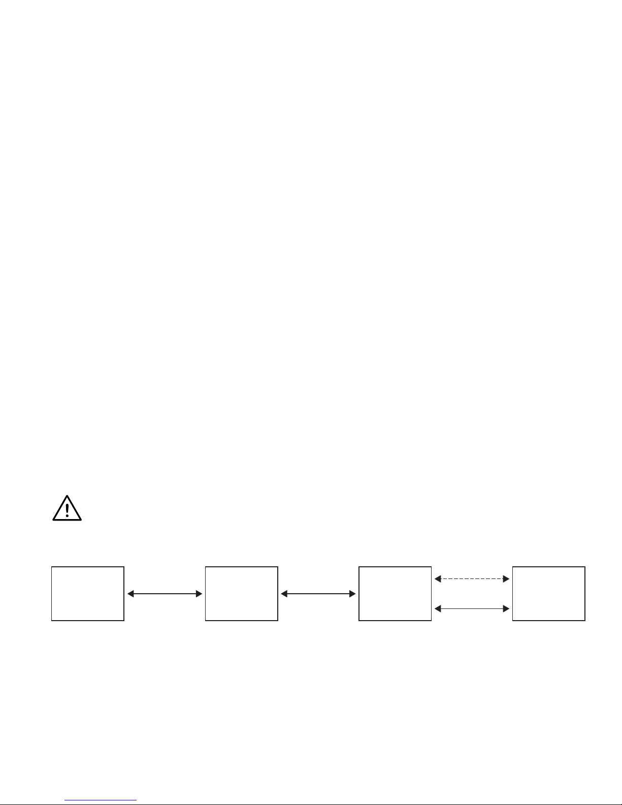
Power Module Omni GyroSet Link Glory Headset
Wireless
SIDR-Net
Wired
WARNING Protection against water according to IP34 is guaranteed only in case the Link has been
installed in a vertical position.
Wiring
Dimensions and position of mounting points
8

The GyroSet Link provides a proportional analogue signal compatible with PGDT
Omni. The interface is the standard D-type connector, tted with “detect link” and
“fth switch” functions. As there is no internal power source or auxiliary power input
connector on the GyroSet Link the power for operation is provided by the Omni.
The limitation of Omni’s power output is 12V and 100mA distributed between the two SID
connectors and the GyroSet Link consumes about 60-90mA typically when turned on.
Please make sure that there is no other device connected to the Omni that would
surpass the power limitation and prevent the system from operation.
For the above reason if the Omni is congured with programmable parameter “Sleep
12V” to cut the power on SID connectors when turned o, GyroSet Link is going to
be turned o as well. GyroSet Link doesn’t require a permanent power supply. For
power saving reasons “Sleep 12V” parameter is advised to be set.
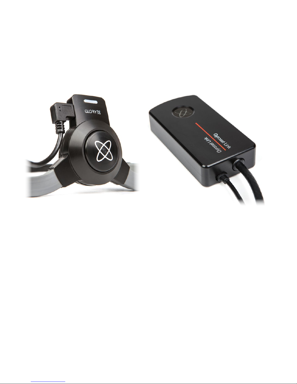
On the GyroSet Link there are two connector interfaces. One of which is an integrated cable
with D-type connector on it to control the Omni (referred to as Omni cable) and another oval
shaped interface to connect the GyroSet Glory cable into (referred to as Data cable).
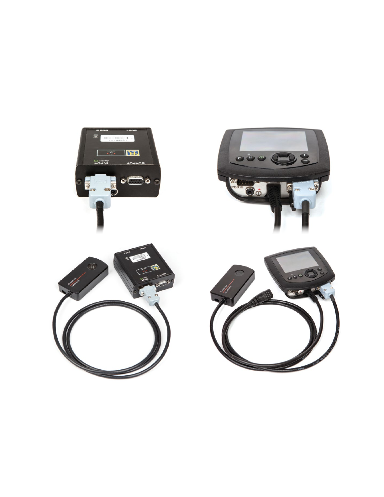
The two interfaces of the GyroSet Link
(on the left the oval shaped data connector)
Omni Port-1 D-type connector
9
The preferred SID port if there is only one input device connected to the Omni is Port
1 as shown on the picture below. In case of PGDT IOM there is only one INPUT port
where the D-type connector can be connected:
Connecting the GyroSet Link to Omni Connecting the GyroSet Link to IOM
10
In case of use of a wired GyroSet Glory to GyroSet Link connection please use the stan-
dard cable provided with the headset. The shape of the connectors are designed so that
they seal the interfaces from water and are not interchangeable with each other:
Connecting the Data cable to the GyroSet Link Connecting the Data cable to the GyroSet Glory
Please make sure that the wiring meets the following criteria:
• The GyroSet Link must be properly connected to PGDT Omni or IOM:
• Cable that connects to the wheelchair controller must be secured with screws.
• Cable that connects to the wheelchair must be tightened to the frame to avoid
accidental crushing by the movement of actuators.
• Cable placement shall not allow accidental crushing if the wheelchair hits an
obstacle.
• The analogue connector should be connected to Omni Port-1 or IOM INPUT only.
11

In case the D-type connector has become disconnected a screen will appear on the Omni
with error code 0905:
WARNING Always make sure that the chair is congured in a way that the chair’s on/o switch is
available to the user, according to the manufacturer’s guidance.
12

Setting up the Omni and the GyroSet Link
Pleas nd our tutorial videos on https://www.nowtech.hu/tutorials/
Gyroset Link enables Gyroset Glory users to use their headset on a PGDT Omni or
IOM equipped wheelchair as a specialty input device (SID). The Omni is a universal
specialty controls interface that accepts signals from many dierent types of SIDs
and translates them into commands compatible with the PG Drives Technology R-net
control system.
PROGRAMMING THE OMNI
For programming the Omni please follow the instructions provided by Penny and Giles
Drive Technologies. There are three methods of programming the Omni. Details of
the actual programmable parameters are given in the SK78813 Programming chapter.
Ensure the R-net Control System’s Drive, Acceleration and Deceleration settings are at
a comfortable and safe level prior to attempting to program the Omni to suit the user.
Refer to the R-net Technical Manual SK77981 or the On-Board Programming Manual
SK78571 for details of how to program the R-net Control System. Programming should
only be conducted by professionals with in-depth knowledge of PG Drives Technology
electronic control systems. Incorrect programming could result in an unsafe set-up
of a wheelchair for a user. Now Technologies Ltd. accepts no liability for losses of any
kind if these conditions are not met.
13

Using the R-Net PC programmer to congure Omni, Port 1 SID has to be set to propor-
tional. To use the Click sensor of the headset to activate menu functions on the Omni,
Port 1 User control has to be set to Menu and Return To Drive.
14

WARNING
The Omni can be put to sleep by selecting that option in the User Menu. To awaken the
Omni, the following SID sequence is required: Left, Right, Left, Right. Note, this waking
method only works if the Omni has been put to sleep via the User Menu. For that to
work “Sleep 12V” parameter has to be turned o to allow the GyroSet Link to operate
constantly. For a more safe operation of the chair Now Technologies doesn’t recommend
the above described scenario, rather please install a separate User button in the reach
of the User that can act as an emergency stop as well.
Please make sure that your R-Net conguration meets the following criteria:
• The correct SID port is congured as proportional.
• Sleep 12V parameter is set.
• User control is set.
• Drive, Acceleration and Deceleration settings are at a comfortable and safe level.
GYROSET LINK CONFIGURATION
In this document we presume that the user is already familiar with the usage of the
GyroSet Glory headset, for detailed instructions on how to use the headset please
follow the Headset’s User’s Manual.
The GyroSet Link translates the user’s head movements into analogue joystick
sweeps. For that to function correctly all GyroSet Link parameters must be set
according to the individual user’s needs. The conguration of the GyroSet Link can be
achieved through the Glory Tools application - available for all users - that provides
an interactive Help and settings Wizard, which you can nd by clicking on the question
mark icon in the top right corner of the application of any page. The headset can
measure tilting of the head in the four main directions, forward, backward, left
and right.
15

Using the head drive function
PREPARATIONS
1. Find a comfortable seating position for the user and adjust the headrest so that
is always in the reach with the headset’s mode button. It is recommended that
there is a distance of 3-5 cm between the headset’s button and the headrest.
2. Turn on the headset, and place it on the user’s head, adjust the click sensor’s
exible tube as described in Headset User’s Manual. The sensor should be placed
approximately 1 cm from the movable part of the user’s face (corner of the eye,
cheek, corner of the mouth etc.)
3. Turn on the Omni.
4. Select drive mode on the headset by a long press on the mode button.
DRIVING
1. Imagine that Your head will act like a regular joystick.
2. Press the headset’s mode button shortly against the headrest then return Your
head into a neutral position and keep it there until the countdown stops. This is
necessary to measure Your personal neutral position and enables You to change
the position from time to time.
3. The countdown will start, GyroSet Link will mark every second with a beep. Control
starts when the countdown is at zero, marked with higher and longer beep tone.
4. Tilt your head to the direction You wish to go. The amount of tilt is proportional to
the speed of the wheelchairs movement.
5. To come to a halt, move your head into the neutral position (into the dead-zone)
6. To stop driving press the headset’s mode button against the headrest.
For each control session any new neutral position can be selected.
16

USING THE OMNI MENU
1. When the chair is not moving the headset’s click sensor can be used to enter to the
Omni Menu.
2. Press the headset’s mode button shortly against the headrest to activate naviga-
tion through the Omni Menu
3. Your head will act as joystick to help You go through all the available preferences.
4. Select menu items with tilting Yout head right, like as a joystick
5. Press the headset’s mode button shortly against the headrest to deactivate menu
navigation
6. Use headset’s click sensor to exit Omni Menu
Please make sure that the following criteria are met before trying to drive the wheel-
chair with the GyroSet Link:
• Understanding of the intended use of the headset by getting familiar with the
GyroSet Glory Headset’s User Manual
• The adjustment of the headrest:
• The User must be able to reach the headrest with the headset’s mode button at
any times.
• Inertial sensors of the headset must be calibrated with Glory Tools
• Intended direction of movement must be set with Glory Tools
• Range of head movement must be set with Glory Tools
• Faint detection threshold must be set out of operation range with Glory Tools
• Tremor lter must be set with Glory Tools
• Click sensor functions and parameters must be set with Glory Tools.
• Click sensor long press maximal timeout must be set with Glory Tools.
17

• Centre mode and parameters must be set with Glory Tools:
• If the centre mode is on a countdown, timeout has to be set.
• The maximum speed, acceleration, deceleration of the head drive prole of the
wheelchair controller must be adjusted:
• Settings of the PGDT controller must be administered by PGDT trained and
authorised personnel.
• Acceleration and deceleration of the wheelchair shall not cause an inertia on the
users head that the user cannot compensate.
• Maximum speed must be always in correlation with the local regulations.
• The GyroSet Link shall be paired with the Users Personal Area Network.
• User password of the Personal Area Network must be changed frequently.
• The password must be chosen carefully, it should contain lower and upper case
letters, symbols and numbers.
• The password must be minimum 8, ideally 16 characters long.
• Service network must be used only for the time when changes are made to the
personal drive prole.
• The wheelchair can be driven in Service mode to allow ne tuning of the parame-
ters but Service mode shall not be used for regular drive.
• User network protected with users unique password is more safe and doesn’t
allow parameter settings online.
• The user should avoid:
• Environments with extreme radio interference when controlling the Link with the
headset wirelessly.
• Environments of extreme magnetic elds, such as MRI because these can dam-
age the onboard sensors.
• The user shall be aware
18

• The usage of the headset’s mode button.
• That the GyroSet Link must be selected for control with the headset.
• The mode of centre detection.
• If the mode is on a countdown, the user shall be motionless in a neutral
position after activating the drive function.
• That the headset acts as a joystick on the R-Net:
• By programming the wheelchair controller, various functions can be tied to
“fth button” presses.
• When fth button’s long press timeout is set smaller on the R-Net than on
the GyroSet Link the click sensor can turn the chair into sleep mode
• When fth button function is programmed so that the User can access
menus the headset will navigate.
• When fth button function is programmed so that the User can control
actuators the headset will control.
• If the GyroSet Link is mounted to a part that stays in level when the
backrest is tilting it won’t be able to compensate the change.
• The GyroSet Link measures the head orientation relative to the
GyroSet Link.
• Tilting of the backrest will cause a change in the orientation of the
User’s head and will have a feedback eect on the actuator.
• After the drive mode is initiated a distinguishable audible feedback can be heard.
• The chair will move according to the head movements and the prole settings
of the GyroSet Link and the R-Net controller.
• The chair will move as long as the function is deactivated or failure detected.
• That unpredictable changes in the environment can cause the sensors to drift
and change the behaviour of the chair
19

• If the centre of the head joystick is o when driving the user shall stop and
reinitiate drive.drive.
• That depletion of the headset’s battery will cause the chair to stop.
• A distinguishable audible feedback is given during headset turn on when the
charge reaches 30% of the headset’s battery.
• The headset’s battery must be charged on a daily basis.
• The falling of the headset will cause the chair to stop.
• A sudden backward movement of the head inside the turning dead zone will force
the system to execute an emergency break of the chair.
• If the Users head reaches the end of the range of operation the sweep of the
head joystick is at maximum.
• If the Users head reaches the safety zone the chair will stop.
• If the Users head is in the range of the dead zone the chair won’t move or
will stop.
• If the headset is in a forbidden orientation it will deactivate the function or won’t
activate the function:
• If the angle of headsets basis to the ground is more than 90 degrees in any
direction it will detect forbidden orientation.
• Upside-down corresponds to 180 degrees that is larger than 90 degrees.
• If the headset measures accelerations bigger than 1g it will deactivate the
function.
• Inertia that can not be compensated by healthy neck muscles will cause the
chair to stop.
20
Table of contents
Other Now Technologies Wheelchair manuals


Popular Wheelchair manuals by other brands

Liberator
Liberator SM8500 L owner's manual

Vela
Vela Blues 100 Mounting instructions

Invacare
Invacare Tracer SX5 Recliner Owner's operator and maintenance manual

Pride Mobility
Pride Mobility JAZZY 1103 owner's manual

Decon wheel
Decon wheel Mobilex Dolphin Assembly instructions

Handicare
Handicare Emineo user manual


