Vela Blues 100 User manual

VELA Blues 100, 210, 300 & 1100
MOUNTING INSTRUCTIONS EN
REGARDING:
Manual no. 105903
Lashing & docking kit

TABLE OF CONTENT
1.0. INTRODUCTION 3
1.1. SAFETY 4
1.2. WARRANTY 5
1.3. UNPACKING THE KIT 5
2.0. MOUNTING THE LASHING KIT 6
2.0.1. Mounting the lashing fitting, front 6
2.0.2. Mounting the tubular leg on C-rails 6
2.0.3. Mounting the rear securing fitting, folding armrest 6
2.0.3.1. Mounting the rear securing fitting, folding armrest
(VELA Blues 210) 6
2.1. LEG SUPPORT 7
2.0.4. Mounting the rear lashing fitting, fixed armrest 7
2.1.1. Resizing of hole in fitting for electric leg support 7
2.1.2. Screwing on the fitting 7
2.2. REPLACEMENT OF SCREWS AND BOLTS 8
2.1.3. Screws in leg support 8
2.2.1 Replacement of screws in the seat back frame 8
2.2.2. Replacement of bolts in the headrest 8
2.3. POSITION OF LABELS 9
3.0. ADVICE AND GUIDANCE 10
3.0.1. lashing down an electric wheel chair 10
3.0.2. Placement of 4-point seatbelts on the power chair 10
3.1. POSITIONING THE 3-POINT SEAT BELT ON THE USER 11
3.1.1. Wrong positioning of seatbelt 11
3.1.2. correct positioning of seatbelt 11
4.0. MOUNTING THE BASE PLATE AND LOCKING PLATE 12

3
DEAR CUSTOMER
We would like to thank you for purchasing a VELA
lashing & docking kit. This user manual contain useful
information about positioning, operating and mainten-
ance of the VELA lashing & docking kit.
Important
Please read this user manual thoroughly and keep
it for later use. This user manual must always
accompany this lashing & docking kit. The user
manual can also be found on VELA’s website: www.
vela.eu, where you also can find other relevant
information about VELA Blues and VELA Blues
accessories.
If you have any questions, please contact VELA’s
distributor in your country.
VELA reserves the right to make changes to this
manual.
VELA
Gøteborgvej 8-12
DK-9200 Aalborg
Denmark
www.vela.eu
1.0. INTRODUCTION

4
1.1. SAFETY
VELA Blues 100, 210, 300 & 1100
have been tested and meet the
requirements of DS/ISO 7176-19
and their use is thus permitted as a
passenger seat during transport in a
motor vehicle.
The electric wheelchair/user must
face in the direction of travel and be
harnessed with a 3-point seatbelt.
The wheelchair must be lashed in
place with 4-point belts.
The wheelchair must be clearly
marked with a hook-label at all four
anchor points.
For the VELA Blues 100, 210, 300 &
1100 to be used as a passenger seat
of a motor vehicle, the chair must
be configured as shown below:
:: Comfort seat and back system
(width 40x45 – 50 cm)
:: WB head restraint
:: Folding or fixed armrest
:: Electric or manual chair back
:: Electrically operated leg support
or E-leg support + swivel footrest
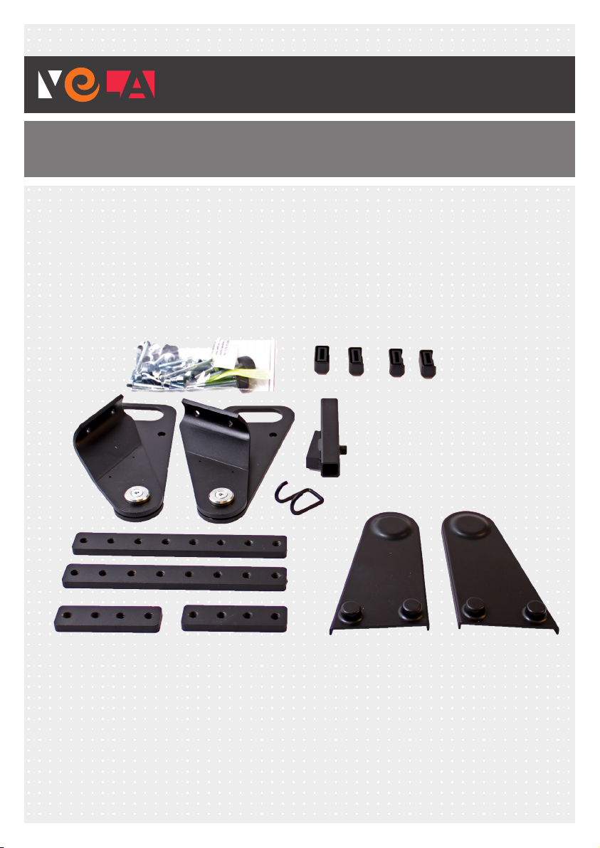
In addition to the above, the chair
must be accompanied by a lashing
kit. Two dierent types of lashing kit
are available; which one to use de-
pends on the type of arm rest fitted
to the chair.
These must be ordered from VELA.
Chair with folding armrest
Item number for lashing kit for fol-
ding armrest: 926376.
Chair with folding armrest
Item number for lashing kit for fixed
armrest: 926375.
Docking
VELA Blues 300 is also available for
Dahl Docking Station. The chair
must still be configured as for
4-point seat belts and the mounting
kit for docking must be mounted.
Item number for docking station
mounting kit: 926425.
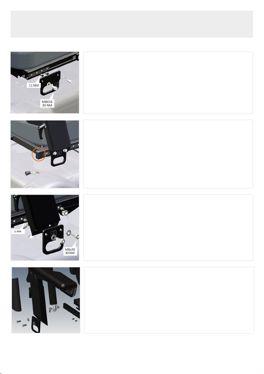
See section 2.0 re. mounting the
lashing kit
See section 3.0 re. correct mounting
of seat belts.
See section 4.0 re. mounting the
base plate and lock plate for the
Dahl Docking Station.
GENERAL

5
1.2. WARRANTY
VELA provides warranty by the laws
and regulations which are debt in the
country the chair is bought in. The
warranty only applies when using
original spare parts and accessories.
Modification may only be carried out
by authorised service technicians.
VELA does not accept responsibility
for damage or injury to the product
or user, which have arisen due to:
:: Transportation
:: Misuse
:: General wear and tear
:: Incorrect use
:: Use of non-original spare parts
and accessories
:: Adjustments carried out by
unauthorised service technicians
1.3. UNPACKING THE KIT
VELA lashing & docking kit is sup-
plied in cardboard packaging, de-
veloped with consideration for the
environment.
If there are any parts missing or
transport damage to the chair, plea-
se contact your dealer immediately.
Do not not try to repair any damage
or use the kit.
Content of the cardboard
packaging:
:: VELA Lashing kit
:: VELA Docking kit
:: This mounting instruction

6
2.0. MOUNTING THE LASHING KIT
2.0.3. MOUNTING THE REAR SECURING FITTING, FOLDING
ARMREST
First, fit the block with 8 threaded holes into the C-rail
and firmly tighten the 2 x pinol screws (11 NM), one of
them into the threaded hole hidden behind the armrest
and the other at own option. Then mount the lashing
fitting to the two holes in the bottom of the armrest with
washers and two M8x20 skruer screws (30 NM).
2.0.1. MOUNTING THE LASHING FITTING, FRONT
First, fit the block with four threaded holes in C-rail and 2
x screws are firmly tightened (11 NM) into the two middle
threaded holes. Then mount the securing fitting with
washers and two M8x16 screws (30 NM).
Note that the hook label must face the rear.
2.0.2. MOUNTING THE TUBULAR LEG ON CRAILS
A tubular leg is fitted at both ends of the C-rail on both
sides. The tubular leg must cover the sharp edges of the
C-profile in the event of the seatbelt slipping this far back
on sudden application of the brakes. The opening in the
side of the tubular leg faces inwards towards the seat.
2.0.3.1. MOUNTING THE REAR SECURING FITTING,
FOLDING ARMREST VELA BLUES 210
First, fit the block with 8 threaded holes into the C-rail
and firmly tighten the 2 x pinol screws (11 NM), one of
them into the first threaded hole and one in the second.
The first hole is used to fit the backrest angulation in.
Then mount the lashing fitting to the two holes in the
bottom of the armrest with washers and two M8x20
skruer screws (30 NM).

7
Mounting the edge covering
Lift the top of the armrest and push the edge covering
down over the part attached to the chair and then repla-
ce the upper part. This is done on both sides. The purpo-
se of the edge covering is to prevent sharp edges cutting
through the seatbelt in the event of sudden braking or a
collision.
2.0.4. MOUNTING THE REAR LASHING FITTING, FIXED
ARMREST
First, fit the block with 8 threaded holes into the C-rail,
then firmly tighten 2 x pinol screws (11 NM), one in the
threaded hole behind the armrest and the other at own
option. Then mount the seat back hinge with washers
and two M8x16 screws (30 NM). The plastic covering is
attached to the fitting with a small screw from behind.
2.1.1. RESIZING OF HOLE IN FITTING FOR ELECTRIC LEG
SUPPORT
The hole indicated must be enlarged to Ø8 for the las-
hing fitting to be screwed to the chair if it has an electric
leg support.
2.1.2. SCREWING ON THE FITTING
First, the threaded block must be fastenedinto the C-rail
with 2 x pinol screws (11 NM), after which the fitting is
screwed on (30 NM) together with the lashing fitting,
using 2 x M8x20 Allen screws with low profile heads,
without washers.
2.1. LEG SUPPORT
M8x20 Allen
screws 30 NM

M8x25
Stahlbolzen
8
2.2.2. REPLACEMENT OF BOLTS IN THE HEADREST
The existing screws are replaced with M8x25 steel bolts.
After adjustment to suit the user the bolts must be firmly
tightened.
2.1.3. SCREWS IN LEG SUPPORT
An M5 thread has to be cut into the base of the leg
support. To prevent the leg support falling o, a M5x65
screw is fitted into the leg support from below. The
screw must not be screwed so far in as to prevent the
leg support being lifted and turned to the side.
The screw must jut out approx. 30 mm at the bottom.
2.2.1 REPLACEMENT OF SCREWS IN THE SEAT BACK FRAME
The existing tightener is replaced by the above M8x35
screw and firmly tightened (30 NM).
M8x25
Steel bolt
2.2. REPLACEMENT OF SCREWS AND BOLTS

9
2.3. POSITION OF LABELS
Position of labels on fittings
Position of label on VELA Blues 100
Position of label on VELA Blues 210
Position of label on VELA Blues 300
Position of label on VELA Blues 1100

10
3.0. ADVICE AND GUIDANCE
3.0.1. LASHING DOWN AN ELECTRIC WHEEL CHAIR
When lashing down a wheelchair into a vehicle to be used as a passenger
seat, certain precautions apply to ensure that the wheelchair is lashed down as
safely as possible.
:: The chair must be set at its lowest position.
:: The seat must be moved into the horizontal position
:: The seat back must be adjusted to an angle of max. 10°
:: Electric wheelchairs must be switched o so that the automatic brake
comes on
Placement of 4-point seatbelts
Wieved from the side and from the front (see picture below)
3.0.2. PLACEMENT OF 4POINT SEATBELTS ON THE POWER
CHAIR
All four lashing points are labelled.
Viewed from the side
Rear straps Front straps

11
3.1. POSITIONING THE 3-POINT SEAT BELT ON THE USER
3.1.1. WRONG POSITIONING OF SEATBELT
Beware: The 3-point seat belt must not be tightened
across sharp edges. The drawing shows the incorrect
positioning of a 3-point seatbelt.
3.1.2. CORRECT POSITIONING OF SEATBELT
Beware: Seatbelts must not be held away from the body
by parts of the wheelchair, such as arm rests, wheels,
etc. The lap belt must be positioned as close as possible
to the hip joint. The seatbelt must have full contact with
the shoulder, chest and hips.

701.005 © Vermund Larsen A/S
VELA :: Gøteborgvej 8-12 :: 9200 Aalborg SV :: Denmark :: +45 96 34 76 00 :: [email protected] vela.eu
Before mounting the locking plate, screws no. 1, 2 and 3
are screwed into the base plate. Screws no. 2 and no. 3
are screwed into the outer tube and the column respec-
tively to fix them in place.
Base plate is mounted on the chassis using 4x
M8x40 button head scews fastened with M8 lock
nuts. The large apertures in the base plate must face
backwards.
Screws no. 1 and no. 5, screw into two blocks 24x140
mm, which fit into the chassis
Locking plates
24x140mm
4.0. MOUNTING THE BASE PLATE AND LOCKING PLATE
- for the Dahl Docking Station
1. M8x30 - Mounted in locking plate 30NM. Please screw securing
2. M6x16 - Locking nut
3. M8x20 - (Left picture) Screwed into the pillar
3. M8x20 - (Right picture) Thread in plate - 30NM - please screw
securing
4. M8x40 - Buttonhead - M8 locking nut
5. M8x45 - Mounted in locking plate 30 NM. Please screw securing
6. M8x30 - M8 Locking Nut
Other manuals for Blues 100
2
This manual suits for next models
3
Table of contents
Other Vela Wheelchair manuals

Vela
Vela Tango 100S User manual

Vela
Vela Person Lift User manual

Vela
Vela 15204003 User manual

Vela
Vela Tango 100S User manual

Vela
Vela Blues 200 User manual

Vela
Vela Meywalk 2000 User manual

Vela
Vela Blues 300 User manual

Vela
Vela Blues 1100 User manual

Vela
Vela 928749 User manual

Vela
Vela Meywalk 2000 User manual