NRG Systems IceFree3 User manual

IceFree3_Turbine_Control_Vane_Manual | Rev 3.0 | 30 January 2015 | [email protected] || 0
NRG IceFree3™ Vane
NRG Turbine Control Vane
User Manual
NRG Systems, Inc. • 110 Riggs Road • Hinesburg • VT 05461 USA

IceFree3_Turbine_Control_Vane_Manual | Rev 3.0 | 30 January 2015 | [email protected] || 1
Specifications are subject to change without notice.
© NRG Systems, Inc.
PO Box 509
Hinesburg VT 05461
Tel: 802-482-2255
Fax: 802-482-2272
e-mail: [email protected]

IceFree3_Turbine_Control_Vane_Manual | Rev 3.0 | 30 January 2015 | [email protected] || 2
Table of Contents
Customer Support....................................................................................................................3
Introduction ..............................................................................................................................4
Sensor Identification and Quick ID Table...............................................................................5
General Sensor Information....................................................................................................7
NRG IceFree3™ Yaw Vane 4ch, NPN .....................................................................................8
NRG IceFree3™ Yaw Vane 1ch, PNP....................................................................................14
NRG IceFree3™ Yaw Vane 2ch, PNP....................................................................................19
NRG Turbine Control Yaw Vane............................................................................................24
Warranty & Repair..................................................................................................................28
Return Instructions................................................................................................................29
Declaration of Conformity .....................................................................................................30

IceFree3_Turbine_Control_Vane_Manual | Rev 3.0 | 30 January 2015 | [email protected] || 3
Customer Support
NRG Systems offers a variety of support options to help you get the most from your NRG
product. If you have questions about your NRG product, first look in the printed product
documentation, the Knowledge Base, or in the Technical Forum in the Tech Support section of
NRG’s web site. If you cannot find the answer, contact your salesperson or NRG Systems
Customer Support for assistance using the information below. Customer support is available
8:30 AM to 5:00 PM EST, Monday through Friday.
NRG Systems, Inc. Telephone: 802-482-2255
110 Riggs Road Toll Free (USA only): 800-448-WIND (800-448-9463)
Hinesburg, Vermont FAX: 802-482-2272
When you call or email, you should have the appropriate product documentation at hand and
be prepared to give the following information:
Customer name
Who purchased equipment
Item number or description
Serial number
When equipment was purchased
Where equipment is installed - terrain conditions
Description of the problem with some detail
What events took place leading up to the problem
What you have tried while attempting to solve the problem
NRG Systems maintains an extensive website which includes an in-depth customer support
area for NRG customers. If you need assistance at times other than our regular business
hours, we suggest visiting our website, www.nrgsystems.com.
All instruments, sensors, software and towers manufactured by NRG Systems are designed to
be reliable and easy to use. We welcome your comments and appreciate your help in making
NRG products the best available.

IceFree3_Turbine_Control_Vane_Manual | Rev 3.0 | 30 January 2015 | [email protected] || 4
Introduction
NRG IceFree3™ Vane (Heated)
The NRG IceFree3™ yaw vane is an electrically-heated wind direction sensor designed for wind turbine control at
ice-prone sites. The vane base is fixed to the turbine nacelle, with relative “north” facing directly toward the
blades. Rotation of the vane indicates yaw errors and provides output signals relative to the fixed vane base.
The IceFree3™ is reliable in heavy and light winds. It is rugged enough to accurately measure winds in excess of
90 meters per second (200 miles per hour), yet its low moment of inertia allows it to respond to winds as low as
2.0 m/s.
NRG Turbine Control Vane (Unheated)
The NRG Turbine Control yaw vane is a rugged wind direction sensor designed specifically for wind turbine
control. The vane base is fixed to the turbine nacelle with relative “north” facing directly out toward the blades.
Rotation of the vane head interrupts optical sensors and indicates yaw errors by providing output signals relative
to the fixed vane base.
The NRG Turbine Control yaw vane is reliable in heavy and light winds. It is rugged enough to accurately
measure winds in excess of 90 meters per second (200 miles per hour), yet its low moment of inertia allows it to
respond to winds as low as 2.0 m/s.

IceFree3_Turbine_Control_Vane_Manual | Rev 3.0 | 30 January 2015 | [email protected] || 5
Sensor Identification
Serial Number
The serial number is etched into the base of the sensor.
Finished Good (FG) vs. Kit Numbers
Finished Good (FG) numbers are used to refer to the sensor itself. A Kit number always includes the FG number,
but may include item accessories as well. Always use the Kit # when placing an order.
Quick ID: NRG IceFree3™ Vanes (Heated)
Product
Kit#
FG#
Description
See Page
NRG IceFree3™ Yaw Vane
4 Ch, NPN, 2.8 m
#2451
#2443
Heated yaw error vane
Four NPN outputs
2.8m cable
8
NRG IceFree3™ Yaw Vane
4 Ch, NPN, 4.7 m
#4107
#4102
Heated yaw error vane
Four NPN outputs
4.7m cable
8
NRG IceFree3™ Yaw Vane
4 Ch, NPN, 8.0 m
#2652
#2650
Heated yaw error vane
Four NPN outputs
8.0m cable
8

IceFree3_Turbine_Control_Vane_Manual | Rev 3.0 | 30 January 2015 | [email protected] || 6
NRG IceFree3™ Yaw Vane
4 Ch, NPN, 8.0 m, M8
#3292
#3291
Heated yaw error vane
Four NPN outputs
8.0m cable
8mm Mounting Screw
8
NRG IceFree3™ Yaw Vane
4 Ch, NPN, 10.0 m
#3450
#3448
Heated yaw error vane
Four NPN outputs
10.0m cable
8
NRG IceFree3™ Yaw Vane
4 Ch, NPN, 17.0 m
#2850
#2848
Heated yaw error vane
Four NPN outputs
17.0m cable
8
NRG IceFree3™ Yaw Vane
1 Ch, PNP, 2.8 m
#2808
#2807
Heated yaw error vane
One PNP output
2.8m cable
14
NRG IceFree3™ Yaw Vane
1 Ch, PNP, 4.6 m
#3059
#3057
Heated yaw error vane
One PNP output
4.6m cable
14
NRG IceFree3™ Yaw Vane
2 Ch, PNP, 8.0 m
#3482
#3480
Heated yaw control vane
Two PNP outputs
8.0m cable
19
Quick ID: NRG Turbine Control Vane (Unheated)
Product
Kit#
FG#
Description
See Page
NRG Turbine Control
Yaw Vane
2 Ch, PNP, 8.0 m
#3581
#3579
Yaw error vane
Two PNP outputs
8.0m cable
Unheated sensor
24

IceFree3_Turbine_Control_Vane_Manual | Rev 3.0 | 30 January 2015 | [email protected] || 7
General Sensor Information
Heater Operation
The heat source for the IceFree3 is a self-regulating constant-temperature heater. In severe wind and icing
conditions, the IceFree3 draws full power and remains clear of ice. As weather conditions improve, the IceFree3
draws less power. The IceFree3’s self-regulating feature increases its reliability, insuring that the head does not
reach excessive temperatures. The IceFree3 heater is powered by 24 volt power, AC or DC, making it compatible
with a wide range of remote site equipment. An optional 120/240V - 24 VAC transformer is also available.
Following a brief inrush current, the heater quickly settles into its temperature-controlled mode.
It is recommended that a 15 A slow-blow fuse be placed in line with the heater.
Installation
1. Tape the ends of the cables to prepare them for feeding through the mounting boom. Maintain the isolation of
the signal leads from the boom. Remove the nut and bolt from the base of the unit. Feed the cables through the
mounting boom until the sensor is on the boom. Align the bolt hole in the base (not the slot) with the hole in the
boom such that the hole in the base points forward toward the rotor blades.
2. Check to be sure that the sensor is secure against the top of the boom. Insert the bolt into the slot side of the
base. Place the nut on the end of the bolt and tighten.
3. Using the notations on the individual wires, connect the ground (common) lead to your controller first. Then
connect the signal leads. Connect power last, especially if power is on during connection. Confirm input on
controller.
4. Connect the heater power cable to your power source and check to be sure that the sensor head is heating.
You do not need to wait until the body gets hot to be sure the heaters are working. Any warmth at the top of the
stem (near the head) means that the heaters are working. The lower housing will take longer to warm up and
will not get as hot.
IceFree sensors should be heated year-round to maintain constant bearing temperatures and to prevent
moisture or condensation internally. We do not recommend turning off the heaters, even in warm
weather.
*Calibration
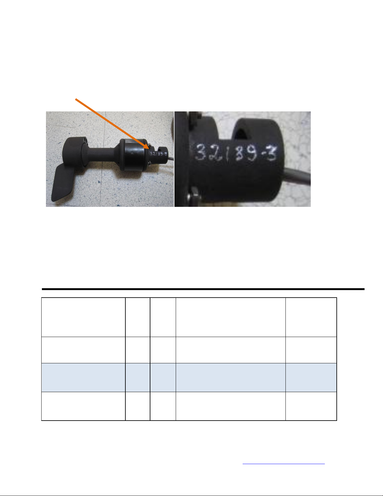
If the IceFree sensor has been calibrated, a sensor specific calibration report has been shipped with the sensor.
If the calibration report should get lost, you may contact NRG for a copy. Please note that you will need the
sensor serial number when you contact NRG.
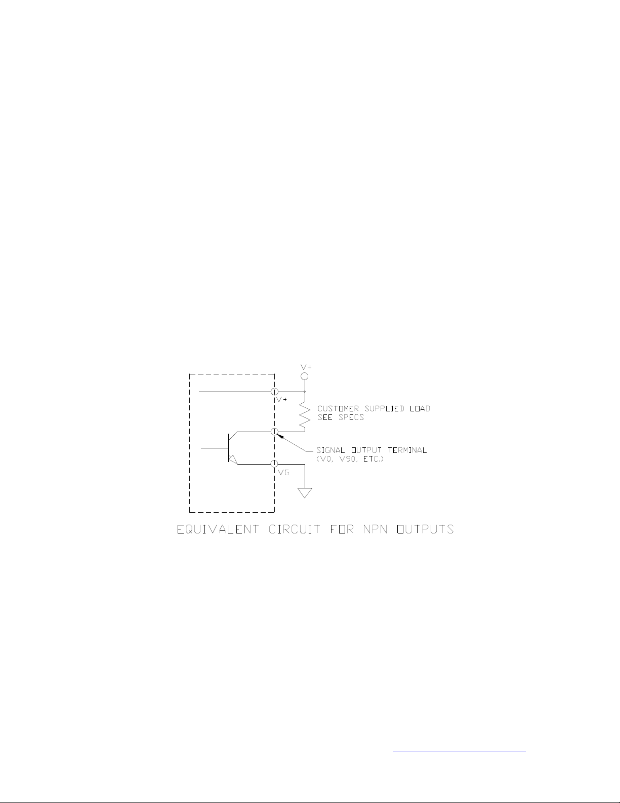
ESD, Circuit Protection, and Cautions
Do not apply greater than 30 Volts to the outputs at any time.
We suggest that you not mount the sensor until the proper grounding is available. When you mount the
sensor, protect the signal wires and connect the ground first. After connecting to ground, attach the
signal wires from the sensor.
There are internal TVS diodes on the output. If the output voltage is pulled above 30 V, or below ground,
the diode will clamp the output to ground.
Do not apply constant reverse voltages to the outputs. The internal diode is intended only to protect the
sensor output from transient reverse voltages, for example, the inductive turn-off spike caused by driving
reed-relay coils directly from the output.

IceFree3_Turbine_Control_Vane_Manual | Rev 3.0 | 30 January 2015 | [email protected] || 8
Sensor Maintenance
The bearings used in the IceFree3 sensors will last a minimum of 2 years. Sensor bearing life is variable and
depends upon the amount of exposure to salinity, dust, moisture, icing, vibration, and other environmental
factors. These factors independently, or in combination with each other, may reduce the bearing life. Routine
maintenance should be considered at 2 year intervals.

IceFree3_Turbine_Control_Vane_Manual | Rev 3.0 | 30 January 2015 | [email protected] || 9
NRG IceFree3™ Yaw Vane
4 Ch, NPN
Kit# 2451, 4107, 2652, 3292, 3450, 2850
FG# 2443, 4102, 2650, 3291, 3448, 2848
NPN Output Circuit Operation
The IceFree3™ yaw vane has four output signals, each centered on one of the four cardinal directions. The
outputs are open-collector type; they sink current to signal ground when active and are high impedance when
inactive.
Typically, these outputs are used with a pull up resistor from the output to the desired power supply, and then the
output is connected to a digital input on the controller. The active outputs are pulled low by the sensor, and when
the output is inactive, the signal is pulled high by the resistor to the supply voltage. This open-collector
arrangement allows you to choose the signal high voltage independently of the power input supply. The outputs
can also directly drive current loop inputs such as reed-relay coils or opto-isolated inputs, if the approximately 4
mA output drive capability is sufficient.
The opto-interrupters require an external power supply to operate the LED lamps. The sensor signals are
powered through an additional two wires: the red (excitation) and black (ground) wires.

IceFree3_Turbine_Control_Vane_Manual | Rev 3.0 | 30 January 2015 | [email protected] || 10
Interpreting Output Signals –4 Channels
The diagrams and table below indicate when each of the four outputs is active (1) or inactive (0) for each relative
direction the nose is pointing. For example, if the vane nose is pointing 55 degrees relative to the base, the VR
output (blue wire) and VR90 output (orange wire) will become active.
Output Signals
Azimuth Range
(clockwise
degrees)
VR
VL
VR90
VL90
5 to 175
1
0
0
0
185 to 355
0
1
0
0
95 to 265
0
0
0
1
275 to 85
0
0
1
0
Output Signal
Wire Color
VR
Blue
VL
Green
VL90
White
VR90
Orange

IceFree3_Turbine_Control_Vane_Manual | Rev 3.0 | 30 January 2015 | [email protected] || 11
[ Kit# 2451, 4107, 2652, 3450, 2850 ]
[ FG# 2443, 4102, 2650, 3448, 2848 ]
Sensor and Mounting Outline

IceFree3_Turbine_Control_Vane_Manual | Rev 3.0 | 30 January 2015 | [email protected] || 12
[ Kit# 3292, FG#3291 ] M8 Sensor and Mounting Outline

IceFree3_Turbine_Control_Vane_Manual | Rev 3.0 | 30 January 2015 | [email protected] || 13
[ Kit# 2451, 4107, 2652, 3292, 3450, 2850 ]
[ FG# 2443, 4102, 2650, 3291, 3448, 2848 ]
Specifications
Description
Sensor type
heated yaw error vane
Applications
wind turbine yaw control
Sensor range
mechanical range 360°
Output signal
Signal type
four NPN outputs, open-collector, active outputs sink current
can sink 4.0 mA at approximately 0.75 V drop; can sink 1.8 mA
at approximately 0.4 V drop
Transfer function
4 outputs, switch 5 degrees each side of relative north, south,
east, and west
Accuracy
+/- 3 deg
Power requirements
Supply voltage
8 V to 24 V DC
Supply current
30 mA typical; sensor power draw is internally regulated
Heater supply voltage
24 V AC/DC
optional transformer available
Heater supply current
Inrush: 8 A maximum
Steady state: 1 A at 20 °C (68 °F), 4 A under maximum thermal
load (head frozen in clear ice then powered on)
Response
characteristics
Threshold
<2 m/s
Installation
Mounting
mounts to a 27 mm (1.05 inch) diameter (3/4 inch IPS) pipe with a
5/16 inch nut and bolt(*FG#3291 uses M8 bolt); cabling exits into
mounting pipe
Tools required
13 mm (0.5 inch) nut driver
Environmental
Operating temperature
range
-40 °C to 60 °C (-40 °F to 140 °F)
Operating humidity
range
0 to 100% RH
Physical
Connections
Sensor Cable
red: power
black: ground
blue: VR
green: VL
orange: VR90
white: VL90
Heater Cable
black/white: heater power (AC/DC)
Cable length
Signal and power cables: See Quick ID Table
Weight
1.23 kg (2.7 pounds) not including cable
Dimensions
overall assembly height: 239 mm (9.41 inches)
body diameter: 70 mm (2.75 inches)
swept diameter: 212 mm (8.38 inches)
center to tail radius: 106 mm (4.19 inches)
Materials
Body
cast aluminum with black anodized finish and heat-resistant black
paint

IceFree3_Turbine_Control_Vane_Manual | Rev 3.0 | 30 January 2015 | [email protected] || 14
Shaft
centerless ground, stainless steel
Bearing
upper: sealed, stainless steel, ball bearing with application
specific lubrication
lower: modified teflon bearing
Wing
precision balanced aluminum with black anodized finish and heat-
resistant black paint
Cable
Signal: 6 conductor 22 AWG, Teflon jacket with braid shield and
drain, 3.6 m (12 feet) long
Heater: 2 conductor 20 AWG, Teflon jacket with braid shield
and drain
Enclosure
sealed to IP55
heater is epoxy encapsulated to IP65
sensor electronics epoxy encapsulated to IP65
Signal generator
epoxy encapsulated inside glass reinforced thermoplastic shell
Heater
fully encapsulated, self-regulating
Base
cast aluminum with black anodized finish and heat-resistant black
paint

IceFree3_Turbine_Control_Vane_Manual | Rev 3.0 | 30 January 2015 | [email protected] || 15
NRG IceFree3™ Yaw Vane
1 Ch, PNP
Kit# 2808, 3059
FG# 2807, 3057
PNP Output Circuit Operation
The IceFree3™ Yaw Error sensor has one output signal. The output is “PNP”, which means an active output
sources current from the sensor supply to the load on the output.
Typically, the output is used by connecting the output to a grounded load such as a relay or optical isolator in the
turbine controller. The active output powers the relay coil or opto-isolator loop, and when the output is inactive,
the load is off.
The opto-interrupters require an external power supply to operate the LED lamps. The sensor signals are
powered through an additional two wires: the red (excitation) and black (ground) wires.

IceFree3_Turbine_Control_Vane_Manual | Rev 3.0 | 30 January 2015 | [email protected] || 16
Interpreting Output Signals –1 Channel
The diagrams and table below indicate when the output is active (1) or inactive (0), for each relative direction the
nose is pointing. For example, if the vane nose is pointing 205 degrees relative to the base, the VR output (blue
wire) will become active.
Output Signal
Azimuth Range
(clockwise
degrees)
VR
190 to 360
1
Output Signal
Wire Color
VR
Blue

IceFree3_Turbine_Control_Vane_Manual | Rev 3.0 | 30 January 2015 | [email protected] || 17
[Kit# 2808, 3059]
[FG# 2807, 3057]
Sensor and Mounting Outline

IceFree3_Turbine_Control_Vane_Manual | Rev 3.0 | 30 January 2015 | [email protected] || 18
[Kit# 2808, 3059]
[FG# 2807, 3057] Specifications
Description
Sensor type
heated yaw error vane
Applications
wind turbine yaw control
Sensor range
mechanical range 360°
Output signal
Signal type
one PNP output, active output sources current from the sensor
power supply
can source up to 25 mA to within 1 V of the supply voltage
inactive output leakage is less than 100 uA
Transfer function
output switches 5 degrees each side of relative north
Accuracy
+/- 3 deg
Power requirements
Supply voltage
8 VDC to 24 VDC
Supply current
30 mA typical; sensor power draw is internally regulated
Heater supply voltage
24 V AC/DC
optional transformer available
Heater supply current
Inrush: 8 A maximum
Steady state: 1 A at 20 °C (68 °F), 4 A under maximum thermal
load (head frozen in clear ice then powered on)
Response
characteristics
Threshold
<2 m/s
Installation
Mounting
mounts to a 27 mm (1.05 inch) diameter (3/4 inch IPS) pipe with a
5/16 inch nut and bolt; cabling exits into mounting pipe
Tools required
13 mm (0.5 inch) nut driver
Environmental
Operating temperature
range
-40 °C to 60 °C (-40 °F to 140 °F)
Operating humidity
range
0 to 100% RH
Physical
Connections
Sensor Cable
red: power
black: ground
blue: VR
Heater Cable
black/white: heater power (AC/DC)
Cable length
Signal and heater cables: See Quick ID Table
Weight
1.23 kg (2.7 pounds) not including cable
Dimensions
overall assembly height: 239 mm (9.41 inches)
body diameter: 70 mm (2.75 inches)
swept diameter: 212 mm (8.38 inches)
center to tail radius: 106 mm (4.19 inches)
Materials
Body
cast aluminum with black anodized finish and heat-resistant black
paint
Shaft
centerless ground, stainless steel

IceFree3_Turbine_Control_Vane_Manual | Rev 3.0 | 30 January 2015 | [email protected] || 19
Bearing
upper: sealed, stainless steel, ball bearing with application
specific lubrication
lower: modified teflon bearing
Wing
precision balanced aluminum with black anodized finish and heat-
resistant black paint
Cable
Signal: 3 conductor 22 AWG, Teflon jacket with braid shield and
drain,
Heater: 2 conductor 20 AWG, Teflon jacket with braid shield
and drain
Enclosure
sealed to IP55
heater is epoxy encapsulated to IP65
sensor electronics epoxy encapsulated to IP65
Signal generator
epoxy encapsulated inside glass reinforced thermoplastic shell
Heater
fully encapsulated, self-regulating
Base
cast aluminum with black anodized finish and heat-resistant black
paint
Other manuals for IceFree3
1
Table of contents
Other NRG Systems Accessories manuals