Handling and Mounting Precaution
取り扱いと取り付け注意事項
2
軸取り付け
3Shaft mounting
カップリング
Coupling device
直結
Direct link
直結
Direct link
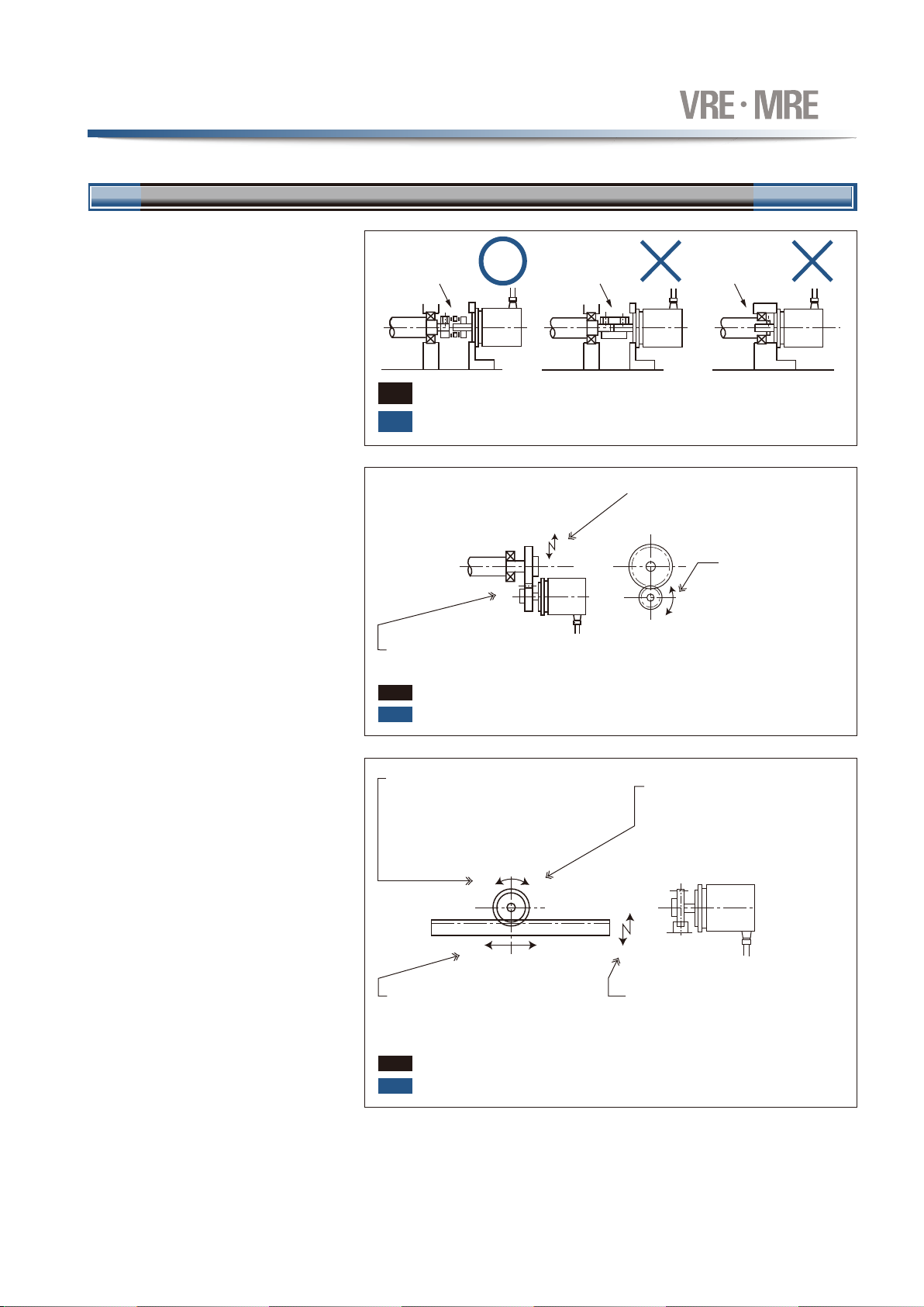
軸直結の場合、長時間の使用により軸が疲労し破損する場合がありますので、必ずカップリングを使用してください。
(推奨カップリングは[13-5]ページに示します)
A "direct-link" format will result in shaft fatigue and / or breakage after a long periods. Therefore, be
sure to use a coupling device to link the shafts. (Refer to page [13-5].)
振動・衝撃などによりギヤが振れたり、軸間距離が変化
しないようにしてください。
Be sure that the distance between shafts will not
be altered by vibrations shocks, etc.,
ギヤのどの回転位置でもバック
ラッシがあるように取り付けてく
ださい。
Be sure that backlash exists
at all gear positions.
ラックのどの位置でも、バックラッシがあるように
取り付けてください。
Be sure that backlash exists at all rack
positions.
振動、衝撃などにより、ラックとピニオンの軸間距離が
変化しないようにしてください。
Be sure that the distance between the rack and
pinion will not be altered by vibrations, shocks,
etc.
ラックは水平に移動し、ピニオン間距離が変化しない
ようにしてください。
Be sure that the distance between the rack
and pinion is not altered when horizontal
motion of the rack occurs.
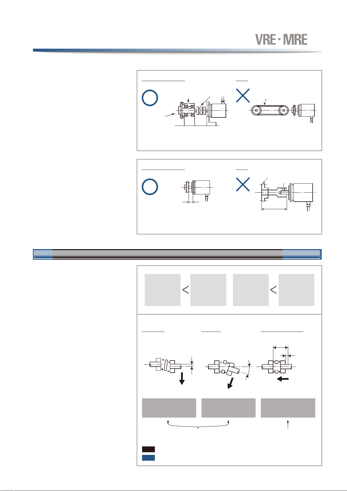
検出器軸ピニオンは、なるべく軽く(小さく)してください。振動・衝撃の多いところでは、特に注意してください。
The sensor shaft pinion should be as light (small) as possible. This is especially true for environments
where vibration / shock are likely.
検出器軸ピニオンは、なるべく軽く(小さく)してください。
振動・衝撃の多いところでは、特に注意してください。
The sensor shaft pinion should be as light (small)
as possible. This is especially true for environments
where vibration / shock are likely.
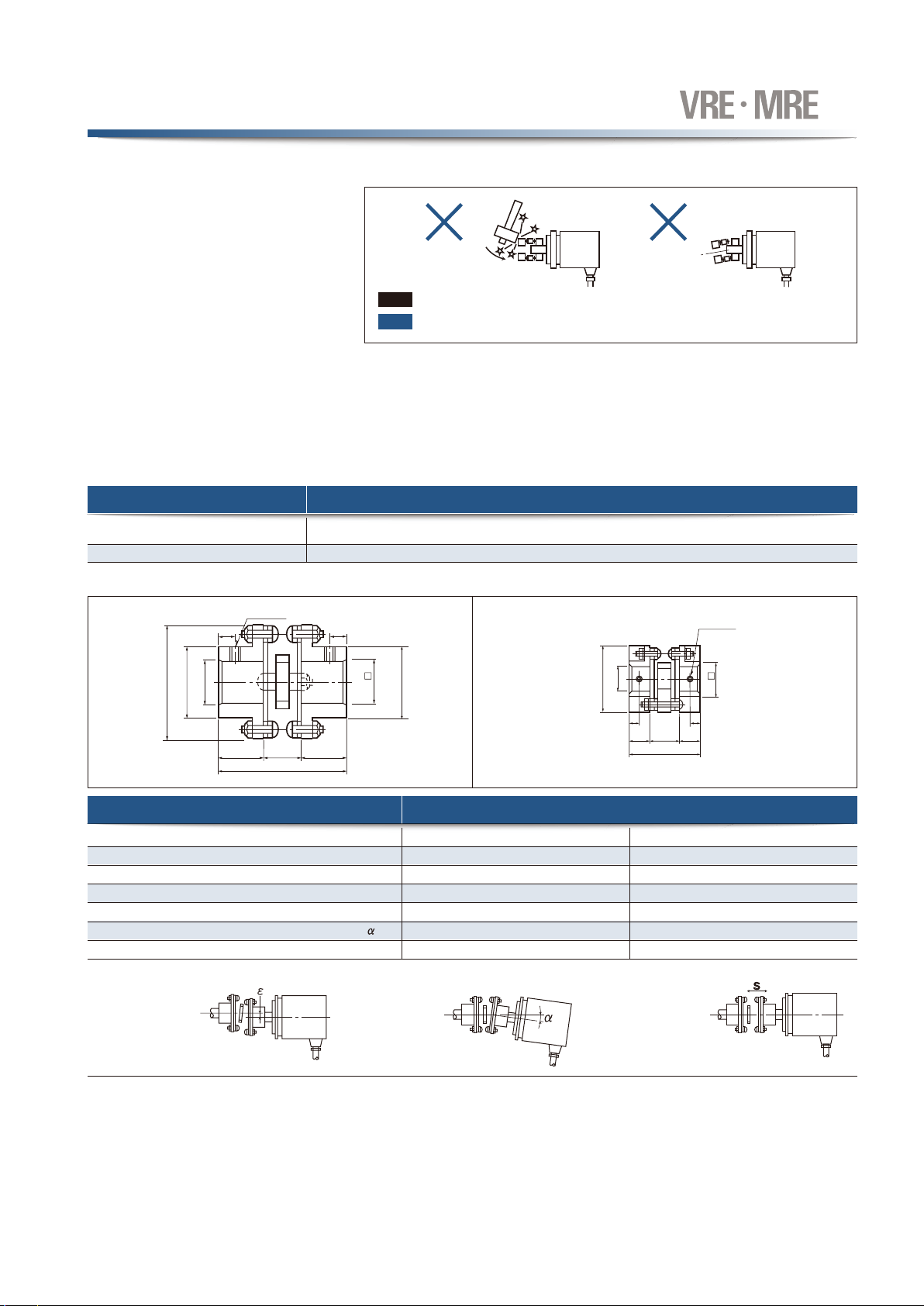
1)機械軸と検出器軸の結合
軸同士の場合は、必ずカップリングを使用して
ください。
Be sure to use a coupling device to link the 2
shafts.
Coupling of machine shaft and sensor shaft
2)ギヤ結合
ギヤ結合の場合には、必ずバックラッシがある
ようにしてください。
If a gear linkage is used, be sure that some
backlash exists.
For gear-type linkage
3)ラックピニオン
ラックのどの位置でも、必ずバックラッシがある
ようにしてください。
Be
sure
that
backlash
exists
at
all
rack
positions.
For rack and pinion type linkage
注意
Note
取り付け状態が悪い場合、軸が曲がったり破損する場合がありますので、注意してください。
Incorrect gear mounting can result in shaft bending or breakage.
注意
Note
取り付け状態が悪い場合、軸が曲がったり破損する場合がありますので、注意してください。
Incorrect rack and pinion mounting can result in shaft bending or breakage.
注意
Note