NSE UC-100 Plus User manual

HD Endoscope Video System
User Manual, Version A/1
Model: UC-100 Plus

Read Before Use
Thank you for purchasing this product from Guangzhou North-Southern Electronics!
This manual is intended to introduce this product’s safety information, technical
parameters, operational method, and maintenance instructions. Please be kindly
reminded to read this manual carefully to properly use this product. To achieve the
optimum performance of the product, please follow the operational and mainte-
nance methods specified in this manual.
Special attention shall be paid to the following:
•Keep this manual in places that are easy to reach make it easier to refer to.
•Keep this manual properly when not in use to avoid loss and damage.
Warning signs below are defined to ensure safe and proper operation.
Warning: Such kind of information cannot be ignored, or it may lead to potential
safety hazards or product damage.
Attention: This is to remind readers that the important message following the
sign shall be learned, though it may not be necessarily related to possible per-
sonal injury or product damage.
Guangzhou North-Southern Electronics reserves all the rights of final explanation.

Parts for Inspection
All the mentioned parts shall be examined to see if they are complete and intact
once the packaging case is opened. Please contact your supplier immediately if
there’s any missing or broken part.
1 Main recording unit x1
2 Camera handle x1
3 Optical mount (Supported specifications: 2/25/28/32/35mm) x1
4 Light source (Optional: portable LED light source/ LED light source) x1
5 SD card x1
6 HDMI cable x1
7 AC line x1
8 Certification x1
9 User manual x1

CONTENTS
01 1 Overview
01 1.1 Product Name
01 1.2 Model and Specification
01 1.3 Structural Composition
01 1.4 Scope of Application
01 1.5 Contraindications
02 1.6 Introduction to the Figures, Symbols, and Abbreviations in the Labels
02 1.7 Environmental Criteria
02
03 2 The Product’s Structure
03 2.1 Product Sketch Map
04 2.2 Buttons and Display Screen
04
05 3 Installation and Operation
05 3.1 Camera Handle Installation
06 3.2 Main recording unit and Light Source Installation (Optional)
07 3.3 SD Card Installation
08 3.4 Video Output Connection
08 3.5 System Startup
08 3.6 Light Source Brightness Adjustment
09 3.7 Focal Length Setting
09 3.8 Photo Taking/Video Recording Operation
10 3.9 System Setup
11 3.10 Introduction to the System Setup Functions

11 3.10.1 Light Source Setup
11 3.10.2 White Balance
12 3.10.3 Date Label
12 3.10.4 Formatting
13 3.10.5 Default Setting
13 3.10.6 Version
13
14 4 Product Maintenance
14
15 5 Common Trouble Shooting
15 5.1 Abnormal System Running Status
15 5.2 File Save Failure
15 5.3 Image Blurring
16 5.4 Black Block in Images
16
17 6 Technical Parameters

01
1 Overview
1.1 Product Name
1.2 Model and Specification
1.3 Structural Composition
1.4 Scope of Application
1.5 Contraindications
HD Endoscope Video system
UC-100 Plus
This product is composed of a main recording unit, a camera handle, a light source,
and an optical mount. The endoscope is connected to the optical mount of the
handle, while the handle is connected via a plug onto the port located on one side
of the main recording unit. The main recording unit is directly powered by the AC
mains supply. A 720P high definition display screen is installed at the front panel.
The light source brightness is directly adjusted by independent rotary knobs. The
video can be directly showed in the display screen via an HDMI cable. Moreover,
this main recording unit also has an SD card slot for video storage.
This product is to be connected to an optical endoscope and used for real-time
observation and recording of the endoscopy.
Currently no contraindication has been found.

02
1.6 Introduction to the Figures, Symbols, and Abbreviations in the
Labels
1.7 Environmental Criteria
Symbol Explanation
Attention! Please refer to the attached files.
Refer to the instructions.
This symbol indicates the need to respectively collect electrical and
electronic equipment in line with WEEE provisions.
The product is recyclable.
Environmental requirement Operational environment Storage and transportation
environment
Ambient Temperature 5°C ~ 40°C -10°C ~ 55°C
Relative Humidity 20% ~ 80% 10% ~ 95%, non-condensing
Atmospheric pressure 86 kPa ~ 106 kPa 86kPa ~ 106kPa

03
Figure 1 Product Diagram
2 The Product’s Structure
2.1 Product Sketch Map
SD card slot
Capture button
Camera handle jack
Display screen
Power Switch
Recording button
AC power input port
HDMI output

04
2.2 Buttons and Display Screen
The main recording unit is composed of 3 control buttons and one 4.5 inches
display screen for control operation and status indication. Its function is as shown
in Table 1.
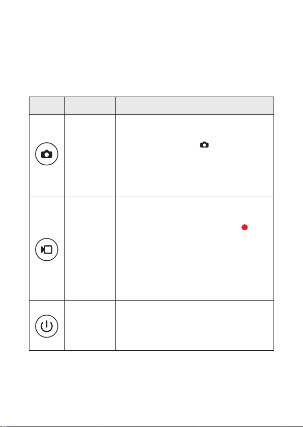
Icon Name Function Description
Capture button
•Short press this button to activate the camera function;
•Short press this button until a “beep” sound is heard,
the button lights up, and the icon can be seen at the
top right corner of the display screen. At this time, the
memory card will start saving the picture. Aer that,
it will automatically exit the camera function, and the
light will be o.
Recording
button
•Short press the button to start or stop video recording.
•Short press this button until a “beep” can be heard, the
button lights up and flashes, and the red dot icon is
displayed at the top right corner of the display screen.
At this time, the memory card will start saving the video
file. Aer you short press the button until it beeps again,
the storage will be completed and the video recording
function will be exited. Then, the light of the recording
button will be o.
Power switch
•Short-pressing the button until it beeps will turn on the
power and the light of the power supply button.
•Long-pressing the button until it beeps will turn o the
power and the light of the power supply button.
Table 1 Buttons

05
3 Installation and Operation
3.1 Camera Handle Installation
Before use, the camera handle and light source shall be installed first. The follow-
ing are its detailed steps:
(1) Rotate and tighten the optical mount to the handle.
(2) Squeeze the switch of the optical mount, and install the endoscope to the
mount. Then loosen the switch, and the endoscope will be automatically fastened.
(3) Install the light source optical fiber or an end of portable LCD light source with
nuts in the light input port of the endoscope. Then fasten the nut.
(4) Aer the front end of the handle is installed, insert its plug into the handle jack
on one side of the main recording unit. Also, insert the optical fiber or the other
side of the portable light source in the light output jack. Then the whole process is
completed.
Install the light source LED light output jack
Endoscope Optical Camera handle
Figure 2 Camera Handle Installation
Attention: The endoscope is fragile to impact, so please pay close attention to
the lens during installation.

06
3.2 Main recording unit and Light Source Installation (Optional)
(1) Option 1: Portable LED light source
I. Insert one end of the LED light source plug of the endoscope into the 2Pin
light source socket at the end of the camera handle. Install the other thread-
ed end into the light input port, and the endoscope is now usable.
II. Insert the 2Pin plug of LED light source line of the endoscope to the LED
light source output jack of the camera handle. Please match the red dots in
the LED light source line of the endoscope with red dots in the light source
output jack correspondingly.
(2) Option 2: If the LED light source is selected, the main recording unit and light
source base shall be installed. Spring contacts are used to connect the light source
base and main recording unit. The light source base shall be connected to a power
supply (as shown in Figure 3). Here are the detailed steps:
I. Align the convex groove at the bottom of the main recording unit to that at
the top of the light source base. Gently push it into the bottom to make it
clamp (push it out of the card slot to separate them)
II. Aer the main recording unit and light source base are installed, dismantle
the protective cap on the plug of the equipped optical fiber.
III.Insert the plug of the equipped optical fiber to the
IV.flashing socket of the light source base.
V. Install the other end of the threaded optical fiber to the light source port of
the endoscope; once this is done, it can be used.

07
3.3 SD Card Installation
Take out the SD card from the packing case, and insert it into the SD card slot in the
front panel of the main recording unit. Then the SD card installation is completed.
Attention:The main recording unit must be shut down before the SD card is in-
serted. If not, the main recording unit will be automatically turned o.
Attention:If this is the first time installing the SD card, please format the SD card
in “system setup” menu. Refer to Chapter 3.10.3 for specific operation methods.
Card Slot
Optical fiber socket
Figure 3 Light Source Installation

08
3.4 Video Output Connection
3.5 System Startup
3.6 Light Source Brightness Adjustment
Take out the HDMI cable from the packing case, then connect it to the HDMI output
port in the front panel of the main recording unit. The other end shall be connected
to the display screen at the HDMI input. Information shown in the external monitor
should be consistent with that in the main recording unit display screen.
Attention: Just one output video is available in one usage, i.e., only one of LCD
or HDMI.
Attention: current illuminating brightness settings will be saved automatically
before the system shutdown.
Install the camera handle and light source, connect the AC cables to both AC ports
on the side plate of the main recording unit, then short press the switch button
on the front panel of the main recording unit to initiate system startup. It will beep
aer about 3 to 5 seconds, then images will show in the camera.
The light source button in the upper part of the camera handle can be pressed
to control the brightness. There are 5 levels of brightness. Every time aer the
button is short-pressed, the brightness will be increased. When the brightness
reaches the maximum, short-pressing the button will turn o the light. The
current brightness level is shown at the top le corner of the display screen.

09
3.7 Focal Length Setting
Aer starting up, manually rotate the optical mount to adjust the focal length until
the clearest image appears in the display screen (as shown in figure 4).
Rotate here to adjust the focal length
Figure 4 Optical Mount- Focal Length Adjustment
3.8 Photo Taking/Video Recording Operation
Press the capturing / recording button on the front panel of the main record-
ing unit to take pictures or record a video (but a memory SD card must be inserted).
Here’s the operation method:
(1) Video recording
Aer the system startup, short press the recording button to record a video.
Then at the top right corner of the image shown in the display screen, a flashing
red round dot will appear, indicating the video recording session is ongoing. Short
press the recording button again to exit the session. Attention: in the video
recording mode, no other operation can be handled, including menu or picture
taking, etc., but light source brightness adjustment is allowed.

10
3.9 System Setup
Table 2 Functions of Main Interface of System Setup
(2) Picture taking
Aer the system startup, you can take pictures directly as needed just by
short-pressing .
Videos or pictures can be read by the built-in SD card. Pictures are stored in the
folder “DCIM-Photo” in .JPG format, while videos are stored in folder “DCIM-Movie”
in .MP4 format. The main recording unit system adopts “recording date + recording
start date (hour, minute and second) + Serial No.” to automatically name the folder.
The name shall be in the format of YYYY_MMDD_HHMMSS_XXX
Firstly, check the Main recording unit to make it not in illumination adjustment
mode. Then long press the capturing button to get the main interface of system
setup. The following operations can be conducted on the main interface (as shown
in table 2):
Attention: The system sets a fixed duration and the maximum storage size of
a single file. When the video duration of a single recording is less than a fixed
duration, the actual duration shall be stored; If the duration of a single video ex-
ceeds a fixed duration, the system will save it as multiple files according to the
fixed duration/segment.
Attention: Please check SD card capacity before use and timely backup the files
into your local hard disk.
Attention: Insert the SD card into the main recording unit first if the file size is
larger than 32G, then go to menu to format it. The SD card can only be used nor-
mally aer formatting and restarting.
1.Exposure compensation 2.Photometry 3.Storability
4.Light source setting 5.White balance 6.Language setting
7.Date label 8.LCD height adjustment 9.Media playback
10.Date/time 11.Formatting 12.Default settings
13.Version

11
3.10 Introduction to the System Setup Functions
3.10.1 Light Source Setup
3.10.2 White Balance
Aer entering the main interface of system setup, please operate according to table 3.
Light source setup works to adjust built-in white balance parameters. If a portable
LED light source is used, please set up it as 1. If a LED light source is used, please
set up it as 2.
In white balance setup, the white balance can be either turned on or o. When it’s
o, RGain and BGain can be set up to adjust the color of pictures.
(1) Long press the capturing button to enter the main interface of system setup
menu.
(2) Short press capturing button and video button to go up and down, select
“white balance” option, and then long press the capturing button for white
balance setup.
Table 3 System Setup: Buttons Operation
Move up Short press in system setup interface to move up settings.
Move down Short press in system setup interface to move down settings.
Enter settings Aer settings are selected, long press to enter secondary menu
to set values.
Save settings Aer making changes, long press to save changes and go back
to the previous menu.
Aer system setup is finished, long press to close the “system setup” main interface.

12
(3) Short press the capturing button and recording button to go up of down
to turn on or o AWB auto white balance. When turning o it, white balance can be
operated manually, and RGain parameter shall be rectified from 0 to 1,024. Long
press the capturing button to confirm setup selection.
(4) Aer setup, long press the recording button to go back to the previous menu.
3.10.3 Date Label
3.10.4 Formatting
The date label refers to the timestamp in the bottom right corner of previewed and
recorded video. It can be used to turn on or o the timestamp.
(1) Long press the capturing button to enter the main interface of system setup
menu.
(2) Short press the capturing button and the recording button to move up
and down, select “formatting” option, and long press for SD card formatting (as
shown in figure 5).
(3) Short press the capturing button and the recording button to move le
and right to select confirmation or cancellation. Long press the capturing button
to confirm your selection (as shown in figure 6).
(4) Aer operations above are completed, long press the recording button to go
back to the previous menu.
Figure 5 Sketch Map of Formatting Settings Figure 6 Sketch Map of Formatting
SD Card Interface
System setup
Media playback
Date/time
Formatting
Default setting
Formatting the memory card
will delete all the data
Cancel Confirm

13
3.10.5 Default Setting
(1) Long press the capturing button to enter the main interface of system setup
menu.
(2) Short press the capturing button and the recording button to move up
and down. Select “default setting”, and long press the capturing button to go
back to system default settings (as shown in figure 7).
(3) Short press the capturing button and the recording button to move right
and right to confirm or cancel system default settings. Long press the capturing
button to confirm your selection (as shown in figure 8).
(4) Aer operations above are completed, long press the recording button to go
back to previous menu.
3.10.6 Version
(1) Long press camera button to enter the main interface of system setup menu.
(2) Short press the capturing button and the recording button to move up
and down. Select “version”, and then long press to check and immediately find
current soware version (as shown in figure 9).
(3) Aer operations above are completed, long press the recording button to go
back to previous menu.
Figure 7 Sketch Map of Default settings Figure 8 Sketch Map of Resetting to
Factory Default Settings
System setup
Media playback
Date/time
Formatting
Default setting
Reset to default settings
Cancel Confirm

14
Figure 9 Sketch Map of Version Settings
System setup
Version
4 Product Maintenance
(1) The main recording unit shall be power o before cleaning.
(2) Wipe the external surface of the product gently with the so cloth and neutral
detergent. Do not drop the solution into the jack when wiping.
(3) Clean and dry all parts with the dry cloth.
Attention: This product does not apply to biocidal treatment. The sterilization
cover is recommended to be used for protection.
Warning: This is a sophisticated electronical equipment. Any dismantling will
lead to unrecoverable product damage and unavailability.

15
5 Common Trouble Shooting
5.1 Abnormal System Running Status
5.2 File Save Failure
5.3 Image Blurring
Problem description:
Pictures are not shown or moving in the display screen.
Cause analysis:
connection interruption between camera mount and the main recording unit,
or camera handle damage.
Solution:
Shut down the main recording unit, then pull out the connecting line of the
coaxial camera mount. Restart aer inserting the connecting line again, which
must be firmly connected.
Problem description:
The dialog “Please insert SD card” pops up in the display screen.
Cause analysis:
SD card is not inserted or damaged.
Solution:
Shut down the main recording unit. Restart aer the SD card is inserted. If
there’s any SD card damage, please replace with a new one to try again.
Problem description:
(1) The display screen just shows stripe images instead of round one.
(2) It can show round images, but they are blurring.
Cause analysis:
(1) The camera mount is not well connected;
(2) The main recording unit start-up is abnormal;
(3) The focal length of camera mount is not well adjusted.
Table of contents
Other NSE Medical Equipment manuals