manuals.online logo
Brands
  1. Home
  2. •
  3. Brands
  4. •
  5. Nibe
  6. •
  7. Boiler
  8. •
  9. Nibe VPA 300/200 User manual

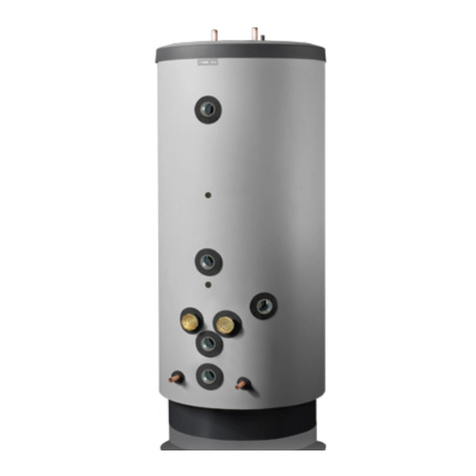
Nibe VPA 300/200 User manual

Other manuals for VPA 300/200

3

This manual suits for next models

1

Other Nibe Boiler manuals

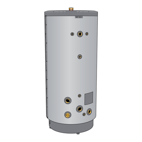
Nibe EKS 750 User manual

Nibe

Nibe EKS 750 User manual

Nibe PELLUX 100 User manual

Nibe

Nibe PELLUX 100 User manual

Nibe PELLUX 100 User manual

Nibe

Nibe PELLUX 100 User manual

Nibe PUB2 160 Use and care manual

Nibe

Nibe PUB2 160 Use and care manual

Nibe EVC 13 User manual

Nibe

Nibe EVC 13 User manual

Nibe VEDEX 3300 User manual

Nibe

Nibe VEDEX 3300 User manual

Nibe UKV 500 Use and care manual

Nibe

Nibe UKV 500 Use and care manual

Nibe VPA 300/200 User manual

Nibe

Nibe VPA 300/200 User manual

Nibe VPB 500 Use and care manual

Nibe

Nibe VPB 500 Use and care manual

Nibe NIBE VVM 300 User manual

Nibe

Nibe NIBE VVM 300 User manual

Nibe UKV 500 Use and care manual

Nibe

Nibe UKV 500 Use and care manual

Nibe VVM 225 User manual

Nibe

Nibe VVM 225 User manual

Nibe HK 15 Use and care manual

Nibe

Nibe HK 15 Use and care manual

Nibe EKS 500 NL Use and care manual

Nibe

Nibe EKS 500 NL Use and care manual

Nibe Eminent Series Use and care manual

Nibe

Nibe Eminent Series Use and care manual

Nibe NIBE GBM 10-15 Operation and installation manual
Nibe

Nibe NIBE GBM 10-15 Operation and installation manual

Nibe VEDEX 3300 User manual

Nibe

Nibe VEDEX 3300 User manual

Nibe EVC 13 User manual

Nibe

Nibe EVC 13 User manual

Nibe VPB Use and care manual

Nibe

Nibe VPB Use and care manual

Nibe AHPS User guide

Nibe

Nibe AHPS User guide

Nibe VVM 320 User guide

Nibe

Nibe VVM 320 User guide

Nibe EKS 750 User manual

Nibe

Nibe EKS 750 User manual
Nibe VVM 310 Original operating manual

Nibe

Nibe VVM 310 Original operating manual

Nibe ELK 42 User manual

Nibe

Nibe ELK 42 User manual

Popular Boiler manuals by other brands

IDEAL IMAX XTRA EL 320 user guide

IDEAL

IDEAL IMAX XTRA EL 320 user guide

UTICA BOILERS BC3D Installation, operation & maintenance manual

UTICA BOILERS

UTICA BOILERS BC3D Installation, operation & maintenance manual

Lochinvar SOLUTION 260000 Installation & service manual

Lochinvar

Lochinvar SOLUTION 260000 Installation & service manual

Weil-McLain EG 6 Series manual

Weil-McLain

Weil-McLain EG 6 Series manual

RBI LCD Series Installation & operation manual

RBI

RBI LCD Series Installation & operation manual

Baxi MainEco Combi 28 Installation and service manual

Baxi

Baxi MainEco Combi 28 Installation and service manual

Unical ALKON R 24 Installation and Servicing Manual

Unical

Unical ALKON R 24 Installation and Servicing Manual

Automatic Heating Gasogen Installation and Servicing Manual

Automatic Heating

Automatic Heating Gasogen Installation and Servicing Manual

Viessmann VITORADIAL 300-T Type VR3 Service instructions for contractors

Viessmann

Viessmann VITORADIAL 300-T Type VR3 Service instructions for contractors

Alpha GasSaver GS-1 Installation and servicing instructions

Alpha

Alpha GasSaver GS-1 Installation and servicing instructions

Baxi ROCA LAURA PLUS 28/28 Operating, cleaning and maintenance instructions for the user

Baxi

Baxi ROCA LAURA PLUS 28/28 Operating, cleaning and maintenance instructions for the user

Vaillant uniSTOR VIH SW GB 500 BES operating instructions

Vaillant

Vaillant uniSTOR VIH SW GB 500 BES operating instructions

Kärcher HWE 4000 Gas manual

Kärcher

Kärcher HWE 4000 Gas manual

Radijator BIO max 23.1 instruction manual

Radijator

Radijator BIO max 23.1 instruction manual

Granby BKC Installation, operation and maintenance manual

Granby

Granby BKC Installation, operation and maintenance manual

Brunner BSV 20 Instructions for use

Brunner

Brunner BSV 20 Instructions for use

Potterton 50e Installation and Servicing Manual

Potterton

Potterton 50e Installation and Servicing Manual

UTICA BOILERS TriFire Assembly instructions

UTICA BOILERS

UTICA BOILERS TriFire Assembly instructions

manuals.online logo
manuals.online logoBrands
  • About & Mission
  • Contact us
  • Privacy Policy
  • Terms and Conditions

Copyright 2025 Manuals.Online. All Rights Reserved.

MOS UK 1333-9
VPA 300/200, 450/300
031049
INSTALLATION AND MAINTENANCE INSTRUCTIONS
VPA 300/200, 450/300
LEK
3VPA 300/200, 450/300
For Home Owners
Benchmark places responsibilities on both manufacturers and installers. The purpose is to ensure that customers are provided with the correct
equipment for their needs, that it is installed, commissioned and serviced in accordance with the manufacturers instructions by competent persons
and that it meets the requirements of the appropriate Building Regulations. The Benchmark Checklist can be used to demonstrate compliance with
Building Regulations and should be provided to the customer for future reference.
Installers are required to carry out the installation, commissioning and servicing work in accordance with the Benchmark Code of Practice which is
available from the Heating and Hotwater Industry Council who manage and promote the Scheme.Visit www.centralheating.co.uk for more informa-
tion.
System description
System description
Unvented water heater for use with ground source heat
pump / air source heat pump units for central heating and
tap water production.
CP
HR
FG
RGBV
SMO 10
UG
BVAV
CPRV SF
TV
SÄV
SÄV
VXV
VVG
VPA
VP HR
SÄV
AV BV AV
EXP
Tillsatsvärme
Additional heat
T&P
Note! This is an outline diagram. Actual installations must be planned according to applicable standards.
Components
AV Shut-off valve
BV Non-return valve
CP Circulation pump
EXP Expansion vessel
FG Flow line sensor
HR Auxiliary relay
RG Return line sensor
RV Control valve
SF Particle filter
SÄV Safety valve
T&P T&P-valve
TV Drain valve
UG Outdoor sensor
VP Heat pump
VVG Hot water sensor
VXV Reversing valve
Additional heat
4VPA 300/200, 450/300
For Home Owners
Maintenance routines/ Dealing with malfunctions
Maintenance
General inspection
Check the following:
1. Condition of casing.
2. Electrical connections.
3. Pipe connections.
Correct any fault before continuing.
Hot water heater
Check the following:
1. Expansion relief valve.
2. T&P valve.
3. Discharge pipe.
4. Expansion vessel.
Correct any fault before continuing.
Do not remove or adjust any component part
of this unvented water heater: Contact the
installer.
Warning to the user!
If this unvented water heater develops a
fault, such as a flow of hot water from the
discharge pipe, switch the heater off and
contact the installer.
Warning to the user!
After servicing, complete the relevant Service
Interval Record section of the Benchmark
Checklist located at the back of this docu-
ment. Completion of the Service Interval
Record is a condition of warranty. For full
terms and conditions of warranty, please see
our website www.nibe.co.uk.
Note!
Any servicing must be carried out by a
competent person.
Note!
Service actions
Safety valves
The function of the safety valves must be checked regu-
larly. Perform checks as follows:
1. Open the valve by turning the knob anti-clockwise
carefully.
2. Check that water flows through the valve.
3. Close the valve by releasing it. If it does not close auto-
matically when released, turn it anti-clockwise slightly.
Do not remove or adjust any components
that are part of this pressurised water heater.
Contact your installer!
Note!
5VPA 300/200, 450/300
For the Installer
Warning to the installer!
This installation is subject to building regulation
approval, notify the local Authority of intention
to install.
Warning to the installer!
Use only manufacturer’s recommended replace-
ment parts.
General information for the installer
General
The water heater is unscrewed from the pallet and lifted
into position, use the lifting eye on the top if necessary.
Mount the enclosed cover discs before pipe installation.
The cover discs, which have s adhesive backing, should be
mounted at each connection by pressing them over the
connections. All connections (including connections that
are not used) should be isolated to minimize idling losses.
The water heater may only be installed vertically and can
be aligned using the adjustable feet (10).
Once the water heater is in the correct position, remove
the lifting device from the top.
Fit the enclosed insulation plug in the hole left by the
lifting eye (40).
If a secondary return circuit is used, an additional expen-
sion vessel can be required.
Assembly
• The water heater is only designed for upright installa-
tion.
• Position the water heater on a firm base that can bear
• its weight, preferably on a concrete floor or founda-
tion. Use the water heater’s adjustable feet to obtain a
horizontal and stable set-up.
• The water heater’s installation area should always have
a temperature of at least 10 °C (to prevent the risk of
damage from frost) and max 30 °C.
General information for the installer
Please ensure that the manual is left with the
householder when installation is complete.
Note to the installer!
VPA 300/200 VPA 450/300
Tryckfall
Flöde
0,0
0,5
1,0
1,5
2,0
2,5
(kPa)
0 0,2 0,4 0,6 0,8 1,0 l/s
Pressure
drop
(kPa)
Flow
(l/s)
0,0
0,5
1,0
1,5
2,0
2,5
3,0
(kPa)
0,0 0,1 0,2 0,3 0,4 0,5 0,6 l/s
Flöde
Tryckfall
Pressure
drop
(kPa)
Flow
(l/s)
6VPA 300/200, 450/300
For the Installer
Pipe connections
General
Pipe installation must be carried out in accordance with
current norms and directives.
Internal support bushes should be fitted when a plastic
pipe or annealed copper pipe is used. The water heater
must be fitted with the requisite valves, such as a safety
valve, shut-off valve, non-return valve, and vacuum valve.
An overflow pipe must be routed from the safety valve to
a suitable drain. The size of the overflow pipe must be the
same as on the safety valve. Route the overflow pipe from
the safety valve enclosed along its entire length and ensure
that it is frost proof. The outlet of the overflow pipe should
be visible and clearly away from any electrical components.
Overflow water from the safety valves goes via nonpressu-
rised collecting pipes to a drain so that hot water splashes
cannot cause injury. These non-pressurised collecting pipes
shall not be used for anything else. A discharge pipe from
the tundish connected to the expansion relief valve (safety
valve) shall also be connected to a drain in the same way.
Please note that the connection of the T&P-valve should
not be used for any other purpose.
Valves may not be positioned between the expansion valve
and the vessel.
Discharge pipes from tundishes shall have av vertical sec-
tion of pipe at least 300 mm long, before any elbows or
bends in the pipework (see following picture).
600 mm maximum
Matal discharge pipe from tundish,
with continous fall.
300 mm
minimum
Tundish
Safety device
(e.g. temperature
relief valve)
Metal discharge pipe from
temperature relief valve to tundish
Possible wall
Discharge below
fixed grating
Fixed grating
Trapped gulley
Valve outlet size Minimum size of
discharge pipe
Minimum size of
discharge pipe from
tundish
Maximum resistance
allowed, expres-
sed as a length of
straight pipe (i.e. no
elbows or bends)
Resistance created
by each elbow or
bend
G1 / 2 15 mm 22 mm up to 9 m 0,8 m
G1 / 2 15 mm 28 mm up to 18 m 1,0 m
G1 / 2 15 mm 35 mm up to 27 m 1,4 m
G3 / 4 22 mm 28 mm up to 9 m 1,0 m
G3 / 4 22 mm 35 mm up to 18 m 1,4 m
G3 / 4 22 mm 42 mm up to 27 m 1,7 m
G1 28 mm 35 mm up to 9 m 1,4 m
G1 28 mm 42 mm up to 18 m 1,7 m
G1 28 mm 54 mm up to 27 m 2,3 m
Pipe connections
NOTE!
The expansion vessel accomodates expansion that
results from heating the water inside the unit. The
expansion vessel must be connected between the
expansion valve and the cylinder.
The location of the expansion vessel should allow
access to recharge the pressure as and when
necessary.
Hard water areas
Usually, there should not be a problem in installing VPB/
VPBS in areas of hard water as the operating temperature
is 50-60 °C.
Cleaning the system
When the water heater and the climate system have been
filled with water, VPA must operate at maximum normal
temperature for at least one hour. Thereafter the system
must be drained of water and refilled.
7VPA 300/200, 450/300
For the Installer
External heat source
(maximum 25 kW)
161
3
145
162
106
148 165
Principle scheme
Symbol key
3 Pocket tube
106 Expansion vessel
145 T&P-valve
148 Pressure reduction valve
161 Temperature limiter
162 Shut off valve
165 Cold water inlet and pressure relief valve, water
heater
Pipe connections
There´s a plug on the cold water inlet valve that can be
removed and there mount the flexible hose for the ex-
panssion vessel.
The water heater is equipped with one outgoing dock-
ing connection (5).
A drain valve can be fitted to the G11/2” or G2” con-
nection (5) (use an adapter from G11/2” or G2” to the
required size) which is not used for docking.
8VPA 300/200, 450/300
For the Installer
Electrical connections
Immersion heaters
VPA can be supplemented with one or two immersion hea-
ters. The connection size is G2” and the maximum immer-
sion heater length is 650 mm.
Connect the temperature limiter (161) and the shut off
valve (162) with 230V.
Electrical installation and service must be
carried out under the supervision of a
qualified electrician. Electrical installation
and wiring must be carried out in accor-
dance with the stipulations in force.
NOTE!
Sensors
VPA can be supplemented with one hot water sensor, for
display and control. The sensor is positioned in the pocket
tube for the sensor (8).
Use the sensors provided with the heat pump/control
module. When no heat sensors have been provided these
must be ordered from the manufacturer of the heat pump/
control module.
Electrical installation
Temperature limiter
Power supply to temperature limiter (161) is 230 V.
Connect temperature limiter electrically to the solenoid
valve for the heat source.
L
E
K
Temp. limiter
Terminal block
Cable from
solenoid valve
Supply cable
230 V
9VPA 300/200, 450/300
For the Installer
Filling the water heater
The water heater is filled by first opening a hot water tap
in the system and then opening the cut-off valve on the
incoming cold water. This valve should then be fully open
during operations. When only water comes out of the hot
water tap (initially an air-water mixture comes out of the
tap) can the tap be shut off and the water heater is filled.
Filling the heating system
QConnect the nessesary valves to the system between
the incoming cold water pipe and the heating system.
Open the filling valve. The primary part of the VPA can
now be filled with water.
QAfter a while the pressure gauge, if installed, will show
rising pressure. When the pressure reaches the set pres-
sure a mixture of air and water starts to emerge from
the pessure relief valve (not supplied). The filling valves
are then closed.
QTurn the pessure relief valve until the boiler pressure
reaches the normal working range (0.5 - 1.5 bar).
When filling the heating system, the double-jacketed space
should be vented by opening the air nipple (6) (300/200).
The air nipple can be closed when water comes out of the
air hole.
QVent the heating system through the pessure relief
valve and the air nipple (6) (300/200). The remainder of
the heating system is vented by means of each venting
valve.
QKeep topping up and venting until all air has been re-
moved and the pressure is correct.
NOTE!
When filling up the system you have to fill up the
waterheater first then the heating system.
Commissioning and adjusting
10 VPA 300/200, 450/300
For the Installer
Service
Emptying water heater
Emptying the water heater takes place through the siphon
in the cold water connection (1). The hot water tap in the
system can be opened and a pipe coupling on the hot wa-
ter side can be loosened to provide an air supply.
Emptying heating system
Empty the double jacketed space through the siphon on
the docking connection (5), outgoing to the external heat
source.Here the air nipple (6) can be openedto supply air.
The entire heating system must be taken into consideration
before emptying the double-jacketed space.
Cleaning
Inspect and clean the water heater by using a suitable in-
strument such as an endoscope. The hot water connection
(2) must be removed to facilitate access.
At the time of commissioning complete
all relevant sections of the Benchmark
Checklist enclosed with the product.
Completion of the Benchmark Checklist is
a condition of warranty. For full terms and
conditions of warranty, please see our web-
site www.nibe.co.uk
NOTE!
Service
When a service is necessary, contact the main supplier. You
will need, under all circumstances, to state the manufactur-
ing number (95) and installation date.
After service, complete all relevant sections
of the Benchmark Checklist enclosed with
the product.
Completion of the Benchmark Checklist is
a condition of warranty. For full terms and
conditions of warranty, please see our web-
site www.nibe.co.uk
NOTE!
If immersion heaters are installed, please
ensure that therminal cut-out are also
installed.
Warning to the installer!