NTI E-AVDS-GSM User manual

1
E-AVDS-GSM(-P)
GSM Automatic Voice Dialer
INSTALLATION AND OPERATION
MANUAL
INTRODUCTION
The E-AVDS-GSM GSM Automatic Voice Dialer is used to send voice or text GSM or SMS alert messages from an ENVIROMUX
Enterprise Environment Monitoring System (SYSTEM) to any user’s cell phone or device capable of receiving voice or SMS
messages. Before connecting the E-AVDS-GSM to the SYSTEM, a GSM SIM card configured for GSM voice messaging and SMS
messaging must be installed in the E-AVDS-GSM following instructions below.
The E-AVDS-GSM-Pincludes a 12VDC power supply for connection to E-MINI-LXO or any other SYSTEM where an external power
supply will be needed.
Cell phone Mini SIM card for GSM modem
A SIM card or Subscriber Identity Module is a portable memory chip used in some models of cellular telephones. It can be thought of
as a mini hard disk that automatically activates the phone (or in this case the E-AVDS-GSM ) into which it is inserted.
SIM cards are available in three standard sizes. The first is the size of a credit card (85.60 mm × 53.98 mm x 0.76 mm). The next,
“standard” size is a miniature-version with a width of 25 mm, a height of 15 mm, and a thickness of 0.76 mm. Finally, the “micro”
version measures 15 mm x 12 mm x 0.76 mm. The E-AVDS-GSM accepts the mini SIM card.
Verify with your service provider that their Mini SIM card will work with GSM / 3G GSM type modems before purchasing their Mini SIM
card.
Note: Make sure the Mini SIM card is for GSM communication (not CDMA), configured to send GSM voice and SMS
messages, and that it is not locked (some SIM cards are "locked" to search for a specific IMEI number of the phone to
operate).
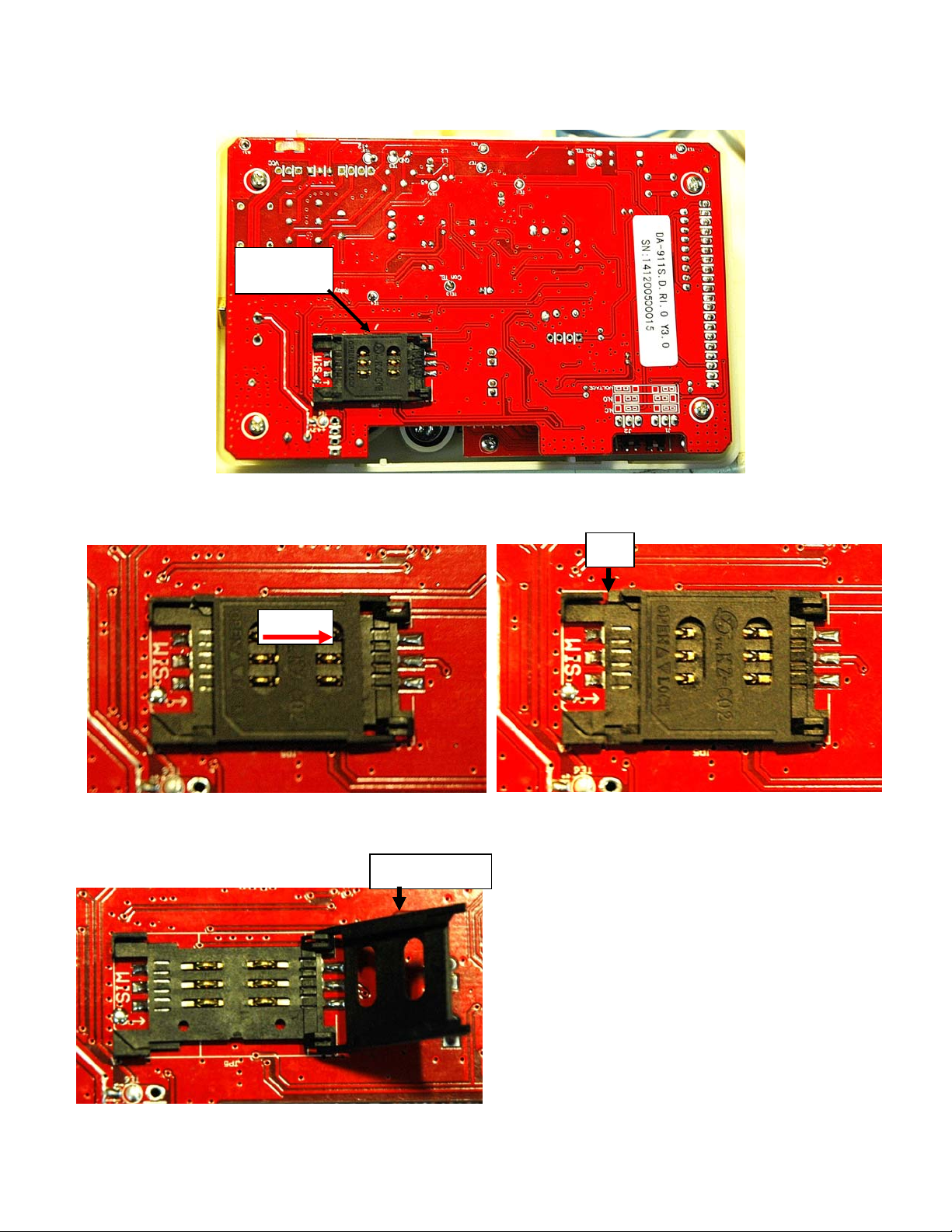
OPEN THE E-AVDS-GSM
There are four tabs that hold the case together. Two on the top side, and two on the bottom side. To open the case for Mini SIM card
installation, press down firmly on the seam of the case near the tabs on one side of the case and snap the case halves apart.
Tabs
2
INSTALL THE Mini SIM CARD
1. Set the case face-down on a clean surface. The Mini SIM card holder will be facing you.
2. Slide the top of the card holder to the right. A gap will appear between the top and bottom of the cardholder.
3. Flip the top frame up.
Mini SIM
card holder
gap
SLIDE
Top Frame

3
4. Insert the Mini SIM card into the slot on the top frame. The contacts should be facing you and the cut-off corner of the card should
be towards the right. Insert the card all the way in until it stops.
5. Fold the top frame back on top of the bottom. The card should set into the same-shaped recess in the bottom.
6. Slide the top frame to the left to lock the frame to the bottom.
If you need to record the IMEI number of the E-AVDS-GSM, see page 5 before re-assembling the case.
SLIDE
Cut-off corner
Card sets into
recess
4
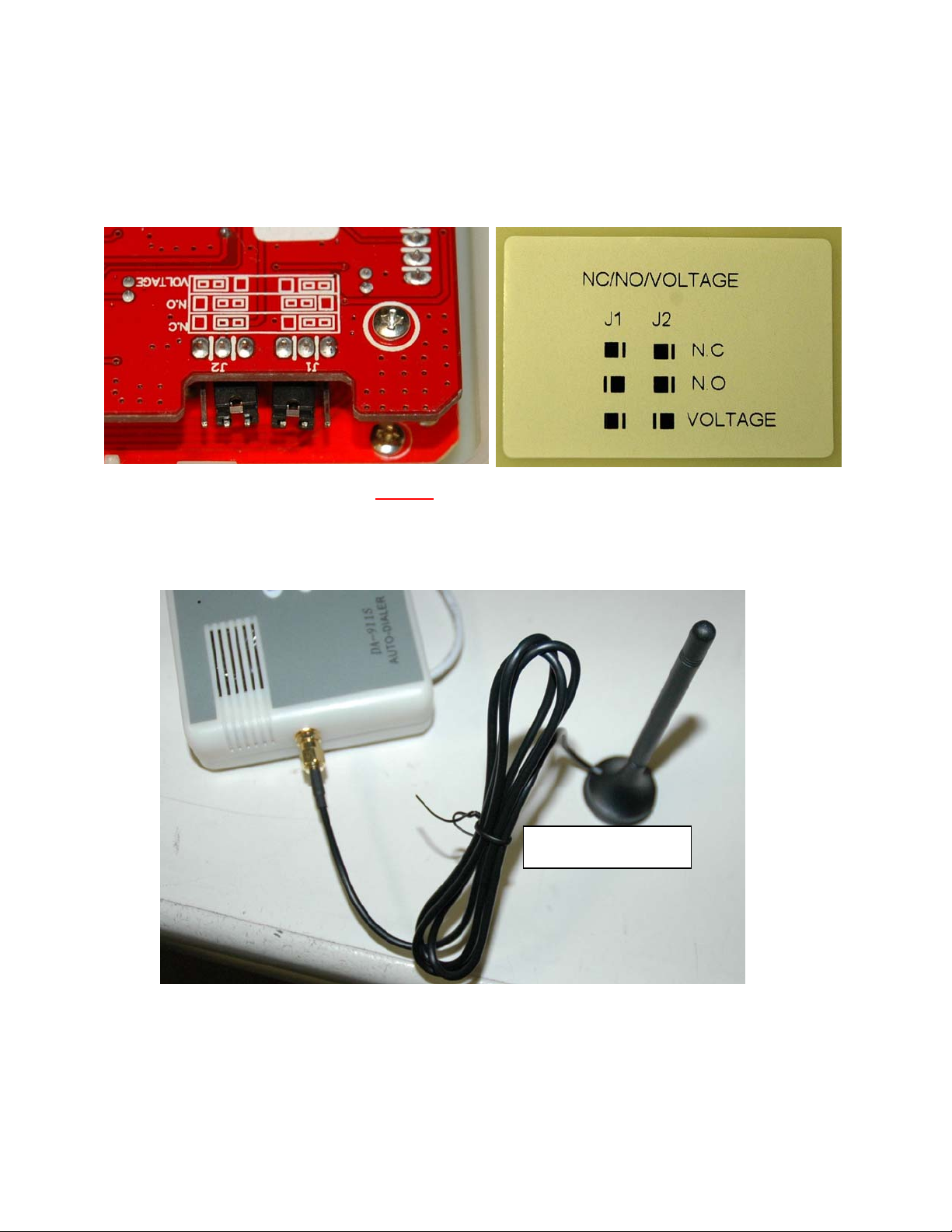
CONFIGURE THE JUMPERS
Configure the jumpers on the E-AVDS-GSM for connection to either the Normally-Closed (N.C.)or Normally-Open (N.O.) relay contact
on the E-xD. In the image below, the jumpers are set for connection to the N.O. terminal.
To set the “normal” relay state to Normally-Open, apply the J2 jumper to the center and right pin, and J1 jumper to the center and left
pin. In this configuration, a relay closure will trigger an alert state, activating the dialer.
To set the “normal” relay state to Normally-Closed, apply the J2 and J1 jumpers to the center and left pins. In this configuration, a
relay open condition will trigger an alert state, activating the dialer.
NOTE: The “VOLTAGE” jumper position is not used in conjunction with the E-xD.
With the Mini SIM card installed and the jumpers properly set, re-assemble the case and attach the supplied antenna to the port on the
side of the auto dialer.
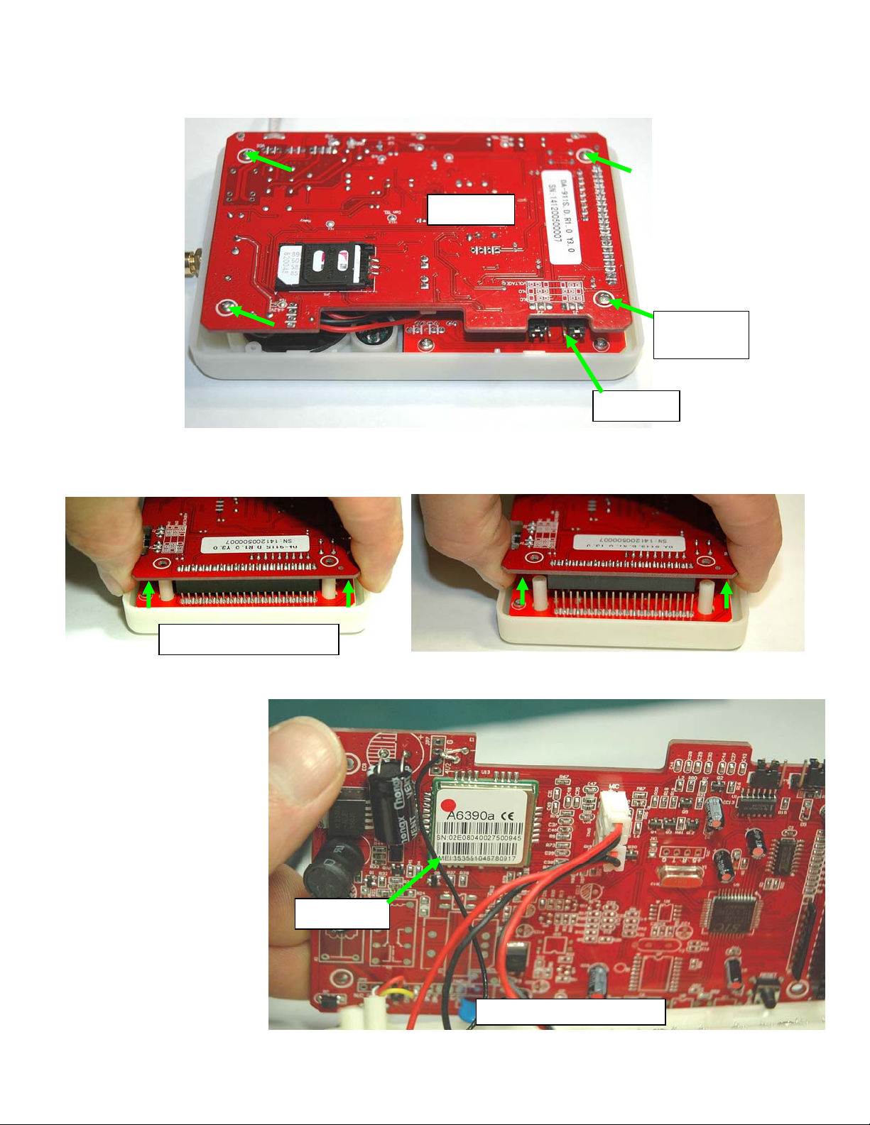
LOCATE THE IMEI NUMBER
Supplied antenna with
38” Cable
5
In some cases you will need to know what IMEI number is associated with your E-AVDS-GSM. Follow these steps to locate and
record the number.
1. While the case is still open (after installing the Mini SIM card), remove the 4 screws that secure the rear circuit board to the front
circuit board.
2. With the screws removed, carefully pull the rear circuit board off of the front circuit board. Lift the circuit board straight up to
separate them.
3. Gently lay back the circuit board and locate the IMEI number on the chip on the backside of the rear circuit board.
4. Record the IMEI number
and carefully re-assemble the
circuit boards.
Front PCB
Rear PCB
Remove
Screws (4 )
Separate the circuit boards
IMEI Number
Backside of rear circuit board
6
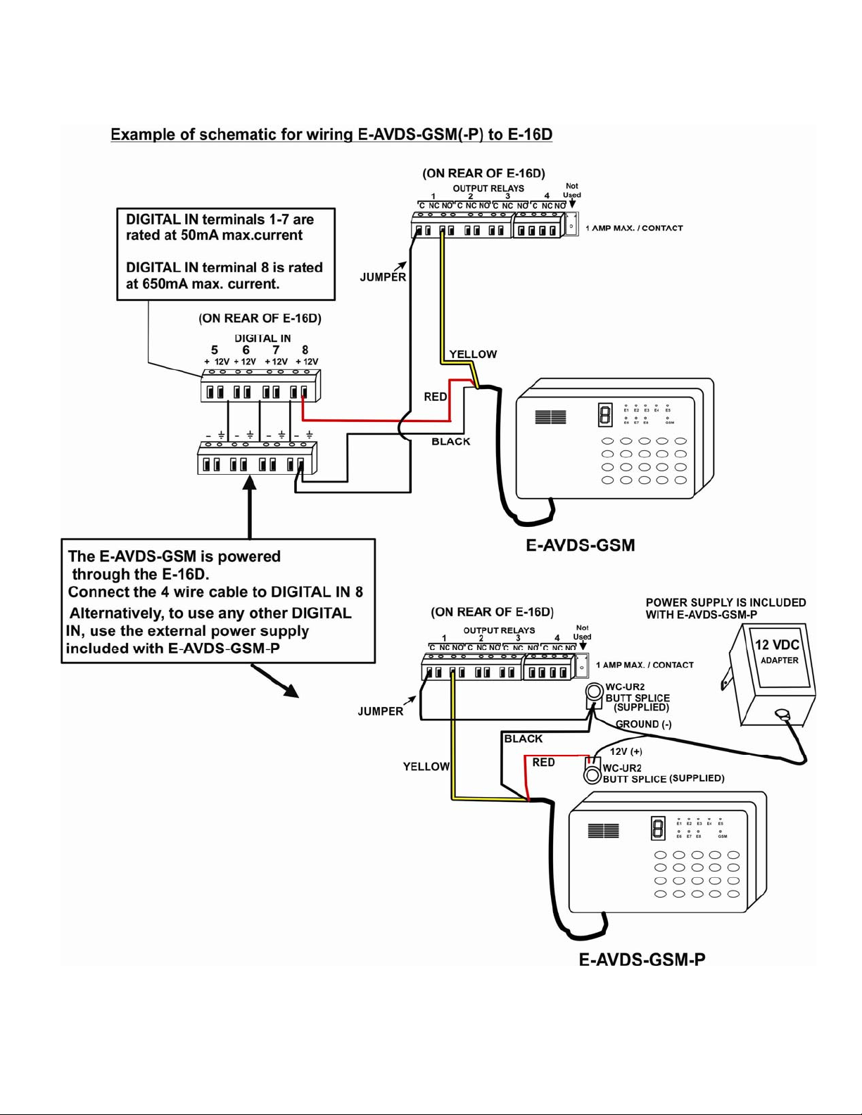
WIRING METHODS
Connect the cable from the E-AVDS-GSM to the E-xD according to one of the following diagrams:
Note: The attached cable is 27” long but can be extended up to 250 feet with any 3-conductor 22AWG (minimum) cable.

7
8
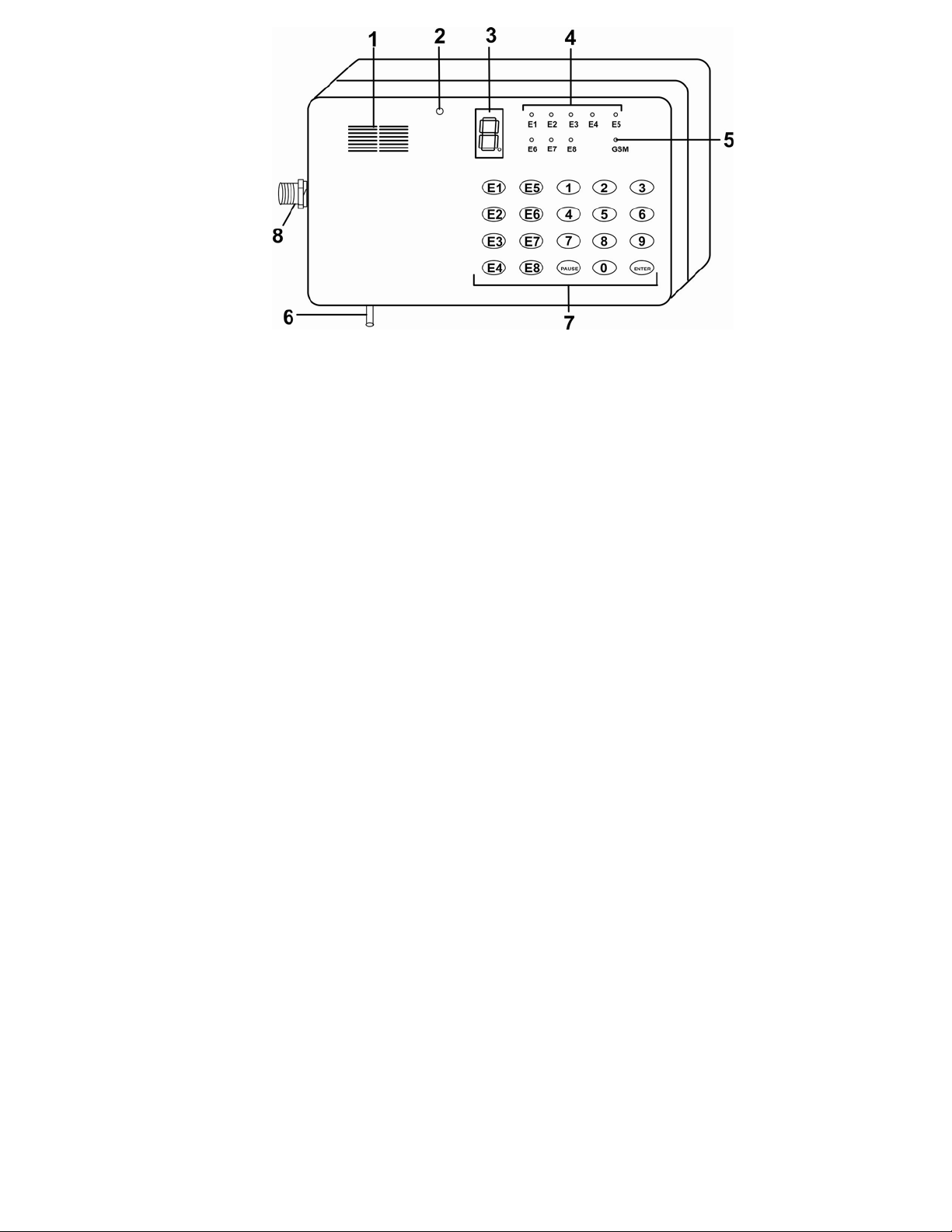
FEATURES
(1) Speaker
(2) Microphone
(3) LED 7-segment display- displays the number input and provides indicators for phone numbers.
When the dot of display blinks slowly, this means the GSM module is working normally;
When the dot of display blinks fast, this means the GSM module or SIM card is faulty\missing.
(4) “E1” – “E8” indicators: ON while setting E1-E8 phone/mobile phone numbers.
Note: E1 through E8 indicators will illuminate while setting the password.
(5) GSM indicator:
(a) LED OFF = GSM module power is OFF or doesn’t work
(b) 600ms (milliseconds) ON and 600ms OFF = SIM card has not been inserted /no signal/ in the network registration process.
(c) 75ms ON/3s (seconds) OFF = network register success, (control channel and user information exchange successful), GSM
module works normally.
(d) LED indicator ON = dialer is in alarm, alert triggering is in process.
(6) Connection Cable
red = 12V
black = Negative (ground)
white = Alert trigger
(7) Buttons: used to enter programming
(8) Antenna connection

9
E-AVDS-GSMConfiguration
By default, the E-AVDS-GSM will perform a self-test upon start up after which it will enter working state indicated by the display of a “1”
or “2” and a flashing decimal point on the lower right corner of LED display.
A slow flashing decimal point indicates normally working state.
A rapid flashing decimal point indicates there is no GSM communication.
If an SMS message and/or voice message have been programmed and saved, and a phone number and contact method have been
programmed into at least one “Ex” button, the E-AVDS-GSM will automatically alarm as soon as it receives an alarm signal.
Use the following to configure programming, enter or review phone numbers, program SMS messages and/or program voice
messages. (If GSM signal level is 0, please check antenna position and installation)
To exit programming mode at any time, press <ENTER>. The LED will display a “1” or “2” to indicate a normal working state.
1. Enter Programming Mode
Press <PAUSE> + private password (4 digits) + <ENTER>
Note: Default password: 0911
Example: PAUSE+0911+ENTER.
If password input is correct, “5” will be displayed and the dialer will enter the programming mode.
If password input is incorrect, “E” (meaning error) will be displayed and the dialer will return to a normal working state.
2. Program and Review Service Provider Contact Number
By default, the E-AVDS-GSM will automatically search for and program the contact number of the service provider when the unit is
powered ON.
To check that a number is programmed, in a programming state (in “5” state): press <3> and <0> . The dialer will display the service
provider phone number followed by two beeps.
To clear and refresh the service provider phone number, press <0> and then <ENTER>. The LED will display “A” to indicate a correct
input. It will then automatically search for and re-program the service provider contact number.
To manually enter the contact number, press <0> and then enter the service provider contact number, followed by <ENTER>.
For example: 0+15860305205+ENTER,
The display will return an “A” is the input has been done correctly.
We recommend letting the E-AVDS-GSM automatically acquire the service provider contact number.
3. Program Alarm Buttons and Alarm Method
This dialer supports two methods of reporting an alarm 1) voice alarm 2) SMS alarm
Up to 8 separate messages, voice and/or SMS, can be programmed to be sent when an alert is triggered.
In programming mode, press <E1>,<E2>…<E8> to select which one of the 8 programs will be configured. “三” will appear.
Enter the phone number to be dialed to reach the recipient of the message.
Press <ENTER>. The LED will display “A” if entered properly, “E” if incorrect.
Press <1> if a voice message will be sent or press <2> if an SMS message will be sent, followed by <ENTER>.
The LED will display “0” if entered properly, “E” if incorrect.
The dialer will then return to state “5”.
Example: E1+15860305205+ENTER+1+ENTER.
This programs button E1 with a phone number to receive a voice message.
To delete the programming on any button, press the numbered <Ex> button (<E1> – <E8>) followed by the <ENTER> button.
To review the saved number and corresponding alarm method:
In programming mode, press <3> and then the <Ex> button to be reviewed. The programmed phone numbers and corresponding
alarm method will be displayed.
Example: 3 + E1/E2/E3/E4 .
The LED will display alarm method (1 for voice or 2 for SMS)→”A” →numbers in the phone number, followed by two beeps
when finished.

10
4. Save and Review Voice Messages
This dialer supports voice messages up to 20 seconds in length. (Shorter message have the best quality).
In programming mode (“5” displayed), press <1> ( “『” displayed means to begin recording.), and then begin speaking into the
microphone. Speak clearly and within 6 inches of the microphone for the best sound quality. When the recording times out, two
beeps will be heard. (To end the voice message recording manually, press <8> when finished.) The recording will then be played back
to you.
Review the Recorded Voice Message,
In programming mode, press <3> + <1> . A “P” will be displayed indicating the message being played. When finished, two beeps will
be heard.
5. Program SMS message
To program an SMS message to be sent by the E-AVDS-GSM, you must first send the message to the
E-AVDS-GSM via text message.
A. In programming mode, press <2>.
B. From a phone with a text messaging feature, send a message not more than 70 characters in length (any additional characters
will be ignored by the dialer) to the SIM card. (The phone number of the SIM card should have been provided by the service
provider that sold you the SIM card.)
C. Upon receipt, the LED will display “A” and two beeps will be heard. It will then return to programming mode (“5”).
If this takes too long and the process times out, an “E” will be displayed. Wait 2 minutes and then repeat the procedure.
Note: The buttons on the dialer are not operable while waiting for message content. You will need to wait 2 minutes if the
dialer times out.
The failure of the dialer to receive the message may be caused by a loss of communication. If repeated attempts fail, try
power-cycling the dialer, allow it to restore connection with the service provider, and try this procedure again.
If no SMS message is programmed, the default SMS message sent will be “DA-911 ALARM”.
6. Test Programmed Alarm
In programming mode, press <4> and then the desired <Ex> button to be tested. The display will illuminate the upper 4 segments in a
small “o” during the test. The test will last 15 minutes. Check the device dialed for the message that was sent. (For SMS messages,
this may take several minutes.) To cancel the test, press <ENTER>.
If “0 “appears, this indicates a successful test and then system will return to state “5”.
If “E” appears, this indicates the communication attempt failed and the dialer will then return to programming mode (“5”). Try the test
again.
If test fails after repeated attempts:
verify the phone number entered is correct.
make sure the SIM card is properly installed
verify the service number provider contact number is correct,
verify the SIM card/mobile phone is in service
check the GSM antenna connection and that the signal quality is normal.
7. Program Voice Alert Stop Method
In programming mode, press <5> and then input 0/1/2 (desired stop method (described below)), and <ENTER>. The “A” will be
displayed to confirm correct input, and then return to state “5”.
Example: 5 + 0 + ENTER.
Three Methods to Stop Voice Alert Messages:
Method 0. Messages will automatically stop once the recipient picks up the line called. If they do not pick
up, the number will be called again according to the number of retries that are programmed (See Section 8).
Method 1. Call recipient can press <8> on phone to stop repeated attempts to that phone number after
receiving an alarm call.
Method 2. Call recipient can press <9> on phone to stop repeated attempts to that phone number and calls to
all other recipients programmed in the dialer.

11
Review Voice Alert Stop Method Programmed
In programming mode, press <3> and then <5>.
The 7-segment display will show 0, 1 or 2 followed by two beeps .
Note: When receiving an alert call, it is better to press <8> or <9> after the voice message has played after which you will
immediately hear two beeps. Then, if the stop command was successful, the user will hear a long beep.
8. Program and Review Alert Retries
In programming mode, press <6>, then enter the number of times the dialer should retry a number after a failed call
(enter 0-9), followed by <ENTER>. If entered correctly, the LED will display “A”, then return to programming mode (“5”). The
default number of retries is 5.
Note: If you enter “0”, the dialer will retry an unlimited number of times.
Review Number of Programmed Retries
In programming mode, press <3> and then <6>.
The 7-segment display will show the number of retries programmed (0-9) followed by two beeps .
Note: For SMS alert messages, dialer will stop if the message was sent successfully. It will not follow the programmed
number of retries.
9. Save and Review Password
The dialer supports a 4-digit private password. (Default password is 0911) To change the default password, first enter programming
mode. Then press <PAUSE> , 4 digits, followed by <ENTER>.
Example: If the desired private password is 1234, press <PAUSE> + <1><2><3><4> + <ENTER>.
E1 through E8 LED indicators will illuminate while setting the password.
The dialer will beep twice and display a “0” indicating you have finished and the number has been accepted. The dialer will then
return to programming mode displaying a “5”.
If you enter more or less than 4 digits, system will display “E” and return to state “5”.
Review Password
In programming mode, press <3>. and then <PAUSE>. The LED will display the numbers in the password, followed by two beeps.
Note: If the user loses the programmed password, open the back cover and press the “RESET” button (see picture) using a
non-conductive (wood, plastic) object. Password will be changed to the default “0911”, but no other information/settings
will be lost. After pressing, the dialer will beep 3 times to indicate a reset.
Password Reset Button

12
10. Program and Review Length of Time Alert Trigger Will Last
In programming mode, press <7> and input triggering time:
<1> = .5 seconds
<2> = 3 seconds
and then press <ENTER>. If entered correctly, the LED will display “A”, then return to programming mode (“5”).
Review Alert Trigger Duration
In programming mode, press <3> and <7>
The LED display will show the triggering time programmed (1 or 2), followed by two beeps.
Note: The default triggering time is 0.5s.
11. GSM Module Signal Strength Display
In normal operating mode (not programming mode), with the decimal point on the lower right corner flashing slowly, press <5> + <6> +
<ENTER> to switch ON the GSM module signal strength display.
The value will be 0-5, with 0 indicating the weakest (unable to send an alert) and 5 indicating the strongest signal.
12. Stop Alarm State on Dialer
While triggered, the E-AVDS-GSM will automatically send an alarm by dialing the numbers saved. If a user wants to stop it, enter the
password while the small “o” (upper segments of the LED display) is displayed. If the password is accepted, the password will then
be displayed, the alarm state will be discontinued, and two beeps will be heard. The E-AVDS-GSM will return to normal operating
mode.
If the user enters the wrong code, the dialer will remain in an alarm state.
13. Restore Factory Default Settings
In programming mode, press <8> + <9><1><1> + <ENTER>. The LED will display “A” if entered correctly and
and return to programming state (“5”).
Note: Most of the settings can be restored to factory default, except for the voice message recorded and triggering method (Need
manually operation).
14. Extra Information
1. If a SIM card is not installed or the E-AVDS-GSM is faulty, the LED will display “E” after initialization and will not function.
2 Press <ENTER> to return to working state after finishing any programming operation. If <ENTER> is not pressed and the LED
continues to display “5” (programming mode), the dialer will not be able to acknowledge any alert triggers until it is returned to a
working state.
3. Do not use a SIM card with a PIN code protection feature. If the SIM card has this feature, insert the card in
another mobile phone to disable the function (for example: using a Nokia mobile phone, choose: Menu→setting →
security setting→PIN protection →OFF).

13
QUICK OPERATION LIST
1. To enter programming mode: Press <PAUSE> + password + <ENTER> . LED will display “5” if password is correct and remain in
programming mode, and display “E” if password is incorrect and return to working state.
2. In normal working state, a user can display the GSM signal strength by pressing <5> + <6> + <ENTER> . “0” means weak, “5”
means strong. Press <ENTER> again to return to working state.
3. In alarm state (small “o” displayed in LED), user can input correct password to withdraw the alarm. The dialer will immediately
return to a working state, ready to respond to another trigger.
4. Below is a chart for user quick reference. For detailed explanation, see instructions in this manual.
While in programming mode (“5” displayed in the LED), the following functions will work:
Operation Function Description Display
PAUSE +password+
ENTER
Edit password, must be 4
digits After <PAUSE>,”P” appears;
After successful entry “0” appears and the unit beeps twice
After failed entry “E” appears
3 + PAUSE Inquire password Input Press <3>,“[ ”appears;
Press <PAUSE> password appears
E1 + phone number +
ENTER + 1 / 2 + ENTER Store/edit the alert recipient
phone number and alarm
receiving method
Press <E1>,“三” appears;
Input phone number,“A” will appear;
Enter message method (Voice (1) or SMS (2))
Press <ENTER> “0” will appear.
3 + Ex Review phone number and
alarm receiving method Display alarm means (1 or 2), “A” , then phone number,
followed by two beeps
4 + Ex Test the recipient phone
number and alarm receiving
method
Display “A” if successful
Display “E” if failure
Press <ENTER> to exit test.
1 record voice message Input After pressing <1>, “「” will appear;
When recording is complete, hear two beeps
The recording will playback
3 + 1 Play recorded voice message “P” will display during play back
2 Edit SMS message After pressing <2>, send text message to dialer.
Display “A” if successful
Display “E” if failure
0 + Service Provider Contact
Number + ENTER Enter Service Provider
contact number Display “A” if successful
0 + Enter Delete Service Provider
contact number Display “A” if successful
3 + 0 Review Service Provider
contact number Displays contact number followed by two beeps
5 + 0/1/2 + ENTER
Program method of stopping
alert method after receiving it Display “A” if successful
3 + 5 Review method of stopping
alert Displays 0, 1 or 2 followed by two beeps
6 + 0-9 + ENTER Program number of alert
retries to attempt Display “A” if successful
3 + 6 Review number of retries
programmed After enter <3> a “C” will display
After enter <6> the number of retries programmed will
display
7 + 1 / 2 + ENTER Program duration of alert
trigger Display “A” if successful
3 + 7 Review duration of trigger
programmed Display “1” or “2” followed by two beeps
8 + 9 + 1 + 1 + ENTER Reset factory default settings Display “A” if successful
ENTER Exit programming mode,
resume normal working state
14
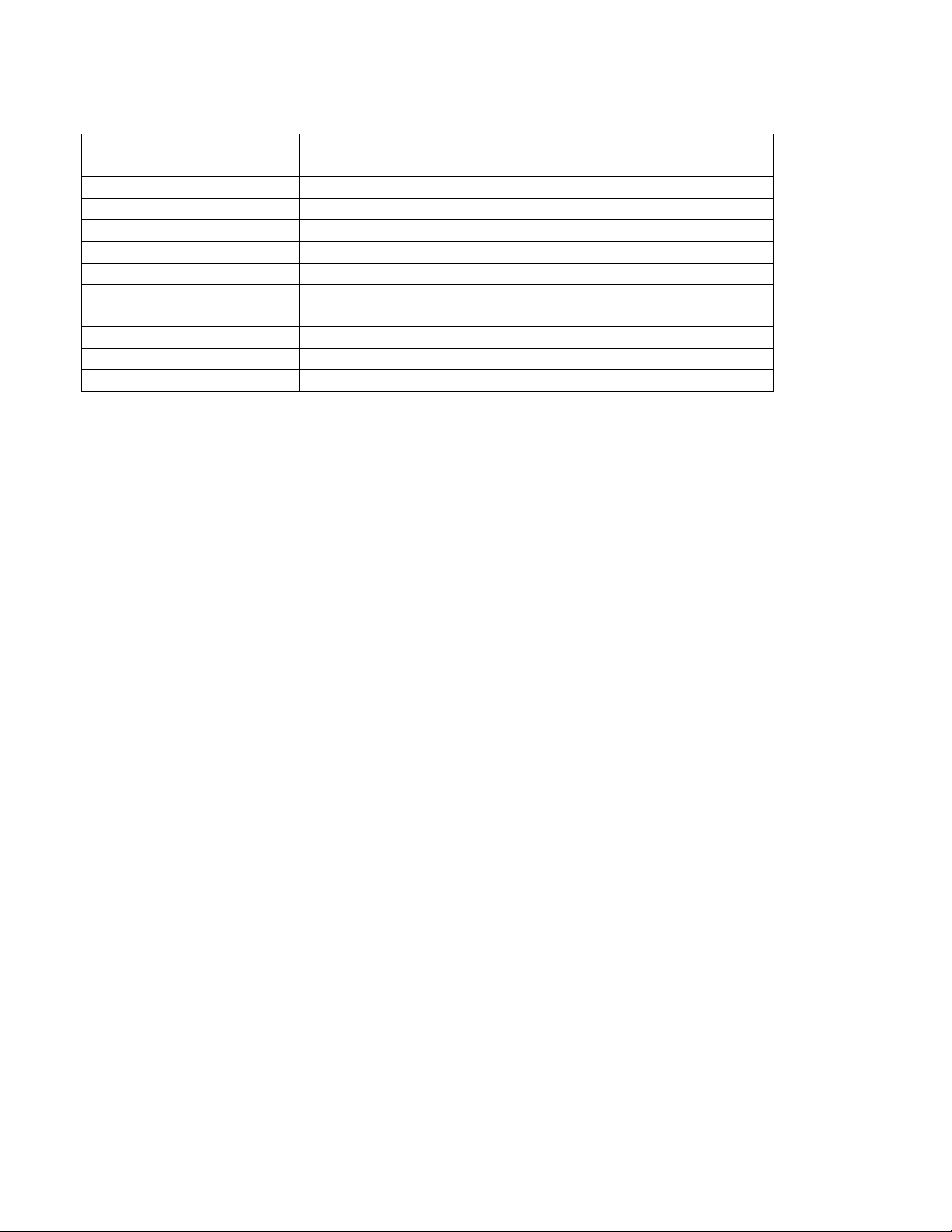
SPECIFICATIONS
Voltage DC 11V to 15V
Static current 40mA (Based on operating voltage: DC 12V)
Operating current 250mA (MAX) (Based on operating voltage: DC 12V)
Triggering mode N.C, N.O or voltage signal
Triggering duration 0.5 seconds or 3 seconds (default is 0.5s)
Voice recording 20 seconds maximum
Phone numbers Up to 8 contact numbers
Private password protection 4-digit private password programmable
Default password = 0911
Message support Voice or SMS text (max. 70 characters)
Alarm state duration 15 minutes
Communication method GSM network. GSM frequency: 900/1800Mhz or 850/900/1800/1900Mhz
MAN235 Rev 6/13/18
This manual suits for next models
1
Table of contents


