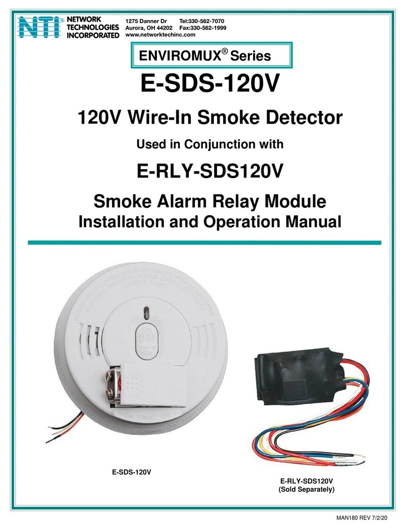
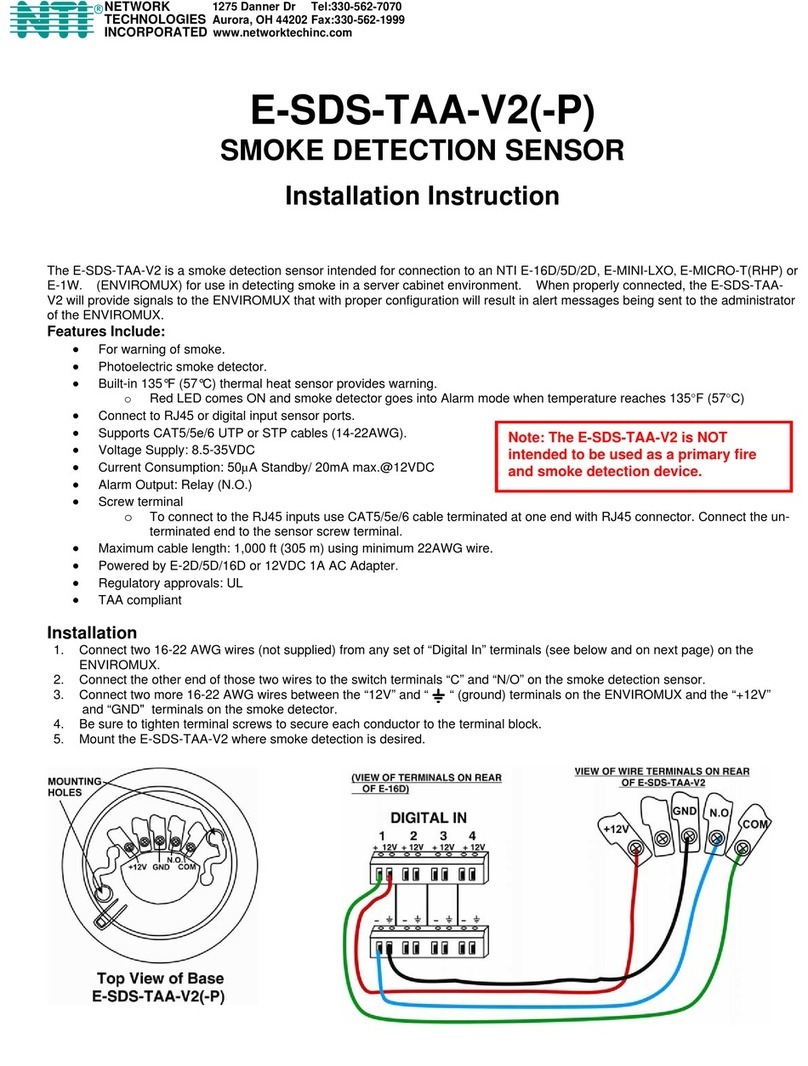
NTI E-SDS User manual

1
Model Regulatory
Approvals 12VDC
adapter
E-SDS UL No
E-SDS-PA UL Yes
E-SDS-CE CE,RoHS No
E-SDS-CEPA CE,RoHS Yes
E-SDS-CE-E7 CE,RoHS No
E-SDS(-CE)
E-SDS(-CE)PA
SMOKE DETECTION SENSOR
Installation Instruction
The E-SDS(-CE) is a smoke detection sensor intended for connection to an NTI Enterprise Environment Monitoring System (SYSTEM)
for use in detecting smoke in a server cabinet environment. When properly connected, this sensor will provide signals to the
SYSTEM that with proper configuration will result in alert messages being sent to the administrator of the SYSTEM. The E-SDS(-CE)
has screw terminals for easy user connections.
Options:
E-SDS-PA also includes a 12VDC (regulated) AC adapter with country-specific line cord (add “-PA” to the model
number).
E-SDS-CE(PA): CE certified (add “CE” to the
model number
E-SDS-CE-E7: CE certified model with pre-wired
7 foot cable and coupler (can be extended 1000 ft with 24AWG
CATx cable) for plug-in to RJ45 Sensor port or wired pigtail to a
Digital Input.
Disconnect the Base
Remove the base from the detector head. To remove the base, locate the long and short alignment marks on the side of the base.
When the detector head is locked to the base, the alignment mark on the detector head lines up with the long alignment mark on the
base (see image below). To release the base, rotate the base to align the shorter alignment mark on the base with the mark on the
detector head. Once they are aligned, pull the detector head apart from the base.
Install the Base
Mount the base of the E-SDS(-CE) where smoke detection is desired.
N
ote: The
E
-SDS(-CE)(PA) is NOT
intended to be used as a primary fire
and smoke detection device.

2
Switch Contact Connection
1. Connect two 18-22 awg wires (not supplied) to “Digital In” terminals on the E-16D (sets 1-8) , “Digital In” terminals on the E-MINI-
LXO, E-2D and E-5D (sets 1-5) or any set of dry contacts on the
E-MINI (set 1, 2, 3 or 4).
2. Connect the other end of those two wires to the smoke detection sensor base at terminal set 1-6 and 3-4.
Power Connection
For Model E-SDS(-CE):
1. Connect two 18-22awg wires (not supplied) between the E-16D and the E-SDS(-CE) as shown below.
(Wiring for E-2D and E-5D also shown.)
a. Connect one wire between “12V” on the SYSTEM and terminal 2 on the smoke detector.
b. Connect the other wire between “ “ (ground) on the SYSTEM and terminal 5 on the smoke detector.
2. Be sure to tighten terminals to secure each conductor.
The E-SDS(-CE)
draws 30mA @ 12VDC

3
For Model E-SDS-(CE)PA:
When a 12VDC power supply is not available on the SYSTEM (for example, E-MINI and E-MINI-LXO do not include terminals to
provide 12VDC power to sensors), model E-SDS-(CE)PA can be used.
1. Connect the AC adapter wire labeled “PLUS 12” to terminal 2 on the smoke detection sensor.
2. Connect the AC adapter wire labeled “NEG” to terminal 5 on the smoke detection sensor.
3. Add a jumper wire between terminals 5 and 6 on the smoke detector.
4. Be sure to tighten terminals to secure each conductor.
Wired using this method the smoke detector must be manually power-cycled in order to reset it when it goes into alert.
Wired using this method the smoke detector can be power-cycled through the web interface when it is in alert. Make sure
that no sensors are configured to activate the output relay when in or out of alert. (See page 7)

4
For Model E-SDS-CE-E7:
The E-SDS-CE-E7 includes a 7 foot pre-wired cable with RJ45 connector (wiring shown below) for plug in to either an available RJ45
Sensor port in an E-2D/5D/16D or into a pigtail wired to a Digital Input on an E-2D/5D/16D. No additional power supply is required.
The 7 foot cable can be extended to up to 1000 feet using a CAT5 patch cable (minimum 24AWG) using the supplied RJ45 coupler.
The E-SDS(-CE)
draws 30mA @ 12VDC

5
To wire your own CATx patch cable to an E-SDS(-CE) sensor, follow the wiring instruction below.
Note: When connected to an RJ45
Sensor port, a smoke detector in
alarm must be manually
disconnected and reconnected in
order to reset it.
The E-SDS(-CE)
draws 30mA @ 12VDC

6
Install the head
1. Align the raised line on the head to the short raised line on the base as shown below.
2. Rotate the head clockwise until the raised line on the head aligns with the longer raised line on the base.
Operation
1. Connect the AC adapter to a 100-240VAC power source. The LEDs on the E-SDS(-CE) will
blink red to indicate the sensor is functioning and in status-ready condition. The LEDs will
illuminate solid red when smoke is detected.
2. Configure the SYSTEM to report signals from the connected dry contact sensor as smoke detection
sensor alerts. (Refer to SYSTEM manual for details on configuration- see also examples on next
pages.) When smoke is detected, the switch terminals on the E-SDS(-CE) will close
to generate an alert message.
For maintenance and testing instruction, see the instructions that are included from the sensor
manufacturer with this kit.
Cycle Sensor Power on E-xD Models
When the smoke detection sensor senses smoke and an alert condition is triggered, in order to reset the smoke detector to a ready
state after the presence of smoke has been resolved, the smoke detector must be power-cycled.
A “Cycle Sensor Power” button (below) is provided for each sensor connected to the “Digital In” terminals on the
E-16D (locally-connected Digital Inputs only). To momentarily disrupt power to any sensor connected to a Digital Input terminal, click
on this button. The 12VDC power will be disrupted to the sensor for 5 seconds and then automatically restored.
Note: On E-5D and -2D, the “Cycle Sensor Power” will cause the “AUX PWR” terminals to cycle power. This will only be
effective for the smoke detection sensor if the sensor is being powered from these terminals. If your sensor is powered, for
example, from an AC adapter, the “Cycle Sensor Power” button will have no effect on that sensor, but it will still cycle power
on the “AUX PWR” terminals, disrupting any device getting power from these terminals for 5 seconds. Keep this in mind if
more than one sensor (or device) is being powered from these terminals.
SHORT ALIGNMENT MAR
K
LONG ALIGNMENT MAR
K
DETECTOR
HEAD
LED
RAISED ALIGNMENT LINE
Cycle Sensor Power

7
Application Note:
A smoke detector connected to an RJ45 Sensor Port does not have “Cycle Sensor Power” button and must be manually disconnected
(unplugged) and reconnected in order to reset it. To use this feature, make sure the smoke detector is wired to a Digital Input.
Cycle Sensor Power on E-MINI-LXO
The power to the smoke detector can also be power-cycled on the E-MINI-LXO when wired as shown on the lower image on page 3. If the output
relay is used to control power to the smoke detector, the output relay can be manually activated (to open power to the smoke detector) and then
deactivated (to restore power to the smoke detector.
When wired in this fashion, make sure that none of the sensors are configured to have the output relay status change to “Active”. Both fields (below)
must be set to “Inactive”. Otherwise, when the relay is active the smoke detector will be powered OFF.
Make sure the Output Relay status for both fields in all sensor configurations
is set to “Inactive” if the output relay is used to power the smoke detector.
To power-cycle the smoke detector using the web interface, set the output to
“Activate”, click “Apply Changes”, then set to “Deactivate” and click “Apply
Changes” again.

8
Example of sensor configuration in E-MINI-LXO

9
Example of sensor configuration in E-16D/-5D/-2D
Example of sensor configuration in E-MICRO-T(RHP)_

10
Warranty Information
The warranty period on this product (parts and labor) is two (2) years from the date of purchase. Please contact Network
Technologies Inc at (800) 742-8324 (800-RGB-TECH) or (330) 562-7070 or visit our website at http://www.networktechinc.com for
information regarding repairs and/or returns. A return authorization number is required for all repairs/returns.
COPYRIGHT
Copyright © 2007, 2019 by Network Technologies Inc. All rights reserved. No part of this publication may be reproduced, stored in a
retrieval system, or transmitted, in any form or by any means, electronic, mechanical, photocopying, recording, or otherwise, without
the prior written consent of Network Technologies Inc, 1275 Danner Drive, Aurora, Ohio 44202.
CHANGES
The material in this guide is for information only and is subject to change without notice. Network Technologies Inc reserves the right
to make changes in the product design without reservation and without notification to its users.
Man125 Rev 6/17/19
Note: The E-SDS(-CE)(PA) is NOT intended to be used as a primary fire and smoke
detection device.
This manual suits for next models
4
Table of contents
Other NTI Smoke Alarm manuals