NTI E-SDS-TAA-V2 User manual

E-SDS-TAA-V2(-P)
SMOKE DETECTION SENSOR
Installation Instruction
The E-SDS-TAA-V2 is a smoke detection sensor intended for connection to an NTI E-16D/5D/2D, E-MINI-LXO, E-MICRO-T(RHP) or
E-1W. (ENVIROMUX) for use in detecting smoke in a server cabinet environment. When properly connected, the E-SDS-TAA-
V2 will provide signals to the ENVIROMUX that with proper configuration will result in alert messages being sent to the administrator
of the ENVIROMUX.
Features Include:
For warning of smoke.
Photoelectric smoke detector.
Built-in 135°F (57°C) thermal heat sensor provides warning.
oRed LED comes ON and smoke detector goes into Alarm mode when temperature reaches 135°F (57°C)
Connect to RJ45 or digital input sensor ports.
Supports CAT5/5e/6 UTP or STP cables (14-22AWG).
Voltage Supply: 8.5-35VDC
Current Consumption: 50µA Standby/ 20mA max.@12VDC
Alarm Output: Relay (N.O.)
Screw terminal
oTo connect to the RJ45 inputs use CAT5/5e/6 cable terminated at one end with RJ45 connector. Connect the un-
terminated end to the sensor screw terminal.
Maximum cable length: 1,000 ft (305 m) using minimum 22AWG wire.
Powered by E-2D/5D/16D or 12VDC 1A AC Adapter.
Regulatory approvals: UL
TAA compliant
Installation
1. Connect two 16-22 AWG wires (not supplied) from any set of “Digital In” terminals (see below and on next page) on the
ENVIROMUX.
2. Connect the other end of those two wires to the switch terminals “C” and “N/O” on the smoke detection sensor.
3. Connect two more 16-22 AWG wires between the “12V” and “ “ (ground) terminals on the ENVIROMUX and the “+12V”
and “GND" terminals on the smoke detector.
4. Be sure to tighten terminal screws to secure each conductor to the terminal block.
5. Mount the E-SDS-TAA-V2 where smoke detection is desired.
NETWORK
TECHNOLOGIES
INCORPORATED
Tel:330-562-7070
Fax:330-562-1999
1275 Danner Dr
Aurora, OH 44202
www.networktechinc.com
NTI R
N
ote: The E-SDS-TAA-V2 is NOT
intended to be used as a primary fire
and smoke detection device.

Alternative Power Supply
If the 12V power on the ENVIROMUX is unavailable, an E-SDS-TAA-V2-P will be needed that includes a 12VDC AC adapter.
Connect the 12VDC AC adapter (sold separately) as follows:
1. Connect the wire labeled “PLUS 12” to the terminal marked “+12V” on the smoke detection sensor.
2. Connect the wire labeled “NEG” to the terminal labeled “GND“ on the smoke detection sensor.
Be sure to add jumper between "GND" and "COM" terminals when external 12VDC power supply is used.

Alternative Sensor Connection
If a connection to an available “RJ45 Sensor” input is desired,
CAT5/5e/6 patch cable can be used (minimum 16-22AWG) by
cutting off one end and terminating to the sensor as illustrated
to the right.

Operation
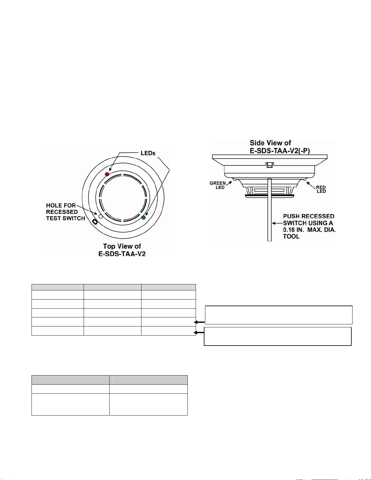
1. When powered ON, after a short delay (15 seconds) the LEDs on the E-SDS-TAA-V2 will flash (one will be green, the other red)
once every 10 seconds for up to 4 minutes (see TABLE 2 below) after which only the Green LED will blink every 5 seconds to
indicate the sensor is functioning and in status-ready condition.
When smoke is detected or when the temperature exceeds 135°F (57°C) the Red LED will illuminate solid red and the detector will
be placed in Alarm Mode (closing the circuit between N.O. and COM terminals).
To reset the smoke detector to Normal Mode, cycle power to the detector.
Test Switch
An opening for a recessed test switch is located on the detector housing.
1. Insert a small screwdriver or Allen wrench (0.18˝dia. max.) into the test switch opening; push and hold.
2. If the detector is working properly, the detector’s red LED should light within five seconds. To reset the smoke detector to
Normal mode, cycle power to the detector.
TABLE 1: DETECTOR LED MODES
Mode Green LED Red LED
Power-up Blink every 10 sec Blink every 10 sec
Normal (standby) Blink every 5 sec ---
Out of sensitivity --- Blink every 5 sec
Freeze Trouble --- Blink every 10 sec
Alarm --- Solid ON
After an initial power-up delay, the red and green LEDs will blink synchronously once every ten seconds. It will take approximately
80 seconds for the detector to finish the power-up cycle (see Table 2).
TABLE 2: POWER-UP SEQUENCE FOR LED STATUS INDICATION
Condition Duration
Initial LED Status Indication Up to 80 seconds
Initial LED Status Indication if
excessive electrical noise is
present
Up to 4 minutes
NOTE: If, during power-up, the detector determines there is excessive electrical noise in the system such as those caused by
improper grounding of the system or the conduit, both LEDs will blink for up to 4 minutes before displaying detector status (see
Table 2).
Red LED will blink every 10 seconds if the E-SDS-
TAA-V2 senses a temperature below 5˚C (41˚F)
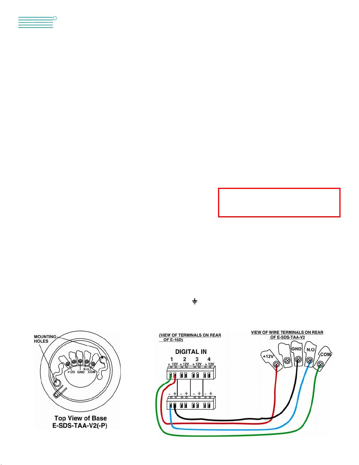
The on-board switch will also close the circuit
between N.O. and COM contacts in Alarm Mode

2. Configure the ENVIROMUX to report signals from the connected sensor as smoke detection sensor alerts. (Refer to
ENVIROMUX manual for details on configuration- see also example below.) When smoke is detected, the switch terminals on the
E-SDS-TAA-V2 will close to generate an alert message from the ENVIROMUX.
For maintenance and testing instruction, see the instructions that are included from the sensor
manufacturer with this kit.
Example of sensor configuration in ENVIROMUX
In the event the smoke detector should be placed in alarm condition, it must be power-cycled in order to reset it. To quickly cycle
the power when connected to a Digital Input of an E-xD, go to the sensor status page in the ENVIROMUX WEB interface, and click
on the “Cycle Sensor Power”button. (Not applicable to E-MINI-LXO,E-MICRO-T(RHP) or E-1W.) The 12VDC power will be
disrupted to the sensor for 5 seconds and then automatically restored.
Cycle Sensor Power
(E-xD only)

Warranty Information
The warranty period on this product (parts and labor) is two (2) years from the date of purchase. Please contact Network
Technologies Inc at (800) 742-8324 (800-RGB-TECH) or (330) 562-7070 or visit our website at http://www.networktechinc.com for
information regarding repairs and/or returns. A return authorization number is required for all repairs/returns.
COPYRIGHT
Copyright © 2007, 2019 by Network Technologies Inc. All rights reserved. No part of this publication may be reproduced, stored in
a retrieval system, or transmitted, in any form or by any means, electronic, mechanical, photocopying, recording, or otherwise,
without the prior written consent of Network Technologies Inc, 1275 Danner Drive, Aurora, Ohio 44202.
CHANGES
The material in this guide is for information only and is subject to change without notice. Network Technologies Inc reserves the
right to make changes in the product design without reservation and without notification to its users.
MAN346 Rev 9/13/19
Note: The E-SDS-TAA-V2 is NOT intended to be used as a primary fire and smoke
detection device.
This manual suits for next models
1
Table of contents
Other NTI Smoke Alarm manuals
Popular Smoke Alarm manuals by other brands

AMC
AMC 800 Series manual

Bosch
Bosch D263TH installation instructions

Ei Electronics
Ei Electronics Heat Alarm Ei 103R Technical specifications

ELRO
ELRO FZ500221R instruction manual

Edwards Signaling
Edwards Signaling 517T Series installation instructions

DSC
DSC WS4926 Series Installation and operating instructions