Det-Tronics SmokeWatch U5015 User manual

3.5
95-8723
Instructions
Det-Tronics SmokeWatch™Explosion Proof Smoke Detector
U5015

Table of Contents
OVERVIEW ..........................1
FEATURES ..........................1
BENEFITS ...........................1
SPECIFICATIONS .....................2
OPERATION .........................3
Warm Up ..........................3
Outputs ...........................3
Integral Wiring Compartment ..........4
LED ..............................4
Latching...........................4
Non-Latching.......................4
Continuous Self-Test.................4
Manual Self-Test ....................4
IMPORTANT SAFETY NOTES ...........5
INSTALLATION .......................5
Grease / Lubrication .................5
Identication of Detector Mounting
Locations..........................5
Protection Against Moisture Damage....6
Power Supply Requirements ..........6
Transp or t Cover ....................6
Mounting Location Options............6
Mount the Detector ..................7
Wiring Cable Requirements ...........7
Jumper ...........................7
Wiring Procedure ...................8
MAINTENANCE .......................9
Routine Inspection ..................9
DEVICE REPAIR AND RETURN.........13
ORDERING INFORMATION ............13
Spare Parts .......................13
Accessories.......................13
U5015 Model Matrix ................13
APPENDIX A – FM APPROVAL
DESCRIPTION ....................14
APPENDIX B – CSA APPROVAL
DESCRIPTION ....................15
APPENDIX C – IECEx APPROVAL
DESCRIPTION ....................16
APPENDIX D – ADDITIONAL APPROVALS
DESCRIPTION ....................17

195-8723
3.5
WARNING
Be sure to read and understand the entire
instruction manual before installing or
operating the smoke detection system. Any
deviation from the recommendations in this
manual may impair system performance
and compromise safety.
OVERVIEW
The Det-Tronics SmokeWatch™U5015 Explosion
Proof Smoke Detector has Division and Zone
explosion-proof ratings and is suitable for industrial
and commercial applications. The detector is
designed to operate effectively with smoldering
and rapidly growing fires and contains the ability to
annunciate faults ensuring no undisclosed failures.
The SmokeWatch U5015 Smoke Detector outputs
include 0-20 mA, a localized LED, and relays.
Typical applications that use the U5015 include:
– Combustible storage facilities
– Munitions manufacturing
– Volatile chemical storage
– Chemical processing plants
– Petroleum refineries
– Turbine enclosures
– Battery rooms
– HVAC applications
The hot-swappable sensor module is intrinsically
safe and allows live maintenance while under
power, without de-classifying the hazardous area.
The integrated junction box is available in a
variety of port configurations for simplified wiring
and installation. See Figure 1 for all the U5015
Smoke Detector components.
FEATURES
• FM Approved for use in Class I, Division 1
hazardous locations
• FM Approved for smoke detection performance
• IECEx Zone approved
• Trouble-free photoelectric operation
• 0-20 mA output for DCS integration
• Self-checking circuitry ensures reliable smoke
detection
• Alarm, Auxiliary, and Fault relays for controlling
annunciating devices or fire panel interface
• LED provides a visual indication that an alarm
has occurred
• IP44 ingress protection level suitable for
onshore or offshore requirements
BENEFITS
• Ideally suited for classified areas in the
petrochemical, oil, and gas industry
• DCS, PLC, integration with milliamp or relay
outputs
• Rugged design for environmental extremes
• Visual confirmation of detector alarm
• Detects smoldering fires
• No undisclosed failures
INSTRUCTIONS
Det-Tronics SmokeWatch™
Explosion Proof Smoke Detector
U5015
©2020 Detector Electronics Corporation
Last Manual Update: 11/2020

95-8723
2
3.5
SPECIFICATIONS
OPERATING VOLTAGE—
12-30 Vdc (24 Vdc nominal)
SMOKE DENSITY—
1.5% - 2.5% obscuration per foot.
(4.9% - 8.2% obscuration per meter).
POWER CONSUMPTION—
3.5 watts maximum (2.75 Watts at 24 Vdc)
0.674 Watts with no relays energized.
1.23 Watts with one relay energized.
2.12 Watts with two relays energized.
2.68 Watts with three relays energized.
OUTPUT RELAYS—
Smoke alarm relay, Form C, 5 amperes at 30 Vdc:
The smoke alarm relay has normally open/
normally closed contacts and normally de-
energized operation.
Fault relay, Form A, 5 amperes at 30 Vdc:
The fault relay has normally open contacts and
normally energized operation.
Auxiliary relay, Form C, 5 amperes at 30 Vdc:
The auxiliary relay has normally open/normally
closed contacts and normally de-energized
operation.
TEMPERATURE RANGE—
Operating: –20°C to +65°C (–4°F to +149°F)
Storage: –55°C to +70°C (–67°F to +158°F )
HUMIDITY RANGE—
5 to 95% relative humidity.
INGRESS PROTECTION—
IP44
Note: Applicable to ceiling mount only
CURRENT OUTPUT—
0-20 mA (±0.3 mA) dc current, with maximum
loop resistance of 300 ohms from 12-17.9 Vdc,
500 ohms from 18 to 19.9 Vdc, and 600 ohms
from 20-30 Vdc.
TERMINALS—
UL/CSA rated for 14-18 AWG or 2.5-0.75 mm2wire.
THREAD OPTIONS—
3/4 inch NPT or M25.
Multi-port models available.
ENCLOSURE MATERIAL—
Polycarbonate / ABS - Smoke Detector.
Copper-free aluminum (painted) - Junction Box
SHIPPING WEIGHT (Approximate)—
7.85 lbs (3.56 kg).
WARRANTY PERIOD—
1 year.
DIMENSIONS—
See Figure 2.
CERTIFICATION—
For complete approval details, refer to the
appropriate Appendix:
Figure1—U5015 Components

395-8723
3.5
Appendix A - FM
Appendix B - CSA
Appendix C - IECEx
Appendix D - Additional Approvals
OPERATION
WARM UP
When the detector is initially powered up, a warm-
up period of one – two (1-2) seconds is allotted for
internal checks and communication. During this
time, the LED is off and the current level is 3 mA.
After the checks are completed, normal operation
will be indicated by the LED flashing every four
seconds (current level is 4 mA).
If the detector is unable to reach the normal
operating mode, the warm-up period may extend
to five seconds, followed by a critical fault or an
advisory fault (see Table 1 for all current levels).
If the problem persists, check for any loose wiring
connections, ensure that the voltage supply is
sufficient, and cycle power if necessary.
OUTPUTS
Relays
The U5015 detector is furnished with smoke
alarm, fault, and auxiliary relays. All three
relays are rated to 5 amperes at 30 Vdc.
The smoke alarm relay has a single set of
terminals and normally open / normally closed
contacts, and normally de-energized operation.
The fault relay has a single set of terminals
and normally open contacts, and normally
energized operation.
The auxiliary relay has a single set of terminals
and normally open / normally closed contacts,
and normally de-energized operation.
IMPORTANT
The auxiliary relay functions as pre-alarm.
0 to 20 mA Output
The U5015 provides a 0 to 20 mA dc current for
transmitting detector status information to other
devices. The circuit is wired in a non-isolated
configuration and can drive a maximum loop
resistance of 300 ohms from 12 to 17.9 Vdc, 500
ohms from 18 to 19.9 Vdc, and 600 ohms from
20 to 30 Vdc. Table 1 defines the current levels
and corresponding detector status. The output
is calibrated at the factory, with no need for field
calibration.
Figure2—U5015 Dimensions in Inches (cm)
Table1—Detector Status Conditions
Current
Level (±0.3
mA)
Detector
Status
Recommended
Action
0 mA Power Fault Verify 12-30 Vdc is
applied to detector
1 mA Critical Fault Cycle power. If fault
does not clear or
returns, replace
sensor module or
return to factory for
service.
2 mA Power
Advisory (<12
Vdc)
Input power at
detector is <12 Vdc.
Increase power supply
to 12-30 Vdc.
3 mA Warm up -
4 mA Normal -
6 mA Advisory Fault Cycle power. If fault
does not clear or
returns, replace
sensor module or
return to factory for
service.
16 mA Pre-Alarm Smoke present at sub-
alarm level.
20 mA Smoke Alarm -

95-8723
4
3.5
NOTE
The output of the 0 to 20 mA current loop
is monitored by the fault detection circuitry
of the U5015. Therefore, an open circuit on
the loop will cause the fault relay to change
state.
An alarm will normally override a fault, unless
the nature of the fault impairs the ability of
the detector to generate or maintain an alarm
output (i.e., loss of operating power).
INTEGRAL WIRING COMPARTMENT
All external wiring to the device is connected
within the integral junction box. The detector is
furnished with a maximum of four conduit entries,
with either 3/4 inch NPT or M25 threads.
LED
An LED, located on the detector (see Figure 1),
indicates normal operation and notifies personnel
of an alarm. Table2 indicates the condition of the
LED for each status.
LATCHING
A detector configured for latching operation will
remain in an alarm state indefinitely, after an
alarm occurs.
NON-LATCHING
A detector configured for non-latching operation
will check the alarm status of the detector once
every 10 seconds. Once smoke falls below the
alarm threshold, the alarm annunciation will clear
within 10 seconds.
IMPORTANT
The latching or non-latching conguration
must be specied during order placement.
It is not eld congurable.
Only the alarm annunciation can be
congured for latching operation.
CONTINUOUS SELF-TEST
During normal operation, the detector performs
the Self-Test function automatically in the
background once per second. During the test,
detection is not interrupted and no indication is
given if the test passed. If the test fails, a critical
fault will occur. If degradation is present and
approaching critical levels, an advisory fault will
occur.
MANUAL SELF-TEST
The Manual Self-Test function will immediately
check the smoke chamber optics for degradation.
Once initiated, there will be a one second delay
before the result of the check is active. If there is
a failure, the LED will shut off immediately after
the one second test and a critical fault will occur.
If the test passes, an alarm will be annunciated
while the LED remains active.
For a latching detector, the alarm will continue
until power is cycled to the unit. For a non-latching
detector the alarm will clear after 10 seconds. If
the test passes, but there is degradation present
and approaching critical levels, an advisory fault
will occur.
Magnetic Switch
The magnetic switch is used to initiate the Manual
Self-Test (see Figure 3). Apply the magnet to the
exterior housing and the LED will light to indicate
that the magnet is detected. The LED will remain
lit for at least one second during the test. After
the initial delay, the test status will be indicated as
described in the "Manual Self-Test" section.
Table2—Detector Status Indicator
Detector Status LED Indicator
Power On /
Normal Operation
Steady Off
1 blink on every 4 seconds
Alarm Steady On
Figure3—Location of Magnetic Switch

595-8723
3.5
IMPORTANT SAFETY NOTES
CAUTION
The wiring procedures in this manual are
intended to ensure proper functioning of the
device under normal conditions. However,
because of the many variations in wiring
codes and regulations, total compliance to
these ordinances cannot be guaranteed.
Be certain that all wiring complies with the
NEC as well as all local codes. If in doubt,
consult the authority having jurisdiction
before wiring the system. Installation must
be done by a properly trained person.
CAUTION
This product has been tested and approved
for use in hazardous areas. However, it must
be properly installed and used only under the
conditions specied within this manual and
the specic approval certicates. Any device
modication, improper installation, or use in a
faulty or incomplete conguration will render
warranty and product certications invalid.
CAUTION
The device contains no user serviceable
components. Service or repair should never be
attempted by the user. Device repair should be
performed only by the manufacturer.
CAUTION
The U5015 is to be installed in locations
where the risk of mechanical damage is low.
LIABILITIES
The manufacturer’s warranty for this product
is void, and all liability for proper function
of the detector is irrevocably transferred to
the owner or operator in the event that the
device is serviced or repaired by personnel
not employed or authorized by Detector
Electronics Corporation, or if the device is used
in a manner not conforming to its intended use.
NOTE
Observe precautions for handling
electrostatic sensitive devices.
NOTE
The U5015 should not be installed in areas
in which ammonia, hydrogen sulfide and
chlorine are normally present.
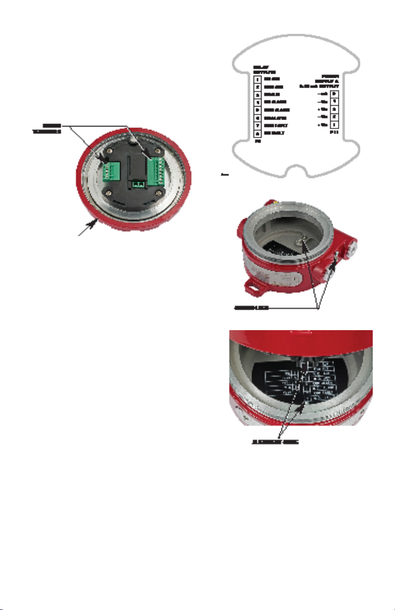
INSTALLATION
WARNING
All entries must contain appropriately rated
plugs or fittings. It is required that each
plug or fitting be wrench-tightened to an
appropriate installation torque and meet the
minimum thread engagement requirements
per the applicable local standards, codes,
and practices in order to retain the dened
ratings. PTFE sealant or equivalent should
be used on NPT threads.
NOTE
Detector housings must be electrically
connected to earth ground. Internal
and external earth ground terminals are
provided. For AEx (United States Zone)
installations the internal ground terminal
shall be used for the equipment grounding
connection. The external terminal can be
used for supplementary bonding where
local codes permit or require.
NOTE
The U5015 detector uses an internal
Intrinsically Safe (I.S.) Barrier. Proper NEC
I.S. grounding must be ensured.
GREASE/LUBRICATION
To ease installation and future removal, all
threaded covers, stopping plugs, and thread
adapters must be installed using thread lubricant.
The recommended lubricant is a silicone-free
grease, available from Det-Tronics.
For devices with NPT threads, Teflon tape or
thread seal lubricant must be used for enhanced
sealing capabilities.
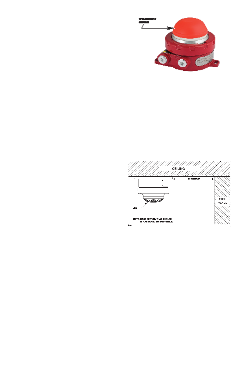
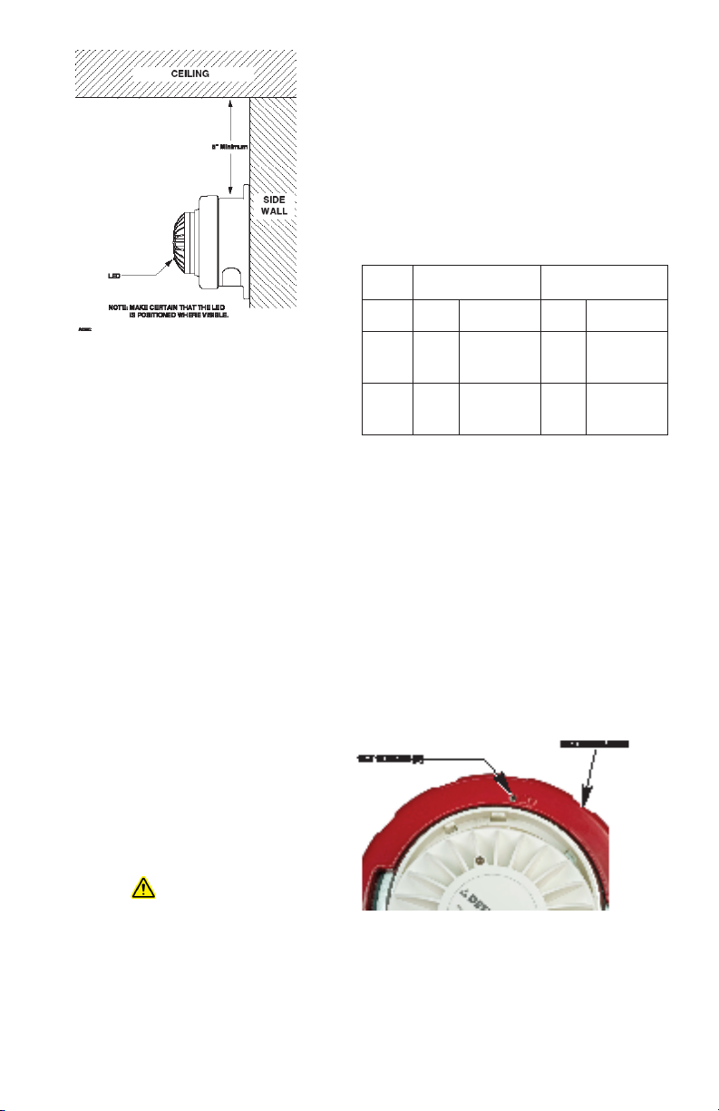
IDENTIFICATION OF DETECTOR MOUNTING
LOCATIONS
The most effective number and placement of
detectors varies depending on the conditions on
site. The individual designing the installation must
often rely on experience and sound judgment to
determine the detector quantity and best locations
to adequately protect the area. Note that it is
typically advantageous to locate detectors where
they are accessible for maintenance.
For additional information on detector location
and spacing, visit the National Fire Protection
Association's website (www.nfpa.org) and refer to
the National Fire Alarm and Signaling Code, NFPA
72, the standard on automatic fire detectors, or
your local codes and standards.

95-8723
6
3.5
PROTECTION AGAINST MOISTURE DAMAGE
It is important to take proper precautions during
installation to ensure that moisture will not come
in contact with the electrical connections of the
system. The integrity of the system regarding
moisture protection must be maintained for
proper operation and is the responsibility of the
installer.
If conduit is used, the use of proper conduit
installation techniques, breathers, glands, and
seals is required to prevent water ingress and/or
maintain the explosion-proof rating.
Conduit drains must be installed at water
collection points to automatically drain
accumulated moisture. Conduit breathers
should be installed at upper locations to
provide ventilation and allow water vapor to
escape. At least one breather should be used
with each drain.
Conduit raceways should be inclined so that
water will flow to low points for drainage and
will not collect inside enclosures or on conduit
seals. If this is not possible, install conduit drains
above the seals to prevent the collection of water
or install a drain loop below the detector with a
conduit drain at the lowest point of the loop.
POWER SUPPLY REQUIREMENTS
Calculate the total detection system power
consumption rate in watts from cold start-up.
Select a power supply with adequate capability
for the calculated load. Ensure that the selected
power supply provides sufficient regulated and
filtered output power for the entire system. If a
back-up power system is required, a float-type
battery charging system is recommended. If an
existing source of power is being used, verify
that system requirements are met.
TRANSPORT COVER
The Transport Cover (see Figure 4) keeps dust
and particles out of the smoke chamber that may
enter during transport, handling, or installation. It
should remain fastened on the detector through
the installation process.
IMPORTANT
Remove the cover only after installation
is complete and prior to powering the
detector for the rst time.
MOUNTING LOCATION OPTIONS
Ceiling Mount
The U5015 is intended for surface mounting. It is
normally mounted on the ceiling no less than six
inches from a side wall (See Figure 5). The exact
location of the detector must be determined by an
evaluation based on engineering judgement, or if
possible, by field tests.
Wall Mount
The U5015 can also be mounted on a side wall
(see Figure 6). The exact location of the detector
must be determined by an evaluation based
on supplemented engineering judgement, or if
possible, by field tests.
IMPORTANT
Whenever possible, select a mounting
orientation where the LED is visible to
personnel within the area.
MOUNT THE DETECTOR
Using three No. 8 flat head screws (or equivalent)
Figure4—U5015 Transport Cover
Figure5—U5015 Ceiling Mount

795-8723
3.5
placed through the counter bored holes in the
detector flange, secure the detector junction box
to the surface location.
WIRING CABLE REQUIREMENTS
Always use proper temperature rated cabling
type and diameter for input power as well as
output signal wiring. 14 to 18 AWG (.75 - 2.5 mm2)
shielded stranded copper wire is recommended.
The field wiring terminal connections are
certified for a single wire in size from 12-24 AWG
(0.2 to 2.5 mm2, or two conductors with same
cross section 0.2 to 0.75 mm2). The screws must
be tightened down with a torque 4.4 - 5.3 in-
lb (0.5 to 0.6 Nm). The metal housing must be
electrically connected to earth ground.
A minimum of 12 Vdc must be present at the
U5015 to ensure proper operation. The maximum
cable length from power source to U5015 is 2000
feet (610 m). When the U5015 Smoke Detector is
mounted remotely using an STB termination box,
maximum cable length from U5015 to STB is 500
feet (150 m).
WARNING
For eld connections, use wires/cables that
are rated at 20°C greater than the maximum
ambient temperature.
NOTE
In applications where the wiring is
installed in conduit, dedicated conduit is
recommended. Avoid low frequency, high
voltage, and non-signaling conductors to
prevent nuisance EMI problems.
JUMPER
Depending on the wiring option that is used,
jumpers may be required. See Table 3 for the
Jumper Usage Guide and Figures 12 to 15 for
wiring examples.
WIRING PROCEDURE
Ensure that all cables are terminated properly.
Conductor insulation should be stripped off with
a bare conductor length of 0.28 inch (7 mm)
maximum. Ensure that cable shield is properly
terminated and that bare shield wire is not allowed
to accidentally contact the metal housing or any
other wire.
Use the following instructions when wiring the
U5015 detector:
1. Slightly loosen the three setscrews located
on the retaining ring (see Figure 7).
Figure7—Setscrew Location
Figure6—U5015 Wall Mount
Table3—Jumper Usage Guide
Wiring
Option 0-20 mA Relay
1 Used No jumper
required Not
Used No jumper
required
2 Used No jumper
required Used
Jumper
required in
terminals 7 &
4 (P5)
3Not
Used
Jumper
required in
terminals 5 &
4 (P11)
Used
Jumper
required in
terminals 7 &
4 (P5)

95-8723
8
3.5
2. Unscrew the retaining ring to gain access
to the wiring terminals (see Figure 8), and
complete the installation of the system
conduit. Feed the external wiring through
the remaining junction box entry or M25
to 3/4 inch adapter. When installing the
junction box, use care not to damage the
wires and refrain from twisting them.
3. Connect the external wiring to the
appropriate terminals.
– Figure 9 shows the wiring terminals.
– Figure 10 shows the ground lug
locations.
– Figures 12 and 13 show wiring for single
detector configurations.
– Figures 14 and 15 show wiring for multiple
detector configurations.
4. Re-install the assembly. Use the alignment
guide (see Figure 11) to align the retaining
ring with the junction box.
5. Screw the retaining ring on to the junction
box and re-tighten the three setscrews.
Figure9—Wiring Terminals
Figure10—Ground Lug Locations
Figure11—Alignment Guide Location
Figure8—Location of Wiring Terminals

995-8723
3.5
MAINTENANCE
WARNING
To avoid a potential electrostatic discharge
(ESD), do not wipe or rub the surface of the
U5015 sensor module.
NOTE
The U5015 Smoke Detector contains no
user serviceable components and should
never be opened. The U5015 wiring
compartment is the only part of the smoke
detector that should be opened by the user
in the eld.
ROUTINE INSPECTION
Regularly scheduled maintenance is not
required, however, the U5015 cover and smoke
chamber should be inspected periodically when
detectors are located in abnormally dirty or dusty
environments, to ensure the smoke chamber is
not blocked by dirt or debris
The smoke detector can be tested using the
same methods employed for any photo-electric
detector. Det-Tronics recommends using a
test aerosol smoke dispenser for periodic
maintenance of the detector.

95-8723
10
3.5
Figure12—Single Detector Wiring (0-20 mA used, Relays not used)
Figure13—Single Detector Wiring (0-20 mA not used, Relays used)

11 95-8723
3.5
Figure14—Multiple Detector Wiring (0-20 mA used, Relays not used)

95-8723
12
3.5
Figure15—Multiple Detector Wiring (0-20 mA not used, Relays used)

13 95-8723
3.5
U5015 MODEL MATRIX
MODEL DESCRIPTION
U5015 Explosion Proof Smoke Detector
TYPE MATERIAL
AAluminum (AL)
TYPE # OF PORTS
11 Port
22 Port
33 Port
44 Port
TYPE THREAD TYPE
N3/4" NPT
MM25
TYPE OUTPUTS
12 0-20 mA, Relay, Non-Latching
13 0-20 mA, Relay, Latching
TYPE APPROVAL
AFM/IECEx/CSA
CCSA
FFM/IECEx
RVNIIFTRI (Russia)
DEVICE REPAIR AND RETURN
The sensor module is field replaceable in case of
dirtiness, damage or failures incurred in the field.
The detector is not field repairable. If it has been
determined that the product is faulty, then the
device should be returned to the factory for repair.
Details of the Det-Tronics Return Material
authorization (RMA) process are available at
www.det-tronics.com/technicalsupport/Pages/
default.aspx
If it is determined that your material should be
returned, Det-Tronics Technical Support will
ask you to complete an RMA form (online or
downloadable). After receipt of this form, the
team will issue you a unique RMA number.
Include a copy of your RMA form inside the
packaging. Please make certain to display
the RMA number clearly on the outside of your
packaging. Shipments received without this RMA
number displayed will be refused.
Pack the unit properly, always using sufficient
packing material. Wherever possible, return the
product using the original Det-Tronics packing
materials. Where applicable, use an antistatic
bag as protection from electrostatic discharge.
NOTE
Det-Tronics reserves the right to apply a
service charge for repairing returned
product damaged as a result of improper
packaging.
Return all equipment via transportation prepaid to
the factory in Minneapolis.
ORDERING INFORMATION
When ordering, please specify:
U5015 Explosion Proof Smoke Detector
Refer to the U5015 Model Matrix for details.
SPARE PARTS
U5015 Replacement Sensor Module
104286-001
ACCESSORIES
Detector Tester (Canned Smoke) 000119-008
Canned Smoke (Spare) 000119-046
Grease (silicone-free) 005003-001
Magnet
102740-002
Magnet with Extension Pole
007739-001
Stop Plug, 3/4" NPT, AL
101197-001
Stop Plug, M25, AL
101197-005
Q5016-1 Duct Mount w/ 1 ft. tube 013901-001
Q5016-3 Duct Mount w/ 3 ft. tube 013901-003
Q5016-6 Duct Mount w/ 6 ft. tube 013901-006
Q5016-10 Duct Mt. w/ 10 ft. tube 013901-010

95-8723
14
3.5
APPENDIX A
FM APPROVAL DESCRIPTION
Applcable Documents:
FM 3810: 2005 Elec. and Electronic Test, Measuring, and Process Control Equipment
FM 3600: 2011 Electrical Equipment for use in Hazardous (Classified) Locations
FM 3610: 2010 Intrinsically Safe, Class I, II, III, Div I, Haz. Loc.
FM 3611: 2004 Elec. Equip. for use in Cl. I/II, Div. 2 and Cl. III, Div. 1/2 Haz. Loc.
FM 3615: 2006 Explosion proof Electrical Equipment
FM 3230: 2010 Smoke actuated detectors for automatic alarm signaling
ANSI/ISA 1010-1: 2004 Safety Requirements for Electrical Equipment for Measurement,
Control, and Laboratory Use – Part 1: General Requirements
ANSI/IEC 60529: 2004 Degrees of Protection Provided by Enclosures (IP Code)
ANSI/ISA 60079-0: 2013 Explosive atmospheres – Part 0: Equipment – General Requirements
ANSI/ISA 60079-1: 2013 Explosive atmospheres – Part 1: Equipment protection by Flameproof
Enclosures “d”
ANSI/ISA 60079-11: 2014 Explosive atmospheres – Part 11: Equipment protection by intrinsic
safety “i"
Special Conditions For Safe Use X:
1. The U5015 is to be installed in locations where the risk of mechanical damage is low.
2. Potential electrostatic charging hazard please see instructions for proper installation.
3. All unused device openings must be closed using a suitably certified plug.
4. For field connections, use wire rated 20°C greater than maximum ambient temperature.
5. For AEx d rated Model U5015 Smoke Detector, the flameproof joints are not allowed to be
repaired per manufacturer's instruction manual.
6. The U5015 shall be used with the Q5016 Duct Mount Accessory for duct mount installations.
U5015
Class 1 Div 1 Groups B, C, D T4
Class 1 Div 2 Groups A, B, C, D T4
Class 1 Zone 1 AEX db ia IIC T4 Gb
Tamb –20°C to +65°C
IP44
Q5016 Duct Amount Accessory
ANSI/UL 268A: 4th Edition Standard for Smoke Detectors for Duct Applications (only when
installed on the vertical surface of the duct)

15 95-8723
3.5
APPENDIX B
CSA APPROVAL DESCRIPTION
U5015
Class - C481804 - Signal Appliances - Systems - For Hazardous Locations
Ex db ia IIC T4 IP44
Applicable Requirements
C22.2 No. 0-M91 General requirements - Canadian Electrical Code, Part II
C22.2 No. 60529: 2015 Degrees of protection provided by enclosures (IP Code).
C22.2 No. 610101-1: 2012 Safety requirements for electrical equipment for measurement, control,
and laboratory use - Part 1: General Requirements.
C22.2 No. 60079-0: 2015 Electrical apparatus for explosive gas atmospheres - Part 0: General
Requirements
C22.2 No. 60079-1: 2016 Explosive atmospheres - Part 1: Equipment protection by flameproof
enclosures "d".
C22.2 No. 60079-11: 2014 Electrical apparatus for explosive gas atmospheres - Part 11: Intrinsic
Safety "i".
Special Conditions For Safe Use X:
1. Field wiring must be in accordance with CEC Part 1, Section 18.
2. The enclosure must be bonded to ground according to CEC Part 1, Section 18.
3. For enclosures with metric conduit entries certified metric to NPT adaptors shall be used.
4. All unused openings must be closed using suitably certified plugs.
5. A seal shall be installed within 18" of enclosure.
6. Measures must be taken to avoid ignition due to mechanical impact.
7. IPx4 maintained only when mounted on a ceiling.

95-8723
16
3.5
APPENDIX C
IECEx APPROVAL DESCRIPTION
U5015
IECEx FMG15.0014X
Ex db ia IIC T4 Gb
Tamb –20°C to +65°C
IP44
IEC Standards:
IEC 60079-0: 2011 Electrical apparatus for explosive atmospheres, General Requirements
IEC 60079-1: 2014 Electrical apparatus for explosive atmospheres, Flameproof enclosure "d"
IEC 60079-11: 2011 Intrinsic Safety explosive atmospheres Equip protection by Intrinsic Safety
Special Conditions For Safe Use X:
1. The U5015 is to be installed in locations where the risk of mechanical damage is low.
2. Potential electrostatic charging hazard please see instructions for proper installation.
3. All unused device openings must be closed using a suitably certified plug.
4. For field connections, use wire rated 20°C greater than maximum ambient temperature.
5. For AEx d rated Model U5015 Smoke Detector, the flameproof joints are not allowed to be
repaired per manufacturer's instruction manual.

17 95-8723
3.5
APPENDIX D
ADDITIONAL APPROVALS
RUSSIA & KAZAKHSTAN
VNIIFTRI
CERTIFICATE OF CONFORMITY TO TP TC 012/2011
No. TC RU C-US. BH02.B.00239
1Exd[ia]IICT4 IP44
T4 (Tamb = –20°C to +65°C)
Declaration of Conformity to TP TC 020/2011 (EMC)
EAЭC No. RU д-US.PA01.B.50006
RUSSIA
VNIIPO
CERTIFICATE OF CONFORMITY TO TECHNICAL REGULATIONS, GOST R 53325-2012
C-US.цC13.B.00192

X3301 Multispectrum
IR Flame Detector
PointWatch Eclipse®IR
Combustible Gas Detector
FlexVu®Universal Display
with GT3000 Toxic Gas Detector
Eagle Quantum Premier®
Safety System
FlexSonic®Acoustic
Leak Detector
95-8723
Corporate Office
6901 West 110th Street
Minneapolis, MN 55438 USA
www.det-tronics.com
Specications subject to change without notice.
All trademarks are the property of their respective owners.
© 2020 Detector Electronics Corporation. All rights reserved.
Det-Tronics manufacturing system is certied to ISO 9001—
the world’s most recognized quality management standard.
Phone: 952.941.5665
Toll-free: 800.765.3473
Fax: 952.829.8750
det-tronics@carrier.com
Table of contents
Other Det-Tronics Smoke Alarm manuals
Popular Smoke Alarm manuals by other brands

Elkron
Elkron SD610 Installation, programming and functions manual

QOLSYS
QOLSYS IQSmoke installation guide

System Sensor
System Sensor D2-AUS Installation and maintenance instructions

Distech Controls
Distech Controls GS-SDD Series Hardware installation guide

First Alert
First Alert SA520 user manual

Convoy Security
Convoy Security YT202 Installation and maintenance instructions