Nu-Calgon iWave-R User manual

Nu-Calgon Installation Instructions 4-430
iWave®-R
Residential Air Cleaner
Mounting Options
Fan Inlet Mount
• Internal magnets holding unit to fan inlet (shaft side).
• Use self-tapping screws to secure device, especially for high velocity applications or excessive vibration when using magnets.
Inside Wall/Cabinet Mount
• Internal magnets holding unit to wall duct or air handler metal panel.
External Duct Mount
• Cut/drill a 3 inch hole in duct to install and use two self-tapping screws to hold unit to duct.
IMPORTANT!
Install in return air between air filter and cooling coil. For external duct mount, make sure sheet metal sits against gasket surface; the high voltage emitter ends (fiber brushes)
must be 2 inches away from other metal and other wiring to prevent grounding/premature failure.
Installation Instructions
1. Disconnect air handler power before installing.
2. Mount the iWave-R after the particle filter and before the indoor coil. This ensures pathogens (i.e., mold) and odors are controlled
throughout the entire depth of the coil in addition to the breathing space.
3. The iWave-R is designed with universal mounting- either attach with screws or affix to the system with integral magnets.
Mount near the fan inlet (shaft side) on a metal surface in the air handler, internal wall duct or external wall duct depending on
what is best for the installation. For external duct mount, a three inch diameter hole will need to be cut/drilled out of the duct.
IMPORTANT: If mounting on the fan housing, ensure the iWave-R is secured from fan vibration - use short length self-tapping
screws so as not to impair operation of fan.
CRITICAL: The iWave-R is designed for flush, external duct mount installations as an optional install. Ensure in all installations
that other metal surfaces/wires are kept a minimum of two inches away from the tip ends of the high voltage emitters to prevent
grounding, leading to premature failure.
4. The iWave-R has universal voltage capability, connect 24VAC to 240VAC voltage input, whatever is most convenient for quick
installation. Although the device only pulls 10 watts, sometimes a dedicated 24VAC power supply may be necessary depending on
the current load on the transformer for other system accessories.
5. Unit may be powered 24/7 or may be interlocked with indoor fan – unit only purifies when air is flowing. If unit is wired with the fan, the
quickest air purification to address an air concern is to let the fan/iWave-R run continually for 72 hours. Leaving the fan continually
in the ‘on’ position will provide the best ongoing air purification in the house.
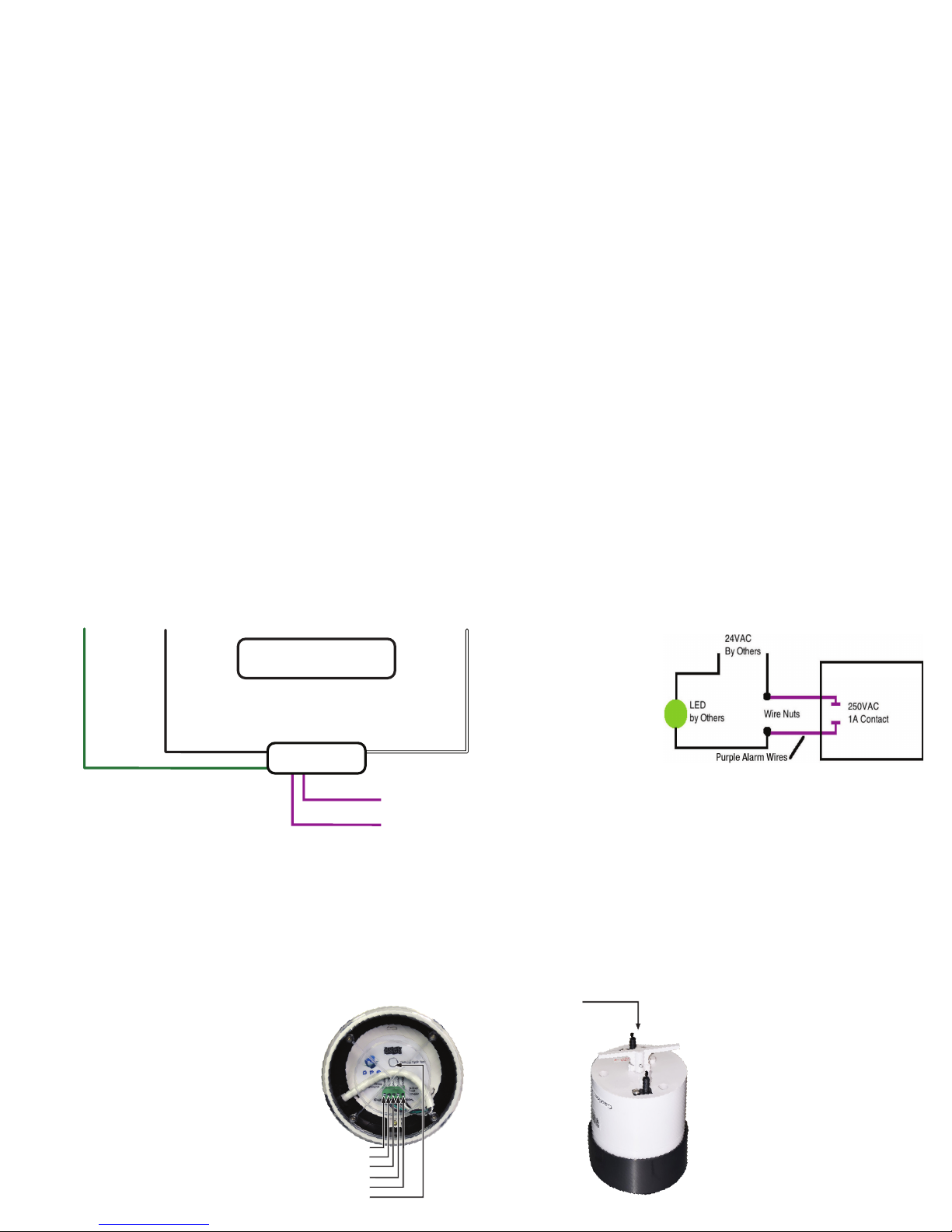
6. Wiring: The iWave-R has a patent-pending universal voltage 24VAC to 240VAC input capability. The black wire (marked ‘AC’ on
label) is for 24VAC to 240VAC voltage input. The white wire (marked ‘N’ on the label) is the neutral leg for 24VAC or 120VAC; or the
other hot leg for 208/240VAC. The green striped wire is ground, marked ‘G’ on the label. The brown wires (marked ‘A’ on the label)
are leads to a normally closed alarm contact – see step 7.
7. The iWave-R is equipped with an alarm contact option to provide a visual indicator outside of the air conditioning system to let
the homeowner know that it is in normal operation or if there is a fault. The alarm contact, a normally closed contact, rated at 240
VAC/1A, will require a power source and visual indicator, such as a LED. In normal mode, the LED will stay illuminated. If the device
goes into default mode, the LED will not light. If a homeowner wants a remote indication of iWave-R status, it is recommend that the
24VAC light (bought separately) be powered through the alarm contacts and sent to a remote wall.
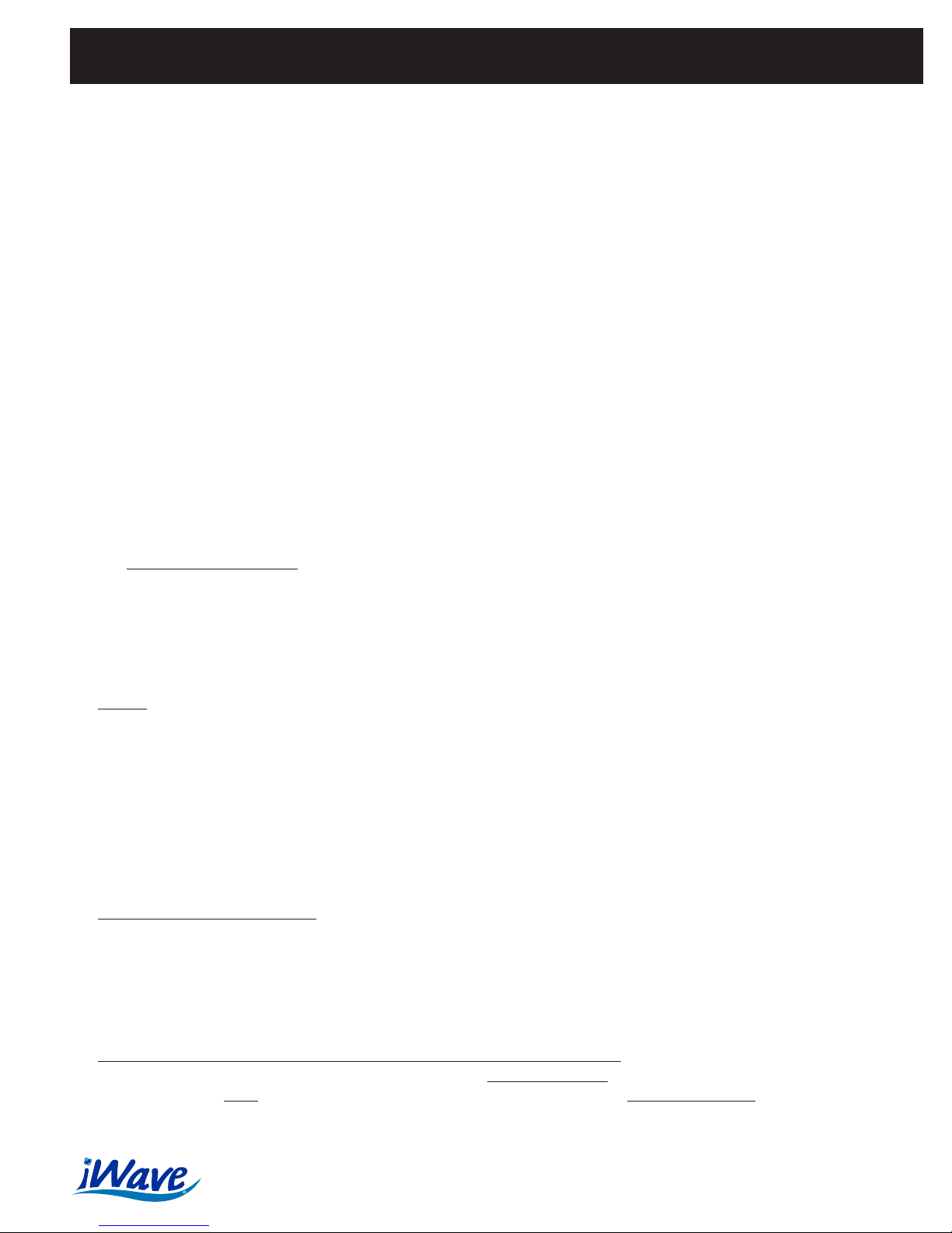
8. When powered up, a green LED on the iWave-R will illuminate; the ionizer is working and the stepper motor for the cleaning feature
is in the home position. If the light is not illuminated, check voltage to the iWave-R. If there is power, the unit has a 240VAC/1A in-line
fuse, check the fuse.
9. Self-Cleaning/Program Feature: The patent-pending iWave-R has a self-cleaning feature to ensure it is always operating at peak
performance over its design life. The functions for the button include:
a. While in normal operation mode, press the button once, the LED light will flash and the stepper motor starts an on-demand
cleaning cycle.
b. While in cleaning cycle (after step ‘a’ above), press the button and hold for 3 seconds, it goes into the mode of setting the
cleaning cycle intervals. The iWave-R is designed to be programmed for 1, 3, 5, or 10 day cleaning cycle intervals. The iWave-R
is factory preset for cleaning the emitters every third day; this is adequate for most applications and will not need to be
reprogrammed in the field.
While in the cleaning mode (with LED flashing and cleaning feature working):
a. Press the button and hold for 3 seconds, the LED will flash once every second and the motor works once every day.
b. Press the button twice (the first press hold for three seconds), the LED will flash twice every second and the motor works once
every 3 days. This is the factory preset program.
2611 Schuetz Rd. • St. Louis, MO 63043 • 800-554-5499 • www.nucalgon.com • Calgon is a licensed trade name • (1118) 4-430

c. Press the button three times (the first press hold for three seconds), the LED will flash five times every second and the motor works
once every 5 days.
d. Press the button four times (the first press hold for three seconds), the LED will flash ten times every second and the motor works
once every 10 days.
The iWave-R remembers the programmed cleaning cycle days. After the power source is removed and applied again,
the iWave-R will automatically operate and go back to the previous days.
Note: The iWave-R is designed to be a long term IAQ investment, not requiring ongoing maintenance of replacing
expensive parts every year or two like other market approaches. The ion emitters (fiber brushes) used in the iWave-R are
designed to where they could easily be replaced after many years in service; in the unlikely event they ever needed to
be replaced. Replacement requires a Phillips screwdriver and a few minutes; contact Nu-Calgon for further questions.
The iWave-R remembers the programmed cleaning cycle days. After the power source is removed and applied again, the iWave-R
will automatically operate and go back to the previous days.
Note: The iWave-R is designed to be a long term IAQ investment, not requiring ongoing maintenance of replacing expensive parts
every year or two like other market approaches. The ion emitters (fiber brushes) used in the iWave-R are designed to where they
could easily be replaced after many years in service; in the unlikely event they ever needed to be replaced. Replacement requires a
Phillips screwdriver and a few minutes; contact Nu-Calgon for further questions.
24, 110/120, 208/240
VAC Power
iWave-R
BLACK WIRE
(Hot)
GREEN WIRE
(Ground)
ALARM LEADS
(See Diagram)
V
oltage Input Neutral or Hot (208/240)
WHITE WIRE
(*Neutral OR Hot)
NOTE: For best results, power
continually or cycle with the fan. *Neutral WHITE wire becomes
a HOT wire if using 208/240.
Remote mounted LED will illuminate when the iWave-R is powered
and there are no faults. All remote mount wiring, LED, wire nuts
and voltage source are provided, mounted and wired by others.
Air Flow Direction
CRITICAL: Make
sure air flows
across both
brushes at the
same time, like a
football through a
field goal post.
Installation Instructions Continued
iWave®-V
Vortex Air Cleaner
Mounting Options
Installation Instructions
1. Disconnect air handler power before installing.
2. Mount unit in one of three ways as shown on the previous page—duct, internal wall or fan inlet.
3. Connect only 24 VAC nominal power—a dedicated power supply may be necessary on some residential systems to prevent
excessive power draw on the control board. Check with AHU manufacturer if 10VA capacity is available—WHEN IN DOUBT USE
A DEDICATED CIRCUIT!
4. Unit may be powered 24/7 or may be interlocked with fan—unit only delivers plasma and purifies when air is flowing.
5. Red wire goes to 24 VAC, black wire goes to neutral or ground.
6. Green LED will illuminate when powered and there are no faults.
7. Do not touch carbon fiber brushes while powered!
IMPORTANT! Ensure air flows across both brushes at the same time like a football through a field goal post.
8. CRITICAL! Ensure all 24 VAC wiring stays away from carbon fiber brushes and is per NEC / local codes. Secure wires if necessary
with wire/tape so they never move and touch brushes.
9. CRITICAL! Ensure the carbon fiber brushes are at least 2 inches away from anything metal and other wiring!
10. Mount the device after final particle filtration in the system. The best location to mount the device is after the particle filter and
before the cooling coil; if this is not possible, after both the particle filter and cooling coil is acceptable on the supply. Mounting the
device before the coil will ensure pathogens, mold and odors are controlled throughout the entire depth of the coil.
Fan Inlet Mount
• Internal magnets holding
unit to fan inlet (shaft side).
• Use self-tapping screws
to secure device,
especially for high velocity
applications or excessive
vibration when using
magnets.
Inside Wall/Cabinet
Mount
• Internal magnets
holding unit to wall
duct or air handler
metal panel.
External Duct Mount
• Use two self-tapping
screws to hold unit
to duct.
• Drill two 3/8" holes
spaced 1-3/4" apart
on center or drill one
2-1/4" hole.

11. Leaving the fan in the “On” position will provide the best air purification results. If the fan cycles based on comfort cooling/heating
setpoints, the air quality will not be the best possible.
12. Unit has a 250 VAC/1A in-line fuse—if 24 VAC is confirmed and LED is off, check fuse.
24 VAC Power
iWave-V
RED WIRE
(Hot)
V
oltage Input Neutral
BLACK WIRE
(Neutral)
NOTE: For best results, power
continually. From time-to-time,
lint/dust must be brushed off the
iWave-V emitters with a soft
bristle brush. Turn off system first.
Maintenance:
1. Turn power off.
2. Wipe off the carbon fiber brushes as needed to keep
the ion output at maximum levels. Use a cloth or nylon
brush to gently clean the brushes when the power is off.
3. Brush cleaning intervals will depend on filtration
effectiveness upstream of the device and may range
from requiring cleaning every filter change to once per
year. It is highly recommended to review the brush
cleanliness while changing filters.
4. There are no parts to replace. Enjoy your new air
cleaning system!
iWave®-F & iWave®-M
Flexible Air Cleaner & Mini Flexible Air Cleaner
Installation Instructions:
The iWave-M is a highly versatile ion generating device that is designed to be typically installed at the base of the cooling coil for
ductless and duct air conditioning systems; but the device can be installed in supply air as well. The iWave-M is an ideal, no replacement
part device that can be integrated into wall or ceiling cassette indoor coils of mini-splits, PTAC units or commercial systems where there
may not be enough room to install the iWave-C between the filter and coil. It can also be used to inhibit mold in ice machine applications.
The 18 inch ion generating bar can be used for coils up to 36 inches wide. For coils beyond the 18 inch ionizer length, simply center
the ionizer bar on the coil to make sure the ionization best covers the coil width. For coils shorter than 18 inches, see the section on
iWave-M modification directions on the back page.
Simply peel back the sticky backing to the power pack and ionization bar and stick it across the width of the coil, near its base so the
iWave-M treats the coil as well as the breathing zone. For ice machines, install on top and/or side panel of equipment, above the water
line so it creates a plasmafield inside the machine. Connect the appropriate leads of the iWave-M to 110VAC to 240VAC power (see
diagram on back page) and reassemble the equipment and turn on power to the unit.
Mini-Split Instructions:
1. Turn power off to mini-split.
2. Open front cover of indoor unit.
3. Remove filter screens.
4. Measure the length of coil and affix ionizer bar to solid surface (often plastic) on top of the coil. If there is no plastic surface, the
iWave-M can be affixed directly to the top of the fins. (See Figure 6.) The width of the plastic region will easily accommodate the
iWave-M ionizer bar so it can treat the coil, barrel blower and breathing zone of the room. For coils between 24-36 inches, center
the ionizer bar on top of the coil and affix. For coils less than 18 inches, refer to the iWave-M modification directions below. Note:
Securing the iWave-M with adhesive backed Velcro®strips is another option for easier ongoing removal for other servicing within
system.
Critical: Keep any metal from directly touching the emitters.
5. Depending on mini-split model, the area available to mount power pack will vary. Either affix with adhesive backing to back cabinet
wall or side of coil. (See Figure 6.)
6. Run wires to the electrical compartment to hook up to 110VAC to 240VAC incoming power source to where iWave-M will power on
continually. For 110/120VAC input, connect the black wire (hot) and white wire (neutral). For 208/240VAC input, connect red wire
(hot) and white wire (Neutral or Other AC Phase) to applicable electrical terminal block. Do not use the black wire with 208-240VAC
input! Important: Always add a wire nut to wire not being used (red or black) depending on voltage input.
7. Trim wires to length hook up to appropriate terminal connections and connect. Harness/secure wires within the equipment as
necessary. The LED on iWave-M power pack will turn green when power is supplied.
8. Reassemble filter screens, close the front cover and turn on power to mini-split.
iWave-M Modification Instructions:
For typical minisplit (or ice machine) applications, no adjustment in iWave-M length is necessary. For an irregular application
where the iWave-M is too long for the coil which it’s being applied, perform the following steps:

2611 Schuetz Rd. • St. Louis, MO 63043 • 800-554-5499 • www.nucalgon.com • Calgon is a licensed trade name • (1118) 4-430
1. Measure how much past the end of the coil the iWave-M lies.
2. Bend the iWave-M back on top of itself (DO NOT bend under with sticky backing facing each other) so the brush pairs
on the top will lay next to the brush pairs on the bottom, shown in Figure 1.
3. Peel the backing off of the iWave-M and press it down to the cooling coil starting at the power entry side of the
iWave-M. DO NOT press down on the end of the iWave-M that will need folded to shorten the length, see Figure 2.
Note: Securing the ionization bar with an adhesive backed Velcro® strips is another option for easier removal with
equipment service.
4. Fold the iWave-M back to achieve the length required, lining up the bottom and top layer brush pairs as shown in Figure
1, and place a piece of electrical tape across the joint. See Figure 3.
5. Continue to use electrical tape down the iWave-M towards the end, making sure that the tape joints are between the
brush pairs. DO NOT allow the tape to cover the brush pairs. See Figure 4.
6. DO NOT crease the end of the iWave-M flat. As a guide, use a #2 Phillips screwdriver inside the fold joint to ensure the
proper bend is achieved. See Figure 5.
7. Once the iWave-M has been folded and taped to the length required, push it down on the coil.
8. A successful fold procedure will create “pockets” for the carbon fiber brushes to emit the ions.
Figure 1 Figure 2 Figure 3 Figure 4 Figure 5
110/240 VAC Power
iWave-F
BLACK WIRE (HOT)
V
oltage Input
WHITE WIRE
Neutral-110/120 VAC
Hot -208/240 VAC
110/240 VAC Power
iWave-M
BLACK WIRE (HOT)
V
oltage Input
WHITE WIRE
Neutral-110/120 VAC
Hot -208/240 VAC
iWave-F Modification Instructions:
When the iWave-F is too long for the coil which it’s being
applied, perform the following steps:
1. Measure how much past the end of the coil the iWave-F
lies.
2. Bend the iWave-F back on top of itself (DO NOT bend
under with sticky backing facing each other) so the
brush pairs on the top will lay next to the brush pairs on
the bottom, shown in Figure 1.
3. Peel the backing off of the iWave-F and press it down
to the cooling coil starting at the power entry side of
the iWave-F. DO NOT press down on the end of the
iWave-F that will need folded to shorten the length. See
Figure 2.
4. Fold the iWave-F back to achieve the length required,
lining up the bottom and top layer brush pairs as shown
in Figure 1, and place a piece of electrical tape across
the joint. See Figure 3.
5. Continue to use electrical tape down the iWave-F
towards the end, making sure that the tape joints are
between the brush pairs. DO NOT allow the tape to
cover the brush pairs. See Figure 4.
6. DO NOT crease the end of the iWave-F flat. As a guide,
use a #2 Phillips screwdriver inside the fold joint to
ensure the proper bend is achieved. See Figure 5.
7. Once the iWave-F has been folded and taped to the
length required, push it down on the coil.
8. A successful fold procedure will create “pockets” for
the carbon fiber brushes to emit the ions.
Cleaning: If required, use a wet wipe or damp cloth to
clean the ionizer bar. A soft bristle brush, like toothbrush,
can also be used to clean debris from ion emitters. Do
not expose the iWave-F to corrosive cleaners. Contact
Nu-Calgon for further guidance with coil cleaner options.
Typical Location Install on Ductless Wall System:
Affix iWave-F to the top of coil on plastic strip (or top of fins)
to treat coil, blower and living space.
Affix iWave-F power pack to back of cabinet.Figure 6

WARNING
1. The health aspects associated with the use of this product and its ability to aid in disinfection of environmental air have
not been investigated by UL LLC.
2. This product shall not be installed behind a suspended floor/ceiling or a structural wall, ceiling, or floor.
3. This product is suitable for mounting to duct of metallic Construction only. Installation must be such that the structural
integrity of the ducting is not compromised.
4. RISK OF ELECTRIC SHOCK. CAN CAUSE INJURY OR DEATH: DISCONNECT All ELECTRIC POWER SUPPLIES
BEFORE SERVICING
Three-Year Limited Warranty:
The iWave-C offers a limited warranty for three years that covers any defects in material or workmanship under normal use. If you make a claim
during the warranty period, you must provide proof of purchase and proof of proper installation by a licensed contractor for the warranty to be valid.
The iWave warranty does not cover labor, return shipping charges, damage from improper installation or improper voltage usage. The iWave warranty
begins on the date that the unit was purchased. Installation of your iWave by any person other than a licensed contractor will void the warranty.
Contact your local Nu-Calgon account manager or info@nucalgon.com with further questions.
Problem Solution
Unit won’t power up Confirm proper voltage is applied and to the correct terminal
Display shows “FALT” Remove power, wait one minute and reapply power. If “FALT” still appears, try using alternate power
source, i.e. low voltage input versus high voltage input or vice versa. If FALT still shows, call Nu-Calgon.
No Display / LED If the correct voltage source has been confirmed and the unit does not power up contact Nu-Calgon.
Troubleshooting:

iWave®-C
Commercial Air Cleaner
Installation Instructions:
The iWave-C is designed for metal duct mounting applications. The preferred mounting location is after a prefilter and
before the cooling coil. An alternate mounting location is the supply air duct or the return air duct. The weatherproof housing
will allow mounting indoor or outdoor.
Step 1. Turn power off to the unit.
Step 2. After finding the appropriate location, cut or drill a 4 inch (100mm) round hole. Insert the unit into the 4 inch (100mm)
round hole and secure with four self tapping screws provided. Please note, if the unit is being mounted to duct board, the
included spring loaded wing nuts and bolts will be required.
Wiring:
Confirm power is off prior to wiring. Follow all local and national electric, mechanical and building codes when in-stalling and wiring.
The iWave-C can be powered with a 24VAC low voltage circuit or 110VAC to 240VAC high voltage circuit. The face panel of the unit is
labeled showing which terminals are 24VAC, 110-240VAC input and neutral and come prewired from the factory. Opening the unit is not
necessary for installation. The unit is provided with 6 feet of liquid-tight flex conduit to reach a junction box for wiring.
The wires are color coded as follows:
• Black wire = 24-240VAC input
• White wire = Neutral
• Green wire = Ground
• Purple wires = Alarm Dry Contact
The unit is provided with alarm contacts for use with a building management system. When the unit is powered and there are no faults,
the alarm “dry” contacts will be closed, providing continuity. The contacts are rated up to 250VAC at 1A.
CAUTION! NEVER TOUCH BRUSHES WHILE OPERATING. SHOCK MAY OCCUR. DO NOT CONNECT WITH AN
EXTENSION CORD.
Maintenance:
PURPLE WIRE
PURPLE WIRE
24, 110/120, 208/240
VAC Power
iWave-C
BLACK WIRE
(HOT)
GREEN WIRE
(Ground)
Voltage Input
(24 to 240VAC)
Neutral
WHITE WIRE
(Neutral)
NOTE: For best results, power continually
or cycle with the fan.
(Optional Alarm Dry Contacts. See other diagram)
Ground
Remote mounted LED will
illuminate when the iWave-C
is powered and there are
no faults. All remote mount
wiring, LED, wire nuts and
voltage source are provided,
mounted and wired by
others.
ALARM RELAY WIRING EXAMPLE
iWave-C
The iWave-C is designed to be maintenance free for years of trouble-free operation with the patent pending self-cleaning
system; eliminating the need to replace expensive UV lights/cells every couple of years as with competing technologies.
Although extensively tested for durability, it’s possible over years of self-cleaning cycles, the carbon fiber brushes can wear
from friction and require replacement. With the unit powered off, remove the iWave-C from the duct. Remove the two Phillips
screws that fasten the brushes to the iWave-C. Pull the brushes out of the electrical connector and insert new brushes
(available through Nu-Calgon). Replace the Phillips screws and attach the iWave-C into the duct and re-energize the device
to initiate normal operation.
Self Cleaning Button
Neutral
24-240VAC Input
Alarm
Alarm
Ground
Self Cleaning Wiper
(shown in ‘home’ position)
Table of contents
Other Nu-Calgon Air Cleaner manuals