5
For more information visit www.nu-heat.co.uk
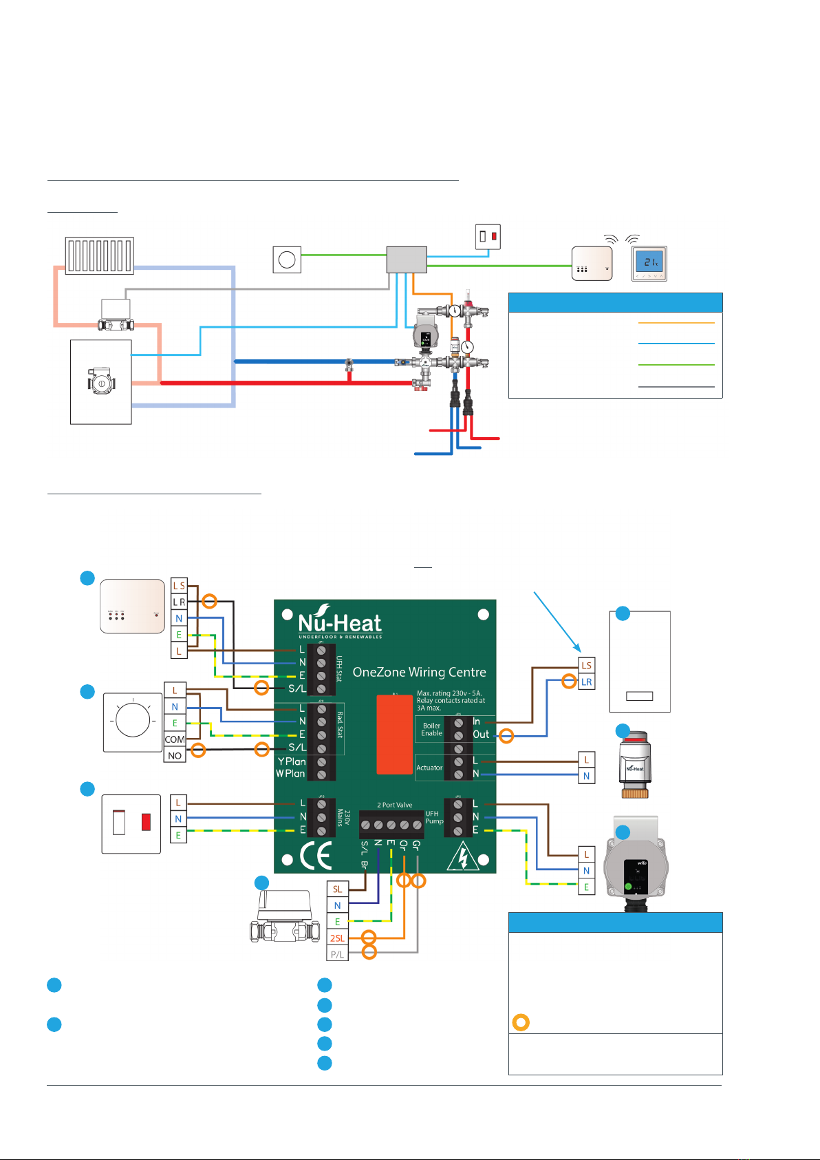
Electrical components
neoAir wireless thermostat
NeoAir is a wireless, battery powered
programmable thermostat that is
capable of upgrade to smart control
(see neoHub below). The room/zone is
individually programmed for
temperature and times of use. This can
be independent control or in
conjunction with an existing radiator
system. For screed and floating floor
systems, allowance should be made for
the longer warm-up time of underfloor
heating. With LoPro®Max systems
response time is similar to that of a
traditional radiator system.
In order to comply with wiring
regulations bathroom zones must have
the thermostat fitted outside the room,
i.e. next to the door at light-switch
height.
RF Switch
This is the wireless base receiver, to be
fitted near to the OneZone®wiring
centre.
OneZone®wiring centre
The wiring centre can either be fitted
beside or remotely from the heating
components. It can be wired to suit
individual system requirements.
neoHub
The neoHub connects to a home
broadband router and wirelessly to
the neoAirs in a home. Simply plug into
a router, connect to your Nu-Heat
neoApp on an Android or iOS device
and take control of the underfloor
heating from anywhere.
neoPlug
neoPlug is a simple smart plug that
(with neoHub) enables on/o control
of a household appliance. It also acts as
a signal booster between the neoAir
and the RF Switch.
OPTIONAL COMPONENTS