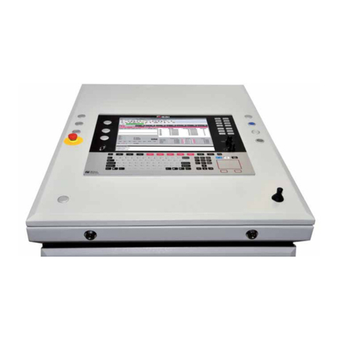
IDEATEC DLC4000 User manual

IDEATEC S.A. - Z.I. de Noville-les-Bois - rue Léopold Génicot 19A - 5380 Fernelmont, Belgium - Tel: +32(0)81 42 00 10 - Fax: +32(0)81 57 91 70 - E-mail: [email protected]
User’s guide DLC4000/DLC8000 - Doc. V2.1 - Firmware V3.1 Page 1
&
REF.P0050F0012
REF.P0050F0013
Due to technological advances, the manufacturer reserves the right to modify
the characteristics of this product without notice
USER’S GUIDE
Control Systems 4+2 or 8+2 outputs - 3 inputs

IDEATEC S.A. - Z.I. de Noville-les-Bois - rue Léopold Génicot 19A - 5380 Fernelmont, Belgium - Tel: +32(0)81 42 00 10 - Fax: +32(0)81 57 91 70 - E-mail: [email protected]
User’s guide DLC4000/DLC8000 - Doc. V2.1 - Firmware V3.1
1.
2.
Page 2
0.34
22
X
X
X
X
X
X
X
X
X
X
X
X
X
X
X
X X X
0.5
20
X
X
X
X
X
X
X
X
X
X
X
X
X
X
X
X X X
0.75
18
X
X
X
X
X
X
X
X
X
X
X
X
X
X
X
X X X
1.5
16
X
X
X
X
X
X
X
X
X
X
X
X
X
X
X
X X X
2.5
14
1.2m
4 Feet
1m
3.5 Feet
0.9m
3 Feet
0.9m
3 Feet
0.9m
3 Feet
X
X
X
X
X
X X X
4
12
1.8m
6 Feet
1.7m
5.5 Feet
1.5m
5 Feet
1.5m
5 Feet
1.3m
4.5 Feet
1.2m
4 Feet
1.2m
4 Feet
1m
3.5 Feet 1m 3.5 Feet
6
10
3.0m
10 Feet
2.7m
9 Feet
2.4m
8 Feet
2.2m
7.5 Feet
2.1m
7 Feet
2m
6.5 Feet
1.8m
6 Feet
1.8m
6 Feet 1.6m 5.5 Feet
10
8
4.7m
15.5 Feet
4.2m
14 Feet
4m
13 Feet
3.6m
12 Feet
3.3m
11 Feet
3.2m
10.5 Feet
3m
10 Feet
2.7m
9 Feet 2.5m 8.5 Feet
16
6
7.6m
25 Feet
6.8m
22.5 Feet
6.2m
20.5 Feet
5.8m
19 Feet
5.3m
17.5 Feet
5m
16.5 Feet
4.7m
15.5 Feet
4.4m
14.5 Feet 4.2m 14 Feet
25
4
12m
39.5 Feet
11m
36 Feet
10m
33 Feet
9.2m
30.5 Feet
8.5m
28 Feet
8m
26.5 Feet
7.4m
24.5 Feet
7m
23 Feet 6.7m 22 Feet
35
2
19.2m
63 Feet
17.3m
57 Feet
16m
52.5 Feet
14.7m
48.5 Feet
13.7m
45 Feet
12.8m
42 Feet
11.8m
39 Feet
11.2m
37 Feet 10.6m 35 Feet
FILS
mm² AWG 50A 55A 60A 65A 70A 75A 80A 85A 90A
0.34
22
1.8m
6 Feet
0.9m
3 Feet
X
X
X
X
X
X
X
X
X
X
X
X X X
0.5
20
2.9m
9.5 Feet
1.5m
5 Feet
0.9m
3 Feet
X
X
X
X
X
X
X
X
X
X X X
0.75
18
4.5m
15 Feet
2.2m
7.5 Feet
1.5m
5 Feet
1.2m
4 Feet
0.9m
3 Feet
X
X
X
X
X
X X X
1.5
16
7.5m
24.5 Feet
3.5m
12 Feet
2.4m
8 Feet
1.8m
6 Feet
1.5m
5 Feet
1.2m
4 Feet
1m
3.5 Feet
0.9m
3 Feet X X
2.5
14
12m
39 Feet
6m
19.5 Feet
4m
13 Feet
2.8m
9.5 Feet
2.5m
8 Feet
2m
6.5 Feet
1.6m
5.5 Feet
1.5m
5 Feet 1.3m 4.5 Feet
4
12
20m
62 Feet
9.5m
31 Feet
6m
20.5 Feet
4.7m
15.5 Feet
3.8m
12.5 Feet
3.2m
10.5 Feet
2.7m
9 Feet
2.3m
7.5 Feet 2.1m 7 Feet
6
10
30m
98 Feet
15m
49 Feet
10m
32.5 Feet
7.5m
24.5 Feet
6m
19.5 Feet
5m
16.5 Feet
4.2m
14 Feet
3.8m
12.5 Feet 3.3m 11 Feet
10
8
48m
156 Feet
24m
78 Feet
16m
52 Feet
11.8m
39 Feet
9.4m
31 Feet
8m
26 Feet
6.8m
22.5 Feet
5.9m
19.5 Feet 5.3m 17.5 Feet
16
6
75m
248 Feet
37m
124 Feet
25m
82.5 Feet
18.8m
62 Feet
15m
49.5 Feet
12.6m
41.5 Feet
10m
35.5 Feet
9.4m
31 Feet 8.3m 27.5 Feet
25
4
120m
395 Feet
60m
197 Feet
40m
131 Feet
30m
98.5 Feet
24m
79 Feet
20m
66 Feet
17m
56.5 Feet
15m
49.5 Feet 13.4m 44 Feet
35
2
190m
629 Feet
95m
314 Feet
63m
209 Feet
47m
157 Feet
38m
125 Feet
31m
104 Feet
27m
89.5 Feet
2.9m
78.5 Feet 21m 69.5 Feet
FILS
mm² AWG 5A 10A 15A 20A 25A 30A 35A 40A 45A
X
&
&
MAXIMUM AUTHORIZED CURRENT
ABACUS FOR THE DIMENSIONING OF ELECTRIC WIRES
Dimensioning of electric wires
Safety and precautions
The safety of future users of this product depends on your installation. Therefore, it is critical that you read,
understand, and follow all instructions contained in this installation guide.
Some instructions and precautions that must be applied are listed below :
ITo install this equipment correctly, it is essential to have the understanding and the technical skills for the installation
of automobile electronics.
INever install any devices or accessories inside the airbag deployment area. Such installation might reduce the
effectiveness of the airbag or prevent it from being deployed. It can also potentially damage or dislodge the device,
causing serious or fatal injuries.
IIf you need to drill a hole in the dashboard, make sure that both sides are completely free to avoid damaging the
vehicle.
IAlways install the console or the power module in a ventilated area, and never close to a heat source.
IIt is imperative to dimension correctly all wires installed and connected to the positive battery terminal (see the chart
on page 2) and protected by a proper fuse placed as close as possible to the battery.
ITo ensure a correct operation of the device installed, it is necessary to make a perfect connection to the negative
terminal. The negative output of the device must be connected to the negative terminal of the battery as directly as
possible.
IThe same applies to any elements controlled by the installed device.
IMake sure that none of the vehicle's original controls are affected by the installed device.
IPlace this installation guide in a safe place and refer to it when necessary and for each installation.
IFailure to follow safety guidelines and instructions may cause material damages, injuries, or death to you and to
others.
= Insufficient
It is essential and mandatory to dimension electrical wires correctly according to the currents used and the length of the
wires. Failure to dimension correctly may cause fire inside the vehicle.
The DLC4000 & DLC8000 are equipped with protected static output.
One fuse of max 20A has to be mounted before the DLC4000/DLC8000 as close as possible to the battery.
MAXIMUM AUTHORIZED CURRENT

IDEATEC S.A. - Z.I. de Noville-les-Bois - rue Léopold Génicot 19A - 5380 Fernelmont, Belgium - Tel: +32(0)81 42 00 10 - Fax: +32(0)81 57 91 70 - E-mail: [email protected]
User’s guide DLC4000/DLC8000 - Doc. V2.1 - Firmware V3.1 Page 3
3.
4.
01
02
02
02
02
02
02
02
4.1. Console
&
&
B1
B5 B6
B3
B7 B8
B2 B4B1 B3
B2 B4
DLC4000 OR DLC8000 MODULE
P/N
P0040F0008
P0040F0010/4
P0039F0003
DESCRIPTION
DLC4000 Console
DLC8000 Console
Foot Mounting Kit
Item
1
or
2
Qty
1
1
1
Product Description
3.2. View of the assembly
OR
3.1. Description
DLC4000 is designed to control 4 positive outputs and DLC8000 for 8 positive outputs. Both
systems also have : - 2 negative outputs;
- 1 “+ ignition contact” positive input;
- 1 negative input;
- 1 positive input.
A lot of functions are available and configurable through the console.
From the functions available :
- interlock function blue light/siren;
- interlock function blue light/grill light;
- marking functions linked or not to handbrake;
- siren status and/or blue light status management;
- 2 different types of directionnal lights management;
- push button functions;
- permanent output;
- several modes of automatic standby.
This list is not exhaustive, the last part of this user guide details all the available functions and how
to configure them.
DLC8000 CONSOLE
DLC4000 CONSOLE
BUS CABLE
Elements identification

IDEATEC S.A. - Z.I. de Noville-les-Bois - rue Léopold Génicot 19A - 5380 Fernelmont, Belgium - Tel: +32(0)81 42 00 10 - Fax: +32(0)81 57 91 70 - E-mail: [email protected]
User’s guide DLC4000/DLC8000 - Doc. V2.1 - Firmware V3.1 Page 4
02
03
01
&
L= 5m.
4.4. Pictogram collection
DESCRIPTION
88 pictogram set
Qty
1
P/N
A6800B0071
Item
1
P/N
P0040F0018
P0040F0019
P0020F0027/FTP
A4600B0309
Item
1
or
2
3
DESCRIPTION
Power Module DLC4000
Power Module DLC8000
Shielded cable 2xRJ45 L=5m.
Connector 9 screw terminals
4.3. Power module
4. Elements identification (continued)
4.2. Bus cable 2xRJ45 - Console < > Module
In order to ensure perfect operation, only BUS cables assembled and supplied by the manufacturer
are accepted. Otherwise, unless authorised in writing, the manufacturer will not accept any
warranty or liability on the equipment installed.
Standard length = 5 meters - P/N : P0020F0027/FTP
Option sur demande :
Length = 0.5 meter - P/N : P0020F0041
Length = 1 meter - P/N : P0020F0042
Length = 6 meters - P/N : P0020F0043
Length = 10 meters - P/N : P0020F0029/FTP
Qty
1
1
1
1
In order to ensure good communication between console and central unit, the lenght of the BUS
cable cannot exceed 10m.

IDEATEC S.A. - Z.I. de Noville-les-Bois - rue Léopold Génicot 19A - 5380 Fernelmont, Belgium - Tel: +32(0)81 42 00 10 - Fax: +32(0)81 57 91 70 - E-mail: [email protected]
User’s guide DLC4000/DLC8000 - Doc. V2.1 - Firmware V3.1 Page 5
5.1. Console
&
ÜYou can configure the keys on
the keypad using the set of 88
pictograms provided.
ÜTo ensure good adherence of
the pictogram to the cavity on
each key, avoid touching the
adhesive part of the
pictograms and the key
cavities with your fingers.
5.
The safety of future users of this product depends on your installation. Therefore, it is critical that
you read, understand, and follow all instructions contained in this installation guide.
Ü Preassemble the console without blocking the 2 hexagonal head screws.
Ü Choose the best place to install the console on the dashboard.
Ü Locate and note the 6 fixation holes at the base of the foot.
Ü Fix the base and position of the console perfectly.
Ü Block the 2 hexagonal head screws.
Ü Attach the cover to the back of the foot with the screw provided.
Ü Place the small black cap on the head of the screw on the back.
ÜIf the angle chosen to install the console allows it, the RJ-45 cable can be connected.
If necessary, loosen the screw to access the back of the console more easily.
Use only screws, nuts, and washers provided by the manufacturers.
Using other longer screws in the back of the console may seriously damage its internal parts.
The manufacturer cannot assure any warranties or accept liability if other fixing elements or screw,
nuts, and washers are used to install the console.
iTool reference: hex head key n°6
iDrilling template on page 7
Console and module installation

IDEATEC S.A. - Z.I. de Noville-les-Bois - rue Léopold Génicot 19A - 5380 Fernelmont, Belgium - Tel: +32(0)81 42 00 10 - Fax: +32(0)81 57 91 70 - E-mail: [email protected]
User’s guide DLC4000/DLC8000 - Doc. V2.1 - Firmware V3.1 Page 6
&
5.2. Power module
ÜChoose a flat surface and use 4 appropriate fixation screws.
ÜAlways install the console or the power module in a ventilated
area, and never close to a heat source.
ÜTake into account the size of the different connectors that
will be added to the assembly.
The power module must be protected
against humidity.
Do not attempt to enlarge
the mounting holes.
The safety of future users of this product depends on your installation.
Therefore, it is critical that you read, understand, and follow all instructions contained in this
installation guide.
i Drilling template on page 8
5. Console and module installation (continued)

IDEATEC S.A. - Z.I. de Noville-les-Bois - rue Léopold Génicot 19A - 5380 Fernelmont, Belgium - Tel: +32(0)81 42 00 10 - Fax: +32(0)81 57 91 70 - E-mail: [email protected]
User’s guide DLC4000/DLC8000 - Doc. V2.1 - Firmware V3.1
1
CM
1 2
2 3 4 5 6 7 8 9 10
3 4 5 6 7 8 9 10
CM
Page 7
50,00 mm
4,00 mm
&
CHECK THE SCALE (X & Y)
AFTER PRINTING
ATTENTION
THE DRILLING TEMPLATES WERE CREATED BY THE EDITOR USING A 1:1 SCALE. FOR THIS
REASON, SOME PRINTERS OR PRINTING SOFTWARE MAY CAUSE DISTORTIONS ON PRINTING.
YOU SHOULD VERIFY THE SCALE BEFORE USING THE TEMPLATES BELOW.
6.1. Controlling the Template Scale after Printing
The rulers below allow you to control the scale on the two axes :
6.2. Console Mounting Foot
6. Drilling Templates

IDEATEC S.A. - Z.I. de Noville-les-Bois - rue Léopold Génicot 19A - 5380 Fernelmont, Belgium - Tel: +32(0)81 42 00 10 - Fax: +32(0)81 57 91 70 - E-mail: [email protected]
User’s guide DLC4000/DLC8000 - Doc. V2.1 - Firmware V3.1 Page 8
82 mm
72,8 mm
67 mm
94 mm
6. &
6.
6.3. DLC4000/DLC8000 power module
Drilling Templates (continued)
CHECK THE SCALE (X & Y)
AFTER PRINTING

IDEATEC S.A. - Z.I. de Noville-les-Bois - rue Léopold Génicot 19A - 5380 Fernelmont, Belgium - Tel: +32(0)81 42 00 10 - Fax: +32(0)81 57 91 70 - E-mail: [email protected]
User’s guide DLC4000/DLC8000 - Doc. V2.1 - Firmware V3.1
7.
Page 9
8.
RJ45 - L=5m.
J2.1
J2.4
J2.3
J2.6
J2.5
J2.8
J2.7
J2.9
03
01
+
_
02
04
_
+
_
_
05
06
07
08
J2.2
B4
B3
B2
B1B1
_
+V
B8
B5 _
__
__
__
__
__
__
__
__
+V
&
&
__
B7
B6
+
Only DLC8000
Load 5
Load 5
Load 5
Load 6
Load 7
Load 8
Load 8’
Load 4
Load 3
Load 2
Load 1
Wiring diagram
POWER
SUPPLY
(6 mm² max)
INPUTS
+10 to 28,5VDC
Positive input 1 «+ ignition »
Obligatory
Fuse (max 20A)
DLC4000/ ConsoleDLC8000
DLC4000/ ModuleDLC8000
Technical characteristics
7.1. Console
7.2. Power module
Operating Voltage
Operating Temperature
Connection Type
Weight
Dimensions (L x W x D)
Automatic Backlighting
Multidirectional Foot Mounting
: +5VDC ±5% supplied by the module
: de -25°C à +60°C
: RJ45 (non-crossed)
: 115 gr.
: 95 x 70 x 35 mm (without the foot)
:
Operating Voltage
Operating Temperature
Number of positive outputs
Number of negative outputs
Maximum current. /positive output
Maxi. current /negative output
Maxi. current general
Type of output
Power module weight
Dimensions over all
: de +10 à +28.5VDC
: de -25°C à +60°C
: 4 for DLC4000 and 8 for DLC8000
: 2
:10A
: 2A
: 20A
: Static
: 80 gr.
: 94 x 73 x 26 mm
Negative input 2
Positive input 3
Load 7’

IDEATEC S.A. - Z.I. de Noville-les-Bois - rue Léopold Génicot 19A - 5380 Fernelmont, Belgium - Tel: +32(0)81 42 00 10 - Fax: +32(0)81 57 91 70 - E-mail: [email protected]
User’s guide DLC4000/DLC8000 - Doc. V2.1 - Firmware V3.1
9.
Page 10
&
BUS TO
CONSOLE
q
K2
N.C.
K4
N.C.
N.C.
N.C.
N.C.
POWER
N.C.
2A max.
2A max.
IN 3 +
POWER SUPPLY
10...30 VDC
+ IN 1
- IN 2
www.ideatec.be
CE e6
03 0331
K2
Positive outlets 10A max.
Read user’s guide before use
K1 K3 K4
BUS TO
CONSOLE
q
K2
K6
K4
K7
K7
K8
K8
POWER
K5
2A max.
2A max.
IN 3 +
POWER SUPPLY
10...30 VDC
+ IN 1
- IN 2
www.ideatec.be
e6
03 0331
CE
K2
Positive outlets 10A max.
Read user’s guide before use
K1 K3 K4
Positive input 3
OUTPUT 3
OUTPUT 4
NEGATIVE OUTPUT 1 (key B2)
OUTPUT 1
OUTPUT 2
Connecting
Crimp a wire end on
each connexion
(originally supplied)
9.1. Connectors and Wire Terminals Supplied
To ensure correct and reliable connections, it is imperative to crimp an adequate terminal on each wire.
Obligatory
Fuse (max 20A)
POWER SUPPLY
10... 28 VDC
To DLC8000 console
« Ignition » positive input 1
Negative input 2
OUTPUT 1
OUTPUT 3
OUTPUT 4
Obligatory
Fuse (max 20A)
Power supply
10... 28 VDC
To DLC4000 console
« Ignition » positive input 1
Negative input 2
9.2. DLC4000 Power Module Wiring
DLC8000 Power Module
DLC4000 Power Module
NEGATIVE OUTPUT 2 (key B4)
Positive input 3
9.3. DLC8000 Power Module Wiring
Each positive ouput can deliver up to 10A. The positive outputs 1, 2, 3 and 4 with the terminal type
Faston is better for high current near 10A.
The total current is maximum 20A and input must be protected by fuse.
The negative outputs are limited to 2A.
NEGATIVE OUTPUT 1 (key B2)
NEGATIVE OUTPUT 2 (key B4)
OUTPUT 5
OUTPUT 6
OUTPUT 7
OUTPUT 7’
OUTPUT 8
OUTPUT 8’
OUTPUT 2

IDEATEC S.A. - Z.I. de Noville-les-Bois - rue Léopold Génicot 19A - 5380 Fernelmont, Belgium - Tel: +32(0)81 42 00 10 - Fax: +32(0)81 57 91 70 - E-mail: [email protected]
User’s guide DLC4000/DLC8000 - Doc. V2.1 - Firmware V3.1
10.
Page 11
B1
B5 B6
B3
B7 B8
B2 B4
&
i
Configuration by default
The 8 keys on the console have predefined functions. However, it is possible to assign automatic functions to each of
them. The characteristics of the keys B1 to B4 are the same for the DLC4000.
B1 – POSITIVE OUTPUT 1
Master function (the blue lights for example).
B2 – POSITIVE OUTPUT 2 & NEGATIVE OUTPUT 1
Slave function. If user pushes on the key B2 then the key B1 is activated too.
Automatically disabled when handbrake is activated and not activated again when handbrake is released.
Siren can be activated by positive input 3 (switch mode), when input 3 signal disappears then siren is going OFF too.
B3 – POSITIVE OUTPUT 3
Function for B3 linked to key B1. If user pushes on the key B1 then the key B3 is activated too.
Automatically disabled when handbrake is activated and not activated again when handbrake is released..
B4 – POSITIVE OUTPUT 4 & NEGATIVE OUTPUT 2 - POWER OFF & ON (LONG PRESS)
B5 – POSITIVE OUTPUT 5
B6 – POSITIVE OUTPUT 6
B7 – POSITIVE OUTPUT 7
B8 – POSITIVE OUTPUT 8
DLC4000 EXAMPLE DLC8000 EXAMPLE
The automatic sleep mode is by default active after 1 minute if no keys are active and the positive signal after contact
missing on positive input 1. Then after 1 minute the console and the permanent positive outputs will be shut off too.
The options by default explained after page 14 are written in blue color.

IDEATEC S.A. - Z.I. de Noville-les-Bois - rue Léopold Génicot 19A - 5380 Fernelmont, Belgium - Tel: +32(0)81 42 00 10 - Fax: +32(0)81 57 91 70 - E-mail: [email protected]
User’s guide DLC4000/DLC8000 - Doc. V2.1 - Firmware V3.1
B4
B3
B2B1
Page 12
Identification des éléments
Description des éléments
Description du produit
11.
B5 B6 B7 B8
B4
B3
B2B1
&
Key (4x)
11.3. Keys operation
11.3.1. No backlighting is present and key B4 is lit briefly every 5 seconds.
This state indicates that the DLC4000 or the DLC8000 is in "sleeping" mode. In this state, the power consumption of
the system is reduced to a minimum and all outputs are inactive. There are two ways of "waking up" the system. Press
the key B4 on the console or to apply a signal to the positive input 1 ("Ignition Key Signal”). With either solution, at that
time, the console will sound a very brief alarm and the console backlighting will be activated. Key B4 will stop sending
its brief light signal. If some outputs are configured in “permanent” mode” (no function on the linked key) then they are
automatically activated.
11.3.2. The key B1, B2, B3, ... or B4 is permanently lit.
This state indicates that the function associated with that key is activated therefore simply press the key again to turn it
off and desactivate the associated function.
BEEP SOUND SIGNAL
11.2. Description of the different light and sound codes
= OFF
= LIT
= FLASHING
11.1. DLC4000 and DLC8000 consoles
The console DLC4000 with 4 backlit keys and the console DLC8000 with 8 backlit keys allow a pictogram to be
inserted (Fig. 1).
A set of 88 pictograms is provided (Fig. 2).
Fig.1
Fig.2
To make sure that the pictogram adheres properly in the
cavity of each key, you should avoid touching the adhesive
part of the pictograms and the cavity of the keys.
Operation & Configuration
Key (8x)
iThe console backlighting is only visible in the dark or semi-darkness.
Outpout 3 is activated.
Example :

IDEATEC S.A. - Z.I. de Noville-les-Bois - rue Léopold Génicot 19A - 5380 Fernelmont, Belgium - Tel: +32(0)81 42 00 10 - Fax: +32(0)81 57 91 70 - E-mail: [email protected]
User’s guide DLC4000/DLC8000 - Doc. V2.1 - Firmware V3.1 Page 13
Identification des éléments
Description des éléments
Description du produit
11. &
Fig.1
CONFIGURATION MODE 1 CONFIGURATION MODE 2
Fig.2
DLC4000 CONSOLE DLC8000 CONSOLE
Example 1 Example 2
11.4.2. Conditions for configuration.
The console must be connected correctly to the power module using only the RJ45 provided from the manufacturer
(see page 4). The power module must be powered by 10 to 28,5VDC.
Once the assembly is powered, the console sounds two brief warnings and its backlight is activated. From this
moment, the configuration mode is accessible for five minutes, after which you will not be able to access it. If, after this
time, you need to access the configuration again, disconnect the power module from the power supply for ± 3 seconds,
and reconnect it. For this, it is always recommended to remove the positive wire from the power supply and to leave
the negative one.
11.4.3. To enter in configuration mode.
There are two configuration modes for DLC4000/DLC8000. Mode 1 allows you to configure the keys 1 to keys 8 and
inputs.
Mode 2 allows you to configure conditions and simulation for arrow stick functions and standby modes.
Connect power module on power supply and keep keys B1 and B3 for mode 1 pressed (Fig.1) or keys B2 and B4
pressed for mode 2 (Fig.2) until the console emits a repetitive beep, then release them . You are in configuration mode
then you have the possibility to change the property of each key of the console.
11.4. Before to configure the DLC4000 or the DLC8000
i
In order to make the configuration easier, it is recommended that you choose and place all pictograms on
the console correctly. Additionally, touching the keys without placing the pictograms first may prevent
proper adherence.
11.4.1. Selection and placement of pictograms on the keys
A collection of more than 88 pictograms is provided with the console. Select the symbols that match your application
and place them on each cavity. Never touch the adhesive part with your fingers. If one or more keys will not be used, it
is recommended that you place black adhesives provided for this purpose.
Operation & Configuration (continued)
ATTENTION
FOR REASONS OF SAFETY, THE
CONFIGURATION IS ONLY
ACCESSIBLE WITHIN THE FIRST
FIVE MINUTES. IF NO ACTION IS
TAKEN DURING ONE MINUTE,
THE SYSTEM EXITS
CONFIGURATION
AUTOMATICALLY. HOWEVER,
ANY CHANGES MADE ARE
SAVED.

IDEATEC S.A. - Z.I. de Noville-les-Bois - rue Léopold Génicot 19A - 5380 Fernelmont, Belgium - Tel: +32(0)81 42 00 10 - Fax: +32(0)81 57 91 70 - E-mail: [email protected]
User’s guide DLC4000/DLC8000 - Doc. V2.1 - Firmware V3.1 Page 14
Identification des éléments
Description des éléments
Description du produit
11. &
Fig.1
CONFIGURATION MODE 1 CONFIGURATION MODE 2
3X
5X 3X 1X 5X 3X 3X 1X
1X
1X
1X
1X
3X
5X 3X 1X 3X
6X 3X 1X
Fig.2
Operation & Configuration (continued)
11.4.4. To save your configuration
When you finish your selection, save your configuration by pressing B1 & B3 if you were in the mode 1, B2 & B4 if you
were in mode 2 once again during 3 seconds.
CONSOLE DLC4000
Example 1
CONSOLE DLC8000
Example 2
11.4.3. To enter in configuration mode (continued)
When you enter into configuration mode, each key is flashing several times cyclically. The number of flashes is
corresponding to the selected option.
Example for the configuration by default :
11.4. Before to configure the DLC4000 or the DLC8000 (continued)
If you wish to select the option 6 in place of option 5 for key 1, you have to make a short press on B1.

IDEATEC S.A. - Z.I. de Noville-les-Bois - rue Léopold Génicot 19A - 5380 Fernelmont, Belgium - Tel: +32(0)81 42 00 10 - Fax: +32(0)81 57 91 70 - E-mail: [email protected]
User’s guide DLC4000/DLC8000 - Doc. V2.1 - Firmware V3.1 Page 15
Identification des éléments
Description des éléments
Description du produit
11. &
Page 15
B5 B6
B3
B7 B8
B2 B4
B1
0
1
3
4
3X4X
2
3X
2X
3X
1X
B5 B6
B3
B7 B8
B2 B4
B1
B5 B6
B3
B7 B8
B2 B4
B1
IN 3 +
B5 B6
B3
B7 B8
B2 B4
B1
B5 B6
B3
B7 B8
B2 B4
B1
IN 3 +
4sec.
4sec.
11.5. DLC4000/DLC8000 Configuration - MODE 1
Operation & Configuration (continued)
10.5.1. Key B1 and positive input 3 configuration.
By default the key B1 is a switch and controls the positive output 1. The positive input 3 is an external activator fo the
siren in « switch » mode. It’s possible to disable the key B1 and to put a black pictogram on the key to notify the user of
the console that the key is not available.
When the key is not available then the positive output 1 is a permanent positive output.
Key B1 is by default the Master key for all the functions linked in the B2, B2 or B4 configurations.
The positive input 3 functions are also configured by B1 key in configuration mode 1.
= one pulse on the key
SELECTION FLASHES DESCRIPTION
Key B1 is available and activates the positive output 1.
Key B1 is the Master key by default.
Positive input 3 is an input for blue light status if key B2 is configured as siren mode.
The siren (B2) is goinf is going OFF after 4 seconds if no signal is connected to the
positive input 3.
Key B1 is a momentary push button and activates the positive output 1 when it is
pressed and positive output 1 is OFF when key B1 is released.
Positive input 3 is not used.
Key B1 is a switch and activates the positive output 1.
Key B1 is the Master key by default.
Positive input 3 is not used.
Key B1 is not available and the positive output 1 is a permanent positive output.
Positive input 3 is not used.
Key B1 is available and activates the positive output 1.
Key B1 is the Master key by default.
Positive input 3 is an input for blue light status.
Blue light (B1) is going OFF after 4 seconds if no signal is connected to the positive
input 3.

IDEATEC S.A. - Z.I. de Noville-les-Bois - rue Léopold Génicot 19A - 5380 Fernelmont, Belgium - Tel: +32(0)81 42 00 10 - Fax: +32(0)81 57 91 70 - E-mail: [email protected]
User’s guide DLC4000/DLC8000 - Doc. V2.1 - Firmware V3.1 Page 16
Identification des éléments
Description des éléments
Description du produit
11. &
Page 15
5
7
8
3X8X
6
3X
6X
7X
5X
B5 B6
B3
B7 B8
B2 B4
B1
B5 B6
B3
B7 B8
B2 B4
B1
IN 3 +
B5 B6
B3
B7 B8
B2 B4
B1 IN 3 +
B5 B6
B3
B7 B8
B2 B4
B1
B5 B6
B3
B7 B8
B2 B4
B1
IN 3 +
B5 B6
B3
B7 B8
B2 B4
B1 IN 3 +
B5 B6
B3
B7 B8
B2 B4
B1
B5 B6
B3
B7 B8
B2 B4
B1
IN 3 +
B5 B6
B3
B7 B8
B2 B4
B1 IN 3 +
B5 B6
B3
B7 B8
B2 B4
B1
B5 B6
B3
B7 B8
B2 B4
B1
IN 3 +
B5 B6
B3
B7 B8
B2 B4
B1 IN 3 +
Operation & Configuration (continued)
11.5. DLC4000/DLC8000 Configuration - MODE 1 (continued)
10.5.1. Key B1 and positive input 3 configuration (continued).
SELECTION FLASHES DESCRIPTION
Key B1 is a switch and activates the positive output 1.
Key B1 is the Master key by default.
Positive input 3 is a external activator in switch mode if the key B2 is configured in
siren mode.
The siren is working until the signal on input 3 is active (siren can always be activated or
disabled by the key B2).
Key B1 is a switch and activates the positive output 1.
Key B1 is the Master key by default.
Positive input 3 is a external activator in switch mode if the key B2 is configured in
siren mode and the key B1 « blue light » is already activated.
The siren is working until the signal on input 3 is active (siren can always be activated or
disabled by the key B2).
Key B1 is a switch and activates the positive output 1.
Key B1 is the Master key by default.
Positive input 3 is a external activator in pulse mode if the key B2 is configured in
siren mode and the key B1 « blue light » is already activated.
First pulse on input 3 = siren start, second pulse = siren stop (siren can always be
activated or disabled by the key B2).
1st pulse 2nd pulse
1st pulse 2nd pulse
Key B1 is a switch and activates the positive output 1.
Key B1 is the Master key by default.
Positive input 3 is a external activator in pulse mode if the key B2 is configured in
siren mode.
First pulse on input 3 = siren start, second pulse = siren stop (siren can always be
activated or disabled by the key B2).

IDEATEC S.A. - Z.I. de Noville-les-Bois - rue Léopold Génicot 19A - 5380 Fernelmont, Belgium - Tel: +32(0)81 42 00 10 - Fax: +32(0)81 57 91 70 - E-mail: [email protected]
User’s guide DLC4000/DLC8000 - Doc. V2.1 - Firmware V3.1 Page 17
Identification des éléments
Description des éléments
Description du produit
11. &
B5 B6
B3
B7 B8
B2 B4
B1
0
1
3
4
3X4X
2
3X
2X
3X
1X
B5 B6
B3
B7 B8
B2 B4
B1
B5 B6
B3
B7 B8
B2 B4
B1
B5 B6
B3
B7 B8
B2 B4
B1 IN 2 -
IN 2 -
Operation & Configuration (continued)
SELECTION FLASHES DESCRIPTION
Key B2 is a momentary push button and activates the positive output 1 / negative output
2 when it is pressed and positive output 2 / negative ouput 1 is OFF when key B2 is
released.
Negative input 2 is not used.
Key B2 is a switch and activates the positive output 2 / negative output 1.
Key B2 is the Slave key by default.
Negative input 2 is not used.
Key B2 is not available and the positive output 2 / negative out 1 are permanent positive
outputs.
Key B2 is a switch in Slave mode and activates the positive output 2 / negative output 1.
Key B2 working is conditioned by the negative input2 (handbrake signal). If the signal is
present on negative input 2 the key B2 is disabled and cannot be activated until the
signal is still present.
Key B2 is not automatically activated if the signal on negative input 2 disapears.
Key B2 is a switch in Slave mode and activates the positive output 2 / negative output 1.
Key B2 working is not conditioned by the negative input2 (handbrake signal).
10.5.2. Key B2 and negative input 2 configuration.
By default the key B2 is a switch in Slave mode and controls the positive output 2 / negative ouput 1.
It’s possible to disable the key B2 and to put a black pictogram on the key to notify the user of the console that the key
is not available.
When the key is not available then the positive output 2 / negative output 1 are permanent outputs.
Some functions of the negative input 2 are also configured by B2 key in configuration mode 1.
iIn order to avoid configuration mistakes, it is impossible to configure B2 key in
slave mode if the key B1 is disabled. It is also impossible to disable Key B1 if
the key B2 is already configured in slave mode.
11.5. DLC4000/DLC8000 Configuration - MODE 1 (continued)

IDEATEC S.A. - Z.I. de Noville-les-Bois - rue Léopold Génicot 19A - 5380 Fernelmont, Belgium - Tel: +32(0)81 42 00 10 - Fax: +32(0)81 57 91 70 - E-mail: [email protected]
User’s guide DLC4000/DLC8000 - Doc. V2.1 - Firmware V3.1 Page 18
Identification des éléments
Description des éléments
Description du produit
11. &
5
7
8
3X8X
6
3X
6X
7X
5X
B5 B6
B3
B7 B8
B2 B4
B1
B5 B6
B3
B7 B8
B2 B4
B1
B5 B6
B3
B7 B8
B2 B4
B1
B5 B6
B3
B7 B8
B2 B4
B1
B5 B6
B3
B7 B8
B2 B4
B1
IN 2 -
4sec.
B5 B6
B3
B7 B8
B2 B4
B1
B5 B6
B3
B7 B8
B2 B4
B1
B5 B6
B3
B7 B8
B2 B4
B1
B5 B6
B3
B7 B8
B2 B4
B1
B5 B6
B3
B7 B8
B2 B4
B1
B5 B6
B3
B7 B8
B2 B4
B1 IN 2 -
IN 2 -
B5 B6
B3
B7 B8
B2 B4
B1
B5 B6
B3
B7 B8
B2 B4
B1
IN 2 -
4sec.
B5 B6
B3
B7 B8
B2 B4
B1
B5 B6
B3
B7 B8
B2 B4
B1
IN 2 -
4sec.
B5 B6
B3
B7 B8
B2 B4
B1
11.5. DLC4000/DLC8000 Configuration - MODE 1 (continued)
Operation & Configuration (continued)
10.5.2. Key B2 and negative input 2 configuration (continued)
SELECTION FLASHES DESCRIPTION
Key B2 is a switch in Salve mode (siren) and controls the positive output 2 / negative
output 1.
Key 2 is conditioned by the negative input 2 (siren status). When the siren is activated,
she send back a negative signal to confirm that all is working perfectly. If this signal
disappears then after 4 seconds key B2 is going OFF automatically.
Siren can be started again but only by pressing key B2.
Key B2 is a switch controlling positive output 2 / negative output 1 and is conditioned by
the key B1 (Master key, blue light). Key B2 working is conditioned by the negative input2
(handbrake signal). If the signal is present on negative input 2 the key B2 is disabled
and cannot be activated until the signal is still present.
Key B2 is not automatically activated if the signal on negative input 2 disapears.
Key B2 is a switch controlling positive output 2 / negative output 1 and is conditioned by
the key B1 (Master key, blue light). Key B2 is not conditioned by the negative input 2.
Key B2 is a switch controlling positive output 2 / negative output 1 and is conditioned by
the key B1 (Master key, blue light). Key 2 is also conditioned by the negative input 2
(siren status). When the siren is activated, she send back a negative signal to confirm
that all is working perfectly. If this signal disappears then after 4 seconds key B2 is going
OFF automatically. Siren can be started again but only by pressing key B2.

IDEATEC S.A. - Z.I. de Noville-les-Bois - rue Léopold Génicot 19A - 5380 Fernelmont, Belgium - Tel: +32(0)81 42 00 10 - Fax: +32(0)81 57 91 70 - E-mail: [email protected]
User’s guide DLC4000/DLC8000 - Doc. V2.1 - Firmware V3.1 Page 19
Identification des éléments
Description des éléments
Description du produit
11. &
Page 15
B5 B6
B3
B7 B8
B2 B4
B1
0
1
3
4
3X4X
2
3X
2X
3X
1X
B5 B6
B3
B7 B8
B2 B4
B1
B5 B6
B3
B7 B8
B2 B4
B1
B5 B6
B3
B7 B8
B2 B4
B1 IN 2 -
IN 2 -
B5 B6
B3
B7 B8
B2 B4
B1
B5 B6
B3
B7 B8
B2 B4
B1
B5 B6
B3
B7 B8
B2 B4
B1 IN 2 -
IN 2 -
B5 B6
B3
B7 B8
B2 B4
B1
IN 2 -
5
3X5X
B5 B6
B3
B7 B8
B2 B4
B1
B5 B6
B3
B7 B8
B2 B4
B1
B5 B6
B3
B7 B8
B2 B4
B1 IN 2 -
IN 2 -
Key B3 is a switch in « grill light » mode and controls the positive output 3.
Key B3 is also activated automatically by key B1 as Master key by default.
Key B3 is not conditioned by the negative input 2 « handbrake ».
11.5. DLC4000/DLC8000 Configuration - MODE 1 (continued)
Operation & Configuration (continued)
10.5.3. Key B3 and negative input 2 configuration.
By default the key B3 is available and controls the positive ouput 3. Key B3 is also configured as grill light function.
It’s possible to disable the key B3 and to put a black pictogram on the key to notify the user of the console that the key
is not available. When the key is not available then the positive output 3 is a permanent positive output, going OFF only
when console is off or the power supply of the DLC4000 or DLC8000 is disconnected.
iIn order to avoid configuration mistakes, it is impossible to configure key B3 in
grill light mode if the key B1 is disabled. It is also impossible to disable Key B1 if
the key B3 is already configured in grill light mode.
Key B3 is a switch in « grill light » mode and controls the positive output 3.
Key B3 is also activated automatically by key B1 as Master key by default.
Key B3 is conditioned by the negative input 2 « handbrake ». If the negative signal is
applied on the input 2 « handbrake » then key B3 is going OFF and cannot be activated
if the signal on input 2 is still active.
Key B3 is not activated again if the negative signal on input 2 disappears.
Key B3 is a momentary push button and activates the positive output 3 when it is
pressed and positive output 3 is OFF when key B1 is released.
Key B3 is a switch and activates the positive output 3.
No condition.
Key B3 is not available and the positive output 3 is permanent positive output.
Key B3 is a switch in « grill light » mode and controls the positive output 3.
Key B3 is also activated automatically by key B1 as Master key by default.
Key B3 is conditioned by the negative input 2 « handbrake ». If the negative signal is
applied on the input 2 « handbrake » then key B3 is going OFF and cannot be activated
if the signal on input 2 is still active.
Key B3 is activated again if the negative signal on input 2 disappears (if B1 still ON).
SELECTION FLASHES DESCRIPTION

IDEATEC S.A. - Z.I. de Noville-les-Bois - rue Léopold Génicot 19A - 5380 Fernelmont, Belgium - Tel: +32(0)81 42 00 10 - Fax: +32(0)81 57 91 70 - E-mail: [email protected]
User’s guide DLC4000/DLC8000 - Doc. V2.1 - Firmware V3.1 Page 20
Identification des éléments
Description des éléments
Description du produit
11. &
Page 15
B5 B6
B3
B7 B8
B2 B4
B1
0
1
3
4
3X4X
2
3X
2X
3X
1X
B5 B6
B3
B7 B8
B2 B4
B1
B5 B6
B3
B7 B8
B2 B4
B1
B5 B6
B3
B7 B8
B2 B4
B1 IN 2 -
IN 2 -
B5 B6
B3
B7 B8
B2 B4
B1
B5 B6
B3
B7 B8
B2 B4
B1
B5 B6
B3
B7 B8
B2 B4
B1
3X5X 5
11.5. DLC4000/8000 Configuration - MODE 1 (continued)
Operation & Configuration (continued)
10.5.4. Key B4 and negative input 2 configuration.
By default the key B4 is a switch available and is linked to positive output 4 / negative ouput 2.
It’s possible to disable the key B4 and to put a black pictogram on the key to notify the user of the console that the key
is not available. When the key is not available then the positive output 4 / negative output 2 are permanent outputs,
going off only when console is off or the power supply of the DLC4000 or DLC8000 is disconnected.
Key B4 can be used as « markup » function.
Some functions are linked to the negative input 2.
Key B4 is a momentary push button and activates the positive output 4 / negative output
2 when it is pressed and the 2 ouputs are going OFF when key B4 is released.
Key B4 is a switch and activates the positive output 4 / negative output 2.
No condition.
Key B4 is not available and the positive output 4 / negative output 2 are permanent
positive outputs.
SELECTION FLASHES DESCRIPTION
Key B4 is a switch and activates the positive output 4 / negative output 2.
Key B4 is included inside the scene 2, only if key B6 is configured in scene 2 mode.
See key B6 configuration in scene 2 mode on page 22.
Key B4 is a switch working in « markup » mode and controls positive output 4 / negative
output 2. Key B4 is activated if key B1 is active (« blue lights ») and « handbrake »
signal is applied on negative input 2.
Key B4 can be controlled manually when key B1 is active and « handbrake » is ON.
Key B4 is an exclusive switch working in « markup » mode and controls positive output 4
/ negative output 2. Key B1 and key B4 are in « group » mode : if key B1 is active and
key B4 is pressed then key B1 is going OFF automatically. If key B4 is active and key B1
is pressed then key B4 is going OFF automatically.
No interlock function with negative input 2.
This manual suits for next models
1
Table of contents
