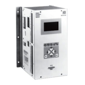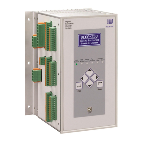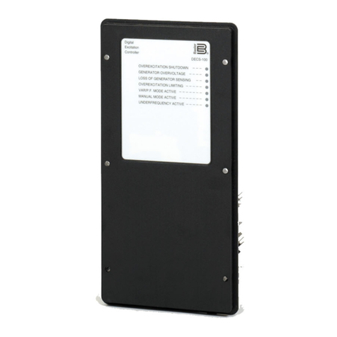
DECS-400 Digital Excitation Control System
FEATURES/FUNCTIONS, continued
8
Stator Current Limiter
The stator current limiter (SCL) senses the level of
stator current and limits it to prevent stator overheat-
ing. The SCL operates in all modes except FCR. In
FCR mode, the DECS-400 provides indication that a
stator overcurrent condition exists, but limiter action is
inhibited. Two SCL current levels are provided: high
and low. The generator can operate continuously at
the low SCL level, but only for a programmed time at
the high SCL level.
Autotracking Between DECS-400 Operating Modes
DECS-400 is an intelligent device that can provide
autotracking (autofollowing) of the controlling mode by
the non-controlling modes. This allows the operator to
initiate a controlled, bumpless transfer of the DECS-
400 between operating modes with minimal distur-
bance to the power system. This feature can be used
in conjunction with a set of protective relays to initiate a
transfer to a backup mode of operation, such as FCR
mode, upon the detection of a system failure or fault,
such as loss of sensing.
Autotracking between DECS-400 Units
The DECS-400 is also designed to automatically track
a second DECS-400 unit using dedicated communica-
tion ports on the two units. A backup DECS-400
controller can be placed in service and programmed
to track the control output of the primary DECS-400. In
the unlikely event of a failure of the first DECS-400,
protective relays can initiate a transfer of control from
the first to the second DECS-400 with minimal system
disturbance.
Protective Functions
The protective functions built into the DECS-400 may
be used as backup to the primary protection relays
and can be assigned to up to six programmable output
contacts via the PC software. The protection features
offer fully adjustable tripping levels and time delays.
The protective features are as follows:
• Generator Overvoltage* • Microprocessor Watchdog
• Generator Undervoltage* • Loss of Field Isolation Transducer
• Field Overvoltage* • Volts/Hertz Protection
• Field Overcurrent* • Exciter Diode Open
• Field Overtemperature* (Brushless App.)
• Loss of Field* • Exciter Diode Shorted
• Loss of Voltage Sensing (Brushless App.)
The functions marked with an asterisk (*) have dual setting groups.
Integrated Logic
The DECS-400 utilizes integrated logic functionality in
the form of multiplexors, AND gates, OR gates, NOT
gates, and timer gates. Inputs to the logic are in the
form of discrete information including switching inputs,
system status data, protection status data, limiter status
data, alarm status data, and PSS status data. The
outputs of the logic module can be used to control the
relay outputs as well as various other functions inside
the DECS such as control functions (start/stop, mode
select, etc.), protection functions (Field Overvoltage
Enable, Field Overcurrent Enable, etc.), limiter func-
tions (OEL enable, UEL enable, etc.), and PSS func-
tions. BESTCOMS includes tools for customizing the
system control logic for specific applications.
Metering
The DECS-400 is provided with two programmable 4 to
20 mA analog meter drivers for the customer's use. The
meter side is isolated from the DECS-400 circuitry.
Either can be programmed to meter a broad range of
generator and system parameters. 64 parameters are
available.
Sequence of Events Recording (SER)
A sequence of event report (SER) is a very powerful
tool for reconstructing the exact timing of an event or
disturbance. The DECS-400 monitors its contact inputs
and outputs for changes of state, system operation
changes, and alarm conditions. If any of these events
occurs, the DECS-400 will log that event with a date
and time stamp using IRIG B or NTP and an internal
clock with optional battery backup, allowing the user to
analyze a chain of events with accurate information
regarding the sequence in which they occurred. The
DECS-400 can store 127 events in volatile memory,
and those events are retrievable using BESTCOMS.
Oscillography
The data recording feature can record up to six (6)
oscillographic records stored in volatile memory. A
battery backup comes standard to maintain operation
of the real-time clock in the event that control power is
lost. The user can select up to six (6) variables to be
monitored when triggered by the DECS-400
BESTCOMS, a Logic Trigger, or a Level Trigger.
Variables that can be selected are: generator voltage,
Minimum Excitation Limiter
The Minimum Excitation Limiter prevents the excitation
being supplied to the field of the generator from
dropping below safe operating levels. This prevents
the machine from possibly slipping poles and damag-
ing the machine. This action also limits the amount of
VARs being absorbed by the machine, based on user-
definable settings. An internally generated Under-
excitation Limiting (UEL) curve based on a
permissable VAR level at 0kW can be utilized, or a 5
point UEL curve can be created to match specific
generator char-acteristics. UEL Limiter action is
optional in FCR mode.


