NU-METRICS NITESTAR User manual

Models NS-50 / NS-60
SDM Software & GPS Capability
Page 18
9-1-1 Program
Page 26
Hyperterminal Set-Up Section
Page 40
NEW!
NEW!
NEW!
Vehicle-Installed Distance Measuring Instrument
INSTALLATION & OPERATION
REFERENCE GUIDE
www.nu-metrics.com
Accurate Distance Measuring From Your Vehicle!
NITESTAR OPERATION MANUAL
Copyright © 2004 Nu-Metrics. All rights reserved.
This document contains or refers to proprietar y information that is
protected by copyright or patents. Copying or other reproduction of
this document and associated software, for sale or distribution, is
prohibited without the prior written permission of Nu-Metrics.
Windows™is a trademark of the Microsoft®Corporation.
518 University Drive
Uniontown, PA 15401 • USA
Phone: (724) 438-8750 • Fax: (724) 438-8769
www.nu-metrics.com
Nu-Metrics, Hi-Star and Highway Data Management (HDM) Software are trademarks of Nu-Metrics.
Copyright © 2004 Nu-Metrics. All Rights Reserved.
PRINTED IN THE U.S.A. REV 10/6/2004

TABLE OF CONTENTS
NITESTAR NS-50 and NS-60 . . . . . . . . . . . . . . . . . . . . . . . .2
Theory of Operation . . . . . . . . . . . . . . . . . . . . . . . . . .2
Automatic Error Correction (AEC) . . . . . . . . . . . . . . . .3
INSTALLATION
Mounting The Nitestar . . . . . . . . . . . . . . . . . . . . . . . .3
Mounting The Terminal Block . . . . . . . . . . . . . . . . . . .3
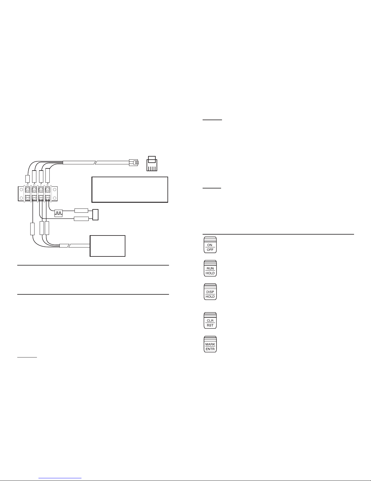
Wiring The Nitestar . . . . . . . . . . . . . . . . . . . . . . . . . .4
KEY DESCRIPTIONS
On/Off . . . . . . . . . . . . . . . . . . . . . . . . . . . . . . . . . . .5
Run/Hold . . . . . . . . . . . . . . . . . . . . . . . . . . . . . . . . .5
Disp/Hold . . . . . . . . . . . . . . . . . . . . . . . . . . . . . . . . .5
Clear/Reset . . . . . . . . . . . . . . . . . . . . . . . . . . . . . . .5
Mark/Enter . . . . . . . . . . . . . . . . . . . . . . . . . . . . . . . .5
Calibrate . . . . . . . . . . . . . . . . . . . . . . . . . . . . . . . . . .6
Unit . . . . . . . . . . . . . . . . . . . . . . . . . . . . . . . . . . . . .6
Pre Distance . . . . . . . . . . . . . . . . . . . . . . . . . . . . . . .6
Up/Down . . . . . . . . . . . . . . . . . . . . . . . . . . . . . . . . .6
Brightness (Backlight) . . . . . . . . . . . . . . . . . . . . . . . .6
Print . . . . . . . . . . . . . . . . . . . . . . . . . . . . . . . . . . . . .7
Speed Display . . . . . . . . . . . . . . . . . . . . . . . . . . . . . .7
Periodic Distance Interval . . . . . . . . . . . . . . . . . . . . . .7
Program Select . . . . . . . . . . . . . . . . . . . . . . . . . . . . .7
Memory View . . . . . . . . . . . . . . . . . . . . . . . . . . . . . .7
CALIBRATION . . . . . . . . . . . . . . . . . . . . . . . . . . . . . . . . . .7
Pre-Calibration Procedures . . . . . . . . . . . . . . . . . . . . .7
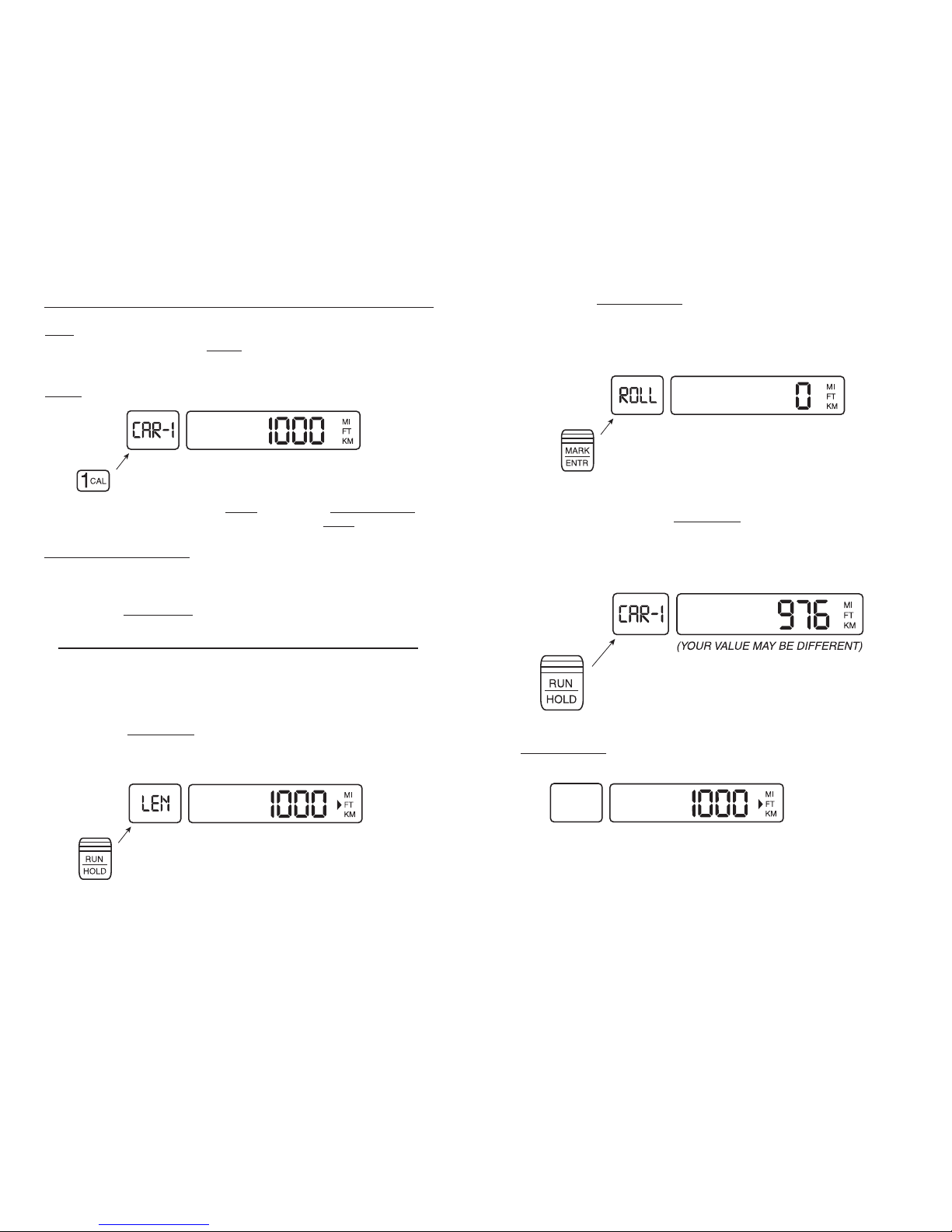
Instrument Calibration . . . . . . . . . . . . . . . . . . . . . . . .8
Calibration Summary (Automatic) . . . . . . . . . . . . . . .10
Calibration Summary (Manual) . . . . . . . . . . . . . . . . .10
MEMORY . . . . . . . . . . . . . . . . . . . . . . . . . . . . . . . . . . . .11
Storing Events to Memory . . . . . . . . . . . . . . . . . . . .11
Recalling Events from Memory . . . . . . . . . . . . . . . . .13
Memory Store Summary . . . . . . . . . . . . . . . . . . . . . .14
Store Memory Locations . . . . . . . . . . . . . . . . . . . . . .14
Printing Memory . . . . . . . . . . . . . . . . . . . . . . . . . . .15
Changing Memory Output Format . . . . . . . . . . . . . . .16
Plain Language Events . . . . . . . . . . . . . . . . . . . . . . .16
Memory Recall Summary . . . . . . . . . . . . . . . . . . . . .17
SURVEY DATA MANAGEMENT SOFTWARE . . . . . . . . . . . . .18
GPS System Overview . . . . . . . . . . . . . . . . . . . . . . .18
GPS Receiver Overview . . . . . . . . . . . . . . . . . . . . . .18
GPS Specifications . . . . . . . . . . . . . . . . . . . . . . . . . .19
PERIODIC DISTANCE INTERVAL (PDI)
Wiring . . . . . . . . . . . . . . . . . . . . . . . . . . . . . . . . . . .19
TTL PDI Connection . . . . . . . . . . . . . . . . . . . . . . . . .19
TTL PDI Wiring . . . . . . . . . . . . . . . . . . . . . . . . . . . . .20
12V PDI Connection . . . . . . . . . . . . . . . . . . . . . . . . .20
Setting PDI Distance . . . . . . . . . . . . . . . . . . . . . . . .20
Setting PDI Duration (Time) . . . . . . . . . . . . . . . . . . .21
Setting PDI Duration (Distance) . . . . . . . . . . . . . . . .21
Inside Front Cover
Setting the Type of PDI . . . . . . . . . . . . . . . . . . . . . .22
Low Going High (PDI Output) . . . . . . . . . . . . . . . . . .22
High Going Low (PDI Output) . . . . . . . . . . . . . . . . . .23
Flip Flop (PDI Output) . . . . . . . . . . . . . . . . . . . . . . . .23
Advanced PDI Uses . . . . . . . . . . . . . . . . . . . . . . . . .24
Set Count Increment . . . . . . . . . . . . . . . . . . . . . . . .24
Set Count Pre-Distance . . . . . . . . . . . . . . . . . . . . . .25
Summary PDI Keys . . . . . . . . . . . . . . . . . . . . . . . . . .25
PDI Count Use . . . . . . . . . . . . . . . . . . . . . . . . . . . . .25
EMERGENCY 9-1-1 PROGRAM . . . . . . . . . . . . . . . . . . . . .26
Set Count Increment . . . . . . . . . . . . . . . . . . . . . . . .26
Set Count Pre-Distance . . . . . . . . . . . . . . . . . . . . . .27
AUXILLARY PROGRAMS . . . . . . . . . . . . . . . . . . . . . . . . . .27
Self Test (PRM 1) . . . . . . . . . . . . . . . . . . . . . . . . . .28
Speed Trap (PRM 6) . . . . . . . . . . . . . . . . . . . . . . . . .28
Begin / End (PRM 15) NS-60 Only . . . . . . . . . . . . . . .29
Calculation Programs . . . . . . . . . . . . . . . . . . . . . . . .29
Area Calculation (PRM 10) . . . . . . . . . . . . . . . . . . . .30
Volume Calculation (PRM 11) . . . . . . . . . . . . . . . . . .30
Cost Calculation (PRM 12) . . . . . . . . . . . . . . . . . . . .30
Tonnage Calculation (PRM 13) . . . . . . . . . . . . . . . . .31
Tonnage Cost (PRM 14) . . . . . . . . . . . . . . . . . . . . . .31
Time Speed Delay Use (PRM 30) . . . . . . . . . . . . . . . .32
Time Speed Delay Limits . . . . . . . . . . . . . . . . . . . . . .33
Printer Use . . . . . . . . . . . . . . . . . . . . . . . . . . . . . . .33
SERIAL I/O
Data Format . . . . . . . . . . . . . . . . . . . . . . . . . . . . . .33
Serial Connector Diagram . . . . . . . . . . . . . . . . . . . . .34
Operation . . . . . . . . . . . . . . . . . . . . . . . . . . . . . . . .34
Baud Rate Setting . . . . . . . . . . . . . . . . . . . . . . . . . .34
DPU-414 PRINTER OPERATING INSTRUCTIONS . . . . . . . . . .35
Operating The Printer . . . . . . . . . . . . . . . . . . . . . . . .35
Functions That Use The Printer . . . . . . . . . . . . . . . . .35
Charging The Printer . . . . . . . . . . . . . . . . . . . . . . . .35
Opening The Paper Holder . . . . . . . . . . . . . . . . . . . . .36
Loading The Paper . . . . . . . . . . . . . . . . . . . . . . . . . .36
General Specifications (DPU-414) . . . . . . . . . . . . . . .37
TROUBLESHOOTING
Determining The Problem . . . . . . . . . . . . . . . . . . . . . . . . .37
Instrument is Operational But Won’t Count . . . . . . . . . . . .38
WARRANTY
Limited Warranty . . . . . . . . . . . . . . . . . . . . . . . . . . . . . . .39
HYPERTERMINAL STEP-BY-STEP GUIDE . . . . . . . . . . 40 – 44
SPECIFICATIONS
Nitestar Specifications . . . . . . . . . . . . . . . . . . . . . . . . . . .45
CALIBRATION LOG WORKSHEET . . . . . . . . . . . . . . . . . . . 46
NITESTAR RETURN FORM . . . . . . . . . . . . . . . . . . . . . . . . 47
1

NITESTAR MODELS NS-50 AND NS-60
The Nu-Metrics NITESTAR Vehicle Installed Distance Measuring
Instruments are available in two models; the NS-50 and the NS-
60. Both models are easy-to-use distance measuring instruments
(DMI) that facilitate land measurements from the convenience of
your automobile. The model NS-50 includes features required for
most basic surveys and applications.
The NS-60 includes all of the features of the NS-50 with the addi-
tion of a RS-232 Serial Port for connection of a serial printer, lap-
top computer, or GPS unit. With the RS-232 serial option and a
laptop computer, it is possible to conduct a complete highway
survey and then print directly to a 40 to 80 column serial printer.
DISTANCE MEASURING INSTRUMENT (DMI)
THEORY OF OPERATION
For electronic measurement of distance; a proximity sensor,
mechanical transmission sensor or electronic interface adapter is
used to provide speed pulses to the NITESTAR DMI for distance
measurements. How the DMI calculates distance is relatively
simple for each of the sensors.
The proximity sensor divides the vehicle tire into pie sections by
equally spaced targets attached to the rim. The spacing distance
between each target projects the proportional distance of the
outer circumference of the tire. For illustrative purposes, assume
a 15 inch tire has an average rolling circumference of 7.16 feet.
The distance between targets is representative of one eighth of
the circumference, which in this example is 0.895 feet. This sen-
sor can also be mounted to make use of the drive shaft of a vehi-
cle and positioned to read the knuckles of the u-joint or a tar-
get(s) attached to the u-joint or the drive shaft.
The transmission sensor transmits six pulses for each revolution
of the internal disk. Since most automobile speedometers are
based on 1000 revolutions per mile, approximately 6000 pulses
per mile are obtained. Dividing the pulses received (6000) into
the course length (5,280 feet) shows that each pulse represents
0.880 feet (5,280 divided by 6,000 = 0.880).
The electronic interface amplifier takes pulses already generat-
ed by the vehicle’s existing speed sensor and conditions this sig-
nal. Most vehicle sensors generate more pulses than the DMI
needs so the electronic interface includes a divider circuit. This
circuit changes the 100,000 pulse/mile vehicle sensor pulse out-
put to the 6,000 per mile required by the DMI.
2
AUTOMATIC ERROR CORRECTION (AEC)
AEC is a software generated program that uses velocity and time
calculations to help compensate for errors from the sensor equip-
ment. This is accomplished by constantly comparing the duration
of one sensor pulse to a subsequent pulse. When a pulse is
missed, AEC will flash and the DMI will correct the count. The
AEC will flash constantly on the left-hand side of the distance
screen when sporadic pulses are received, indicating that a prob-
lem exists and must be corrected.
INSTALLATION
NOTE: You may want to locate a garage or speedometer shop in your
area to perform the installation of the sensor and DMI instrument.
MOUNTING THE NITESTAR
The NITESTAR is designed to be mounted using the supplied
bracket or self-adhesive Velcro®strip fasteners that are provided
for direct mount. Determine the location where you will mount the
DMI in the vehicle. This will assist in determining how to route
the power cable for the unit. The DMI should be angled so the
operator is able to see the display and keyboard. Remove the self-
adhesive protective covering from one of the Velcro fastener
strips. Place the sticky side down at the location where you are
locating the DMI. Remove the self-adhesive protective covering
from the matching strip and press firmly to the back of the DMI.
Mount the DMI to the first strip. If using the bracket, repeat the
above procedures and fasten the DMI to the bracket before fol-
lowing the remaining steps.
– WARNING –
Do not mount a Nitestar in any area that may block the driver's
view or cause other obstructions.
MOUNTING THE TERMINAL BLOCK - CAUTION!
All wiring and materials should be installed and routed as far
away as possible from spark plug wires, ignition coil wire, mani-
fold and exhaust pipes. (Use the cable ties supplied with your
Installation Kit to secure wires away from these areas.)
Using the #6-32 screws from the installation kit, mount the ter-
minal block and electronic interface (if used) under the instru-
ment panel near the drivers seat. The fender well inside the
engine compartment on the driver’s side is an optional mounting
location. If using the proximity sensor or mechanical transmis-
sion sensor, follow the directions provided with the sensor. Insert
3

the DMI wiring harness into the power socket on the DMI. Route
the wire lug end of the wiring harness (telephone cable) from the
DMI location to the terminal block. Wire the cable to the termi-
nal block as shown in the drawing.
– WARNING –
Safety goggles and protective clothing should be worn at all
times when working on or near the vehicle battery or the associ-
ated battery cables.
WIRING THE NITESTAR - CAUTION!
Failure to connect the power and ground wires directly to the
battery may cause engine noise to interfere with the operation of
the DMI. Be sure to connect power and ground wires directly to
the battery terminals.
Connect the Red (power) and Black (ground) wires to the ter-
minal block as shown.
Connect the other end of the Black (ground) wire to the nega-
tive terminal of the battery. Remove the fuse and connect the red
(power) wire to the positive terminal of the battery.
NOTE: (DO NOT INSERT FUSE UNTIL INSTALLATION IS COM-
PLETE AND UNIT IS READY TO BE POWERED UP.)
4
TELEPHONE-TYPE FLAT CABLE
(BLACK, 8 FT.)
TOTHE NITESTAR DMI
POWER CABLE
WIRE DIRECTLY TO
12 VOLT VEHICLE
BATTERY (CONNECT LAST)
250 volt
1 amp fuse
GREEN
BLACK
WHITE
RED
BLACK
YELLOW
RED
+ RED
- BLACK
ELECTRONIC
INTERFACE SENSOR
or the
TRANSMISSION
INTERFACE SENSOR
SENSOR
MOUNT TERMINAL
BLOCK TO FENDER
WELL USING #6-32
METAL TAP SCREWS
CABLE FRONT VIEW
NITESTAR FUNCTIONS
PIN 1
PIN 2
PIN 3
PIN 4
= BLACK
= RED
= GREEN
=YELLOW
= GROUND
= PDI (5V SIGNAL)
= SIGNAL IN
= +12v DC
1234
WIRING A TRANSMISSION OR ELECTRONIC
INTERFACE SENSOR or… SEE THE PROXIMITY
SENSOR WIRING DIAGRAM (Inside Back Cover)
NOTE: Depending on the terminal block location selected,
either the wiring harness from the DMI or the power cable from
the battery will need to be routed through the vehicle firewall.
Usually this can be through an existing rubber grommet. This
could be where the speedometer cable or other wiring passes
from the passenger compartment to the engine compartment. If
no existing grommet or hole can be located, you may have to
carefully (do not damage existing wiring or items mounted on the
firewall) drill a 3/8 inch hole through the firewall. If a new hole
is made you should seal the hole when finished with an electrical
or waterproof putty or sealant.
NOTE: Actual sensor installation instructions may differ from
those shown. Follow the installation instructions included in your
sensor kit.
Use the cable ties supplied to tie off the wiring harness and
power cable neatly so they do not interfere with vehicle operator
or operation. When all installation is complete, replace the fuse
and power up the unit.
KEY DESCRIPTIONS
Turns the unit ON & OFF.
Depress the button for approximately 2 seconds to turn
the unit OFF.
STOPS & STARTS the COUNT. When NOT counting,
COUNT/HOLD flashes on the status display.
STOPS or freezes the display, DMI is still counting inter-
nally but the display value is stopped so you may write it
down. The words DISPLAY/HOLD will flash in the status
window when the instrument is in hold.
Depress the DISPLAY/HOLD key to resume.
Sets the distance value to ZERO.
(Same as PRINT key) : Also, marks an INTERVAL on the
display. When the DMI is counting, depressing the key will
set the current distance in the display window. The next
time the key is pressed the display will show the elapsed
distance from the last mark. DIAGRAM ON PAGE 6.
5

Prints data to the RS-232 output and updates INTERVAL.
If the RS-232 option is available the DMI will output...
Event # Distance Interval Speed <Return>
1. 12345 0 35
2. 12445 100 37
... each time MARK/ENTR or PRINT key is depressed
See Calibration Section
Changes distance units on display each time the key is
pressed. Units are: FEET, MILES and KILOMETERS.
Allows entry of a specific starting distance (pre-distance)
other than 0 Feet, Miles or KM. To set a specific
starting distance, clear the DMI before entering distance,
press 3PD, enter distance, then press MARK/ENTER.
The number entered can also be added to the current
distance displayed. For example, if the current distance
displayed is 100 Feet and a number of 30 is entered,
then the displayed distance will be 130 Feet.
Toggles the DMI between counting DOWN and UP. The
count direction is DOWN if the DN arrow is shown to the
left of the distance. If DN is NOT shown the unit is
counting UP. NOTE: When the DMI is counting DOWN
and reaches 0 it beeps and begins counting UP again.
Press to adjust the backlight brightness level. There are
three light levels and "off". The backlight consumes
power. Do not leave the backlight on when the vehicle
will not be in use for an extended period or the vehicle
battery could become depleted.
6
( same as MARK/ENTER key)
Changes the SPEED units displayed each time the key is
pressed. Units: Feet/Second -- Miles/Hour -- Kilos/Hour
See PDI Section
See Access to Memory Programs Section
See Memory Section
– IMPORTANT –
Your new Nitestar will be factory programmed with a calibration
number of 1000. This value should remain in the Nitestar until the
proper calibration procedure is completed as outlined in this man-
ual. If 1000 is not programmed in, manually type in “1000” and
press the MARK/ENTER key.
CALIBRATION OVERVIEW
The DMI works by counting pulses that are received from the sen-
sor. The number of pulses is different for each vehicle, so the
DMI must be calibrated for each vehicle.
The calibration number you find for your vehicle will be the num-
ber of feet the vehicle travels between each pulse multiplied by
1000. This number should be between 400 and 1400. If the
number is outside this range the accuracy of the DMI may be
adversely affected.
PRE-CALIBRATION PROCEDURE
1. Accurately measure a straight road course 1000’ long using a
tape measure or similar device. Mark the beginning and end with
a paint mark, stake in the ground, or other fixed object.
2. Check the air pressure in the vehicle tires. Make note of the
pressure and recheck each day before beginning use of the DMI.
3. Drive the vehicle for approximately 5 miles before running the
calibration course. This will help to match the same operating
temperatures that the tires will have during normal use.
7

INSTRUMENT CALIBRATION
1. Insure the DMI is in the FEET unit mode. If not, depress the
UNIT key until the DMI display shows FT.
NOTE: Nitestar Calibration MUST be done in FEET mode.
2. Insure the DMI is in COUNT/HOLD mode and depress the
1 CAL key. The display will show:
If the display is blank type in 1000 then press MARK/ENTER to
save. To return to calibration mode, press the 1CAL key again.
IMPORTANT NOTE: The NITESTAR can store up to 4 calibra-
tion numbers for 4 different vehicles. The display will show you
are working on the calibration number for car -1 and at present it
is 1000. You may step through the 4 calibration numbers by
pressing the DISP/HOLD key.
PROCEED TO THE START OF THE 1,000 FOOT COURSE.
Align a fixed point on the vehicle exactly with the marker for the
beginning of the calibration course. A piece of tape temporarily
fixed to the vehicle works well as a reference for the fixed point.
3. Press the RUN/HOLD key.
4. The display will show:
8
5. Depress MARK/ENTER. The display will show 0. When the
vehicle moves the display will show the pulses counted. The
value displayed is a tabulation of pulses counted by the instru-
ment and not a distance traveled.
NOTE: The SPEED window will NOT operate at this time.
6. At the end of the 1000 foot course, slow the vehicle carefully
so it is exactly aligned with the end of course marker. When the
car is aligned, press the RUN/HOLD key and the number in the
display will become your calibration number for this vehicle, (this
number should be between 400 and 1400).
Please write this num-
ber in the back of your manual or other location that will stay with
the vehicle.
Once you have recorded your calibration number, press
MARK/ENTER and your calibration number is stored in the DMI.
The display should show the course length.
7. Make sure this value is saved by turning the Nitestar off.
(Press the ON/OFF key).
8. If this is the first time you have calibrated a DMI, repeat the
procedure and see if you get the same calibration value.
9

CALIBRATION SUMMARY (AUTOMATIC)
With the instrument in COUNT/HOLD:
• 1CAL key -
• DISP/HOLD - Change car number
• RUN/HOLD - <1000’> in current units.
(Enter new course length if needed)
• MARK/ENTER -
Roll through calibration course!
• RUN/HOLD - (New cal number)
• MARK/ENTER to enter calibration number
(course length is displayed)
• ON/OFF (Stores your calibration number into memory)
CALIBRATION SUMMARY (MANUAL)
To enter in a known calibration number if your vehicle has
previously been calibrated.
With the instrument in COUNT/HOLD:
• 1CAL key -
• DISP/HOLD - Change car number
• Enter new calibration number (_ _ _ _ )
• MARK/ENTER - Will exit calibration mode
• ON/OFF (Stores your calibration number into memory)
10
MEMORY
The NITESTAR has 99 memory locations. Each location can store
an event and a distance. For example, 99 intersecting street
locations can be stored in memory with their corresponding dis-
tances. These values are saved in the permanent memory so
even after the unit is turned off and back on they can be recalled.
If you have the RS-232 option the values can be printed or trans-
ferred to a computer.
* Optional Survey Data Management software can be purchased
that will store an unlimited number of events and distances on a
laptop computer.
STORING EVENTS TO MEMORY
Insure that the DMI is in COUNT HOLD mode and your
UNIT
and
COUNT DIRECTION
are correct.
Depress 9PRM key.
The display will show:
Depress 0VIEW key followed by MARK/ENTR.
The display will show:
This starts the memory store sequence.
In this mode you can depress any of the following keys.
CLEAR : Clears all memory and exits memory mode.
PRINT : If you have the RS-232 option (NS-60 ONLY) and a print-
er, the DMI will print a copy of the survey header on the printer.
11

VIEW : Exits memory store. Now the NITESTAR is back to
standard operation mode.
RUN/HOLD : Will start the NITESTAR counting.
The count value will be changing depending on your speed. The
MARK number is the number of the memory location and the code
is the code that you wish to store there. Typing any numbers on
the number pad will store those digits into the code field. If you
wanted the code 82 you would type an 8 then a 2. Typing more
than two digits will just shift the digits to hold the last two you
typed. These will be the only values stored. You can have any
code from 00 to 99.
Pressing the DISP/HOLD key (NS-60 only) will print the current
distance, delta distance and code (either as a number or plain
language) to the printer. The value will NOT be stored in the
memory. This is useful if you just want to mark events but not
store them.
12
Depressing the MARK/ENTR key will store the code and the cur-
rent distance into memory. When you do this the MARK value
will go up by one and the code will become 00 again.
This would have stored a code 82 at distance 3216 in location
number one (1). Now we are ready to enter location two (2).
You can continue in this way until all 99 locations are used and
the NITESTAR will automatically leave STORE MEMORY mode.
If you did not clear memory and start the MEMORY STORE again
it will start at the next unused memory location. If the display
flashes -FULL- , all locations are full and you will have to clear
memory before you can store more data.
If you wish to EXIT STORE MEMORY before filling all 99 locations,
depress the RUN/HOLD key to place the instrument in COUNT
HOLD mode and then depress 0VIEW key, (the MARK/CODE mes-
sage will disappear).
RECALLING EVENTS FROM MEMORY
Insure that the DMI is in COUNT/HOLD mode and the desired
UNIT mode is set.
• Depress the 0VIEW key
This starts the memory recall sequence. The first window dis-
plays the address number (MARK) and the code at this address.
The main distance window displays the road track distance
stored in this memory location.
For address location 1 we have code 12 and a distance of 34,234
from the starting point.
13

At this point you can depress any of the following keys on the
next page:
MARK/ENTR : Moves to next memory location.
PRINT : If you have the RS-232 option and a printer attached it
will print all memory locations.
VIEW: Exits memory recall. Now the NITESTAR is back to stan-
dard operation mode.
MEMORY STORE SUMMARY
CLEAR : Clears all memory and exits memory mode.
PRINT : If you have the RS-232 option and a printer this will print
a copy of the survey header on the printer.
RUN/HOLD : Starts/stops NITESTAR counting
VIEW : Exits memory store. Now the NITESTAR is back to stan-
dard operation.
IMPORTANT NOTE: IF USING A NS-60, YOU MAY WISH TO PRINT
INFORMATION TO YOUR COMPUTER. YOU MAY DO THIS BY
USING THE HYPERTERMINAL APLLICATION. SEE SECTION 6
STORE MEMORY LOCATIONS
0 - 9 : While counting will enter in CODE values one at a time.
DISP/HOLD : While counting (NS-60 only) will print current dis-
tance and code value but NOT store them.
MARK/ENTR : While counting stores code and distance in mem-
ory location (NS-60 ONLY).
If you have the RS-232 option, each time you press MARK/ENTER
to store data in memory a line will print showing this data on the
printer.
See the RS-232/PRINTER section for further details.
14
PRINTING MEMORY
If you have the RS-232 option and a printer you can print a copy
of the survey header on the printer by depressing the 9PRM key,
0VIEW key, the MARK/ENTR key, and then the 6PRINT key.
The printout will look like this:
_ _ _ _ _ _ _ _ _ _ _ _ _ _ _ _ _ _ _ _ _ _ _ _ _ _
PROJECT NO: ________________ STATE:_____
DISTRICT/CITY/CO:_______________________
ROUTE:___________DIR:_______ OPR:_______
BEGIN:_______________ END:______________
_ _ _ _ _ _ _ _ _ _ _ _ _ _ _ _ _ _ _ _ _ _ _ _ _ _
Depress 0VIEW key to exit print header.
If you have the RS-232 option and a printer or are transferring
data to a computer the memory mode can print out a listing of
each event recorded along with its road distance and incremen-
tal distance from the previous event. For example, a printout
would look as follows:
Event# Distance Delta Code
1. 0 0 12
2. 123 123 5
3. 241 117 7
Event # : Count of events seen starts at 1 on each survey
Distance : Road track distance in current units (in example FEET)
Delta : Distance since last event (i.e. event 2 is 123 feet down
the road from event 1)
Code : The event code input by the user
15

CHANGING MEMORY OUTPUT FORMAT
The code output by the NITESTAR can be either the number input
by the user as shown above or you have the option of automati-
cally having that event number translated to a plain language
description. The standard NITESTAR has events 1 through 20
assigned as follows:
Code Plain Language Description
1 B.LINE Boundary Line (State, County, etc.)
2 INT B/W Intersection Both Ways (Crossroad)
3 INT R Intersection Right
4 INT L Intersection L
5 BEG 2 LN Begin Two Lane Roadway
6 BEG MULT LN Begin Multi-Lane Roadway
7 BEG BR Begin Bridge
8 END BR End Bridge
9 CUL Culvert
10 SCH.Z School Zone
11 RxR Railroad Crossing
12 STA.M Station or Mile Marker
13 SPD.L Speed Limit Change
14 U.POLE Utility Pole
15 PASS.R Pass Right (Centerline Markings)
16 PASS.B Pass Both Ways
17 PASS.L Pass Left
18 N.PASS No Passing Both Ways
19 DRW Driveway
20 M/B Mailbox
By default the NITESTAR prints the memory transfer as shown
above with the code values as numbers. If you would like to print
them using the plain language translations depress 9PRM key,
2UNIT key, then the MARK/ENTR key. The display will show:
16
After doing this your memory transfer would be:
Event# Distance Delta Code
1. 0 0 STA.M
2. 123 123 BEG 2 LN
3. 241 117 BEG BR
To switch back to code # output, depress 9PRM key, 3PD, then
the MARK/ENTR key.
The display will show:
MEMORY RECALL SUMMARY
MARK/ENTR : Moves to next memory location.
PRINT : If you have the RS-232 option and a printer attached,
all memory locations will be printed.
VIEW : Exits MEMORY RECALL.
The NITESTAR is back to standard operation mode.
PGM2 : Set memory transfer to show codes as
plain language (—PL—)
PGM3 : Set memory transfer to show codes as
#’s (—CODES—)
17

SURVEY DATA MANAGEMENT (SDM) SOFTWARE
Survey Data Management software is designed to provide the ability
to organize, view,and report information collected during various sur-
veys on or off the road. With the new WINDOWS SDM software, report-
ing is simplified with “Crystal Reports™” generated output. The ability
to export to other WINDOWS applications is also available. Data is
stored in Microsoft Access format.
KEY FEATURES:
• Vehicle Calibration for up to 4 Vehicles
• Customizable KEY DEFINITIONS for each user or application
• Ability to operate the NITESTAR remotely
• Ability to utilize optional GPS sensor
Initially, the SDM software is used in conjunction with the Nitestar 60
DMI, which is interfacing with a laptop computer during a survey.
After collecting and saving survey information, the saved information
can be viewed and organized at user’s convenience.
GPS - THE GLOBAL POSITIONING SYSTEM
GPS technology helps provide latitude, longitude, and altitude coordi-
nates for a user’s location regardless of the weather. The GPS course
acquisition code (CA) was designed by the United States Department of
Defense for use by the military and was made available for commercial
applications. Currently, GPS consists of a constellation of 27 earth
orbiting satellites approximately 12,000 miles above the Earth. GPS
satellites transmit radio signals containing time and orbital data to cal-
culate satellite position and user receiver data. GPS receivers monitor
the constellations and require signals from at least three satellites to
determine a two dimension position. A fourth satellite signal is required
to compute three-dimensional positioning for elevation or altitude.
SEE A SAMPLE SURVEY ON PAGE 48
THE NITESTAR GPS RECEIVER
The NITESTAR GPS RECEIVER provides GPS coordinates for applica-
tions that require vehicle mobility and in applications involving dense
urban centers and dense foliage where signals may typically be weak or
blocked. The receiver tracks all visible GPS satellites continuously and
uses all the measurements obtained to produce a GPS navigation solu-
tion. Position jumps caused by blockage in receivers with fewer chan-
nels are greatly reduced along with the effects of multi-path signals.
Road track data can be collected and stored by using a Laptop or
Notebook PC. SDM software is used to integrate inputs from the GPS
and the NITESTAR DMI distance data. GPS Receiver Architecture:
Twelve parallel satellite continuous tracking channels for fast acquisi-
tion and reacquisition. Enhanced algorithms provide superior navigation
performance in “urban canyon” and dense foliage environments.
18
GPS RECEIVER SPECIFICATIONS
Power: 5v DC ± 5%
Velocity: 0.1 meters/second
Time: 1 microsecond synchronized to GPS time
Solution Update Rate: 1 per second (1 Hz)
Dimensions: 2.6" (66mm) x 2.6" (66mm) x 0.28" (7mm)
Weight: 1.4 oz (40 g)
Operating Temp.: -4ºF to 185ºF (-20ºC to 85ºC)
Connector Type: USB or Serial RS-232
2D Accuracy (GPS): Horizontal < 7 meters (CEP), 11 meters 2 dRMS.
3D Accuracy (GPS): <14 meters (CEP).
Acquisition/Reacquisition Performance:
< 15 seconds Time to Cold Start < 120 seconds.
Antenna: GPS passive
Datums: WGS-84
Serial Interface: RS-232
PERIODIC DISTANCE INTERVAL - WIRING!
The NITESTAR produces a 5 volt, low current pulse (<5mA) on
the RED wire of the standard wiring harness. NOTE: If you wish
to control 12v, high current devices (>5mA), you will need the
P/N 1050 PDI amplifier unit. This unit will allow you to control
12v devices with up to 1 ampere of current. If you are using the
PDI pulse to go to a computer or other low current (<5mA…
sometimes called TTL) device you do not need the PN-1050
amplifier. Connect it directly to the RED wire from the NITES-
TAR. If you are in doubt about this connection please consult
your distributor or Nu-Metrics as a connection error can damage
the NITESTAR or your equipment.
TTL PDI CONNECTION
If the PDI pulse is to be directly connected to a computer or other
low voltage/low power device it can be wired as shown:
NOTE: Making the connection to external equipment requires
the users knowledge of the equipment and Nu-metrics will not be
able to support this application.
19

TTL PDI WIRING
The device is connected to the RED wire; a 47K Ωresistor is
necessary to supply the ground level to the device.
12 V PDI CONNECTION
See P/N 1050 Manual.
SETTING PDI DISTANCE
(i.e. feet/miles/kilos between pulses)
STEP 1 : Set the measurement units, (feet,miles or KM), you wish
to use for your PDI distance. Even though the default “1”
appears, you must re-enter the required PDI Distance number and
press MARK/ENTR.
STEP 2 : Next, press the following keys: 8PDI key, 2UNIT key
(DISTANCE), MARK/ENTR key.
20
MOUNT TERMINAL
BLOCK TO FENDER
WELL USING #6-32
METAL TAP SCREWS
TELEPHONE-TYPE FLAT CABLE
(BLACK, 8 FT.)
TOTHE NITESTAR DMI
POWER CABLE
WIRE DIRECTLY TO
12 VOLT VEHICLE
BATTERY (CONNECT LAST)
NITESTAR FUNCTIONS
PIN 1
PIN 2
PIN 3
PIN 4
= BLACK
= RED
= GREEN
= YELLOW
= GROUND
= PDI (5V SIGNAL)
= SIGNAL IN
= +12v DC
250 volt
1 amp fuse
GREEN
BLACK
WHITE
RED
BLACK
YELLOW
RED
PDI SIGNAL IS RED
+ RED
- BLACK
ELECTRONIC
INTERFACE SENSOR
or the
TRANSMISSION
INTERFACE SENSOR
SENSOR
TO TTL
DEVICE
(Jump to -Black to Battery)
BLACK
WHITE
BLACK
RED
RED
CABLE FRONT VIEW
1234
TTL PDI
WIRING
DIAGRAM
SETTING PDI DURATION
(TIME = milliseconds the pulse is ON)
STEP 1 : Press the following keys: 8PDI key, 3PD key (number
of milliseconds), MARK/ENTR key. 1000 mill-secs = 1 sec.
STEP 2 : Remember, depending on your PDI distance, if your pul
es are too long they can run together at high speeds. If you use
pulses of less than 10 milliseconds duration then this should not
happen at normal highway speeds. If you need longer pulses use
the following formula to find what your absolute maximum speed
will be.
SPEED = (PDI Length) * 1000/ (PDI Time in milliseconds)
This speed will be in Length/second units and use your standard
conversion factors to change to KPH or MPH
For feet/second -> MPH multiply by 0.6818
For kilometers/sec -> KPH multiply by 3600
SETTING PDI DURATION (DISTANCE)
(i.e. feet/miles/kilos pulse is ON)
STEP 1 : Press the following keys:
8PDI key, 3PD key, DISP/HOLD key, (DISTANCE) MARK/ENTR key.
21

STEP 2 : At the PLEN prompt, enter the length in current units
you would like your pulse to be on. You can set the pulse to be on
for a set length.
The length duration will have an error = +/- CALIBRATION
NO./1000 FEET. If you had a calibration number of 800, your
PDI pulse duration would be your set length +/- 0.8 FOOT.
The duration is limited to 32,768*
CALIBRATION NO. / 1000 FEET.
If you had a calibration # of 700 your max duration would be:
MAX Duration = 32,768* 700/1000 = 22,958 Feet.
or 0.034 mi… or 0.044 km
If you enter a value over this it will fold your input value back
down into this range.
IMPORTANT NOTE: Do not set this length greater than the
PDI distance. If you have a PDI distance of 100 feet, do not set
the duration to 200 feet. After the first pulse the PDI pulse will
go on then never shut off.
SETTING THE TYPE OF PDI
The device that uses the PDI signal sometimes has certain
requirements for the signal. The NITESTAR can produce three
types of PDI. Let us take for example a PDI set for every 10 feet
and a duration of 1 millisecond.
LOW GOING HIGH (DEFAULT SETTING)
The default setting would be with the output normally low (0
volts) and pulsing high at each PDI distance. If you want to return
to this default setting depress the following sequence of keys:
8PDI key, 6PRINT key, MARK/ENTR key.
22
The output shown below is for Low Going High:
HIGH GOING LOW
If you want the output normally low ( 0 volts) and pulsing LOW at
each PDI distance depress the following sequence of keys:
8PDI key, 5BRIGHTNESS key, MARK/ENTR key.
The output shown below is for High Going Low:
FLIP FLOP
If you want to set FLIP/FLOP high on every other 10 ft stretch
depress the following sequence of keys: 8PDI key, 4UP/DOWN
key, MARK/ENTR key.
23

…and your output would be:
Note that the duration does not apply to this one, it just alter-
nates HIGH & LOW on each PDI distance.
ADVANCED PDI USES
As pre-mentioned a count of the PDI pulses can be displayed in
the INTERVAL window. You must set the Count Increment and
optionally the Starting Value. The INTERVAL window will then dis-
play the Starting Value and then with the vehicle moving and the
COUNT/HOLD off, the INTERVAL window will display the Count
Increment value as derived from the PDI pulse output.
SET COUNT INCREMENT
The Count Increment number is the amount of PDI pulses required
to increment the count displayed in the interval window. If you
set a PDI distance of 50 feet and a count increment of 1 you will
see the count displayed in the interval window every 50 feet.
You MUST set the count increment for the display PDI count func-
tion to be displayed. To set the increment count value depress
the following sequence of keys: 8PDI key, 7SPEED key, and
choose the INCREMENT DISTANCE.
Please note that after you
press the “7 SPEED” key, the default “1” will appear.
At this
time, re-enter whatever value you choose. Press MARK/ENTR.
While entering increment distance depressing CLEAR/RST key
will set the distance and PDI count to 0.
While Count Increment is running
the INTERVAL will NOT be displayed.
24
SET COUNT PRE-DISTANCE
To have your PDI count to start at a value other than 0 depress
the following sequence of keys: 8PDI key, 8PDI key again,
(ENTER PREDISTANCE VALUE), MARK/ENTR key. The value will
appear in the INTERVAL window.
SUMMARY PDI KEYS
First Press 8PDI and then:
2.) - Set PDI Distance
3.) - Set PDI Duration by TIME
3.) - Set PDI Duration by DISTANCE - (DISP/HOLD)
4.) - Set Flip/Flop PDI (High then low on alternate PDI distances)
5.) - Set HIGH going LOW signal
6.) - Set LOW going HIGH (Standard)
7.) - Set distance increment for PDI Count dis play
8.) - Set initial value for PDI Count display
CLEAR - Turn OFF PDI (& PDI count display)PDI
PDI COUNT USE
An example will make this function a little clearer. Many author-
ities are setting up 911 emergency call response systems. When
a person calls for help, the Emergency Response Center can, via
phone company equipment, determine the phone number of the
caller. The callers address can then be determined.
The Emergency Response Center can then dispatch police, fire
or ambulance teams to handle the problem. This may work well
except in rural areas when the addresses are undefined or Rural
Route box numbers. Emergency response teams may not know
how to locate the address. Rural governments are solving this
problem by naming all their roads (and putting up signs) and
assigning addresses to the houses on these roads. The phone
numbers are then associated with a street address that police,
fireman and ambulance drivers can find.
How do the local governments assign these addresses? After
naming the roads each house must be given a number. Each
house can not be numbered consecutively since new houses will
probably be built between existing houses and these places will
need numbers. If a standard lot width is determined (say 50’)
then every 50 feet assign a new address. This way you can num-
ber the houses now and when new houses are added you can give
them numbers in the correct order.
(continued…)
25

The DMI can be used to assist in this process. Begin your dis-
tance at the start of the road and at each house divide the dis-
tance by 50, for example, and you have the number. The DMI per-
forms this function and no calculations are necessary. With the
PRE-DISTANCE function of the DMI you can start your address
numbering from a known value. If a new house is added you
would not have to drive the entire road to locate a new address.
EMERGENCY 911 ADDRESSING PROGRAM
SETTING UNIT MEASUREMENT
The Unit Measurement is the distance segment used to deter-
mine a house number for E-911 addressing (i.e. 5.28 ft, 10 ft,
10.56 ft, 1 meter, and so on).
STEP 1 : Set the unit measurement (Feet, Miles or KM), you wish
to use for addressing. If using whole feet measurement, set unit
measurement to FEET. If using feet measurement with decimal
point set unit measurement to MILES. And, if you are using a
meter measurement set unit measurement to KM.
The MILES and KM unit measurement will display a whole digit
number with three decimal points. The third decimal point in
MILES unit measurement represents 1/1000th of a mile, or 5.28
feet. Also, the third decimal point in the KM unit measurement
represents 1/1000th of a KM, or 1 meter.
STEP 2 : To set the unit measurement; press this sequence of
keys, 8PDI key, 2UNIT key (DISTANCE), MARK/ENTR key.
NOTE : After you press the “2 UNIT” key, the default “1” will
appear. At this time re-enter the value of unit measurement need-
ed. Then press MARK/ENTER key.
SET COUNT INCREMENT
The Count Increment number is the amount of unit measurements
traveled to increment the count displayed in the interval window.
The Count Increment number displayed in the interval window, as
26
when you are measuring a street or road for addressing, is the
actual E-911 house number. For example, if you set a unit mea-
surement of 10 feet and a count increment of 1 you will have a
house number of 1 at the first 10 ft mark, a house number of 2 at
the 20 ft mark, a house number of 3 at the 30 ft mark, etc.
To set the count increment value depress the following sequence
of keys: 8PDI key, 7SPEED key, and choose the INCREMENT
DISTANCE.
Please note that after you press the 7SPEED key, the default “1”
will appear. At this time re-enter value of count increment need-
ed. Then press MARK/ENTR.
While entering increment distance, depressing CLEAR/RST key
will set the distance measurement and house number to 0.
SET COUNT PRE-DISTANCE
To have your count increment began at a certain value other than
0 depress the following sequence of keys: 8 PDI key, 8 PDI key,
(HOUSE NUMBER), MARK/ENTER key. The value will appear in
the INTERVAL window.
AUXILIARY PROGRAMS
The NITESTAR has other specialized functions that are accessed
by pressing the PRM key then a number key. These are functions
that are not needed all the time but do prove very useful to many
users.
(continued…)
27

To access, press the PRM key then enter in the selected program
number and press MARK/ENTR key to start the program. NOTE:
insure your instrument is in COUNT/HOLD mode before selecting
any auxiliary program. NITESTAR can have program numbers
from 0 to 255. Only a small fraction of this range is used and is
summarized below. Refer to the section in the function descrip-
tion for information on the use of this operation. Some of the func-
tions are described here. Others such as memory and baud rate
functions are described in MEMORY and SERIAL I/O sections.
Prm# Description Section Model
0 - Memory Mark Action Memory Sect All
1- Self-Test Operation Aux Programs All
2- Events as Words Memor y Sect NS-60
3 - Events as Numbers Memory Sect NS-60
5 - Set Baud Rate Serial I/O NS-60
6 - Speed Trap Aux Programs All
9- Set Display Flash Rate Aux Programs All
10 - Calculate AREA Aux Programs All
11 - Caculate VOLUME Aux Programs All
12 - Calculate COST Aux Programs All
13 - Calculate TONNAGE Aux Programs All
14 - Calculate COST BY TON Aux Programs All
15 - Begin / End Accumulate Aux Programs NS-60
30 - Time Speed Delay Aux Programs NS-60
254 - COUNT TEST Aux Programs All
255 - DISPLAY TEST Aux Programs All
PROGRAM DESCRIPTIONS
PRM 1 (SELF TEST) NS-50/60
1: Place instrument in COUNT/HOLD mode.
2: Press PRM, 1, MARK/ENTR.
3: Press the RUN/HOLD key to release the COUNT/HOLD mode.
The instrument will generate its own sensor signal. This is useful to simulate
vehicle signals. It tests all of the instrument functions except the sensor input
circuit. When in Self Test all annunciators on the display will flash.
4: To EXIT Self-test insure instrument is in COUNT/HOLD mode and
press PRM1, MARK/ENTR.
PRM 6 (SPEED TRAP) NS-50/60
This function is used to calculate the speed of a vehicle passing
between a predetermined set of markers.
1: With the instrument in COUNT/HOLD mode, set the desired speed
and distance units.
2: Press PRM, 6, MARK/ENTR to enter the speed trap program.
3: Display will show COURSE. Enter in the distance between the mark-
ers in the current units, (i.e. 100), and press MARK/ENTR.
28
4: As the vehicle passes the first marker, press MARK/ENTR.
(The speed display will blur).
5: As the vehicle passes the second marker, press MARK/ENTR again.
The vehicle speed will be shown in the SPEED display.
6: Go back to STEP 4 for the next vehicle.
7: To EXIT the speed trap program press CLEAR.
If you have the RS-232 option and a printer the NITESTAR will output a
count and speed each time the program calculates a new speed.
For example, 1.) 53 --- 2.) 61 ---- 3.) 47
PRM 15 (BEGIN/END) NS-60 ONLY
Insure the instrument is in COUNT/HOLD mode. Press PRM, 15,
MARK/ENTR. The display will show BE ON or BE OFF. If it says BE ON
then the program will begin to accumulate intervals. After BE ON the
next time you press PRINT or MARK/ENTR the printer will print:
<Event #> <Distance> <Delta Dist> <Speed> BEGIN
The next time you press MARK/ENTR it will print:
<Event #> <Distance> <Delta Dist> <Speed> END <Accum Distance>
1. 12365 0 25 BEGIN
2. 12466 101 25 END 101
3. 13466 1000 25 BEGIN
4. 13567 101 25 END 202
The <Accum Distance> will be the sum of the <Delta Distance>’s
between the
BEGIN/END
markers. You can use this to measure guard
rail for example. When you press MARK/ENTR it generates a BEGIN, the
next press is an
END
.
The distance between each
BEGIN
and
END
is accumulated and printed
at each
END
.
Insure instrument is in
COUNT/HOLD
mode and Press PRM, 15,
MARK/ENTR to exit the BEGIN/END Program.
CALCULATION PROGRAMS
These functions do a calculation with the distance shown on the display.
To use the calculations programs, first measure the desired distance
using the NITESTAR. Then with the road distance on the display you can
calculate the area, volume or amount of material for a paving or resur-
facing job. Insure the instrument is in the COUNT/HOLD mode for all the
calculation programs.
29

PRM 10 - AREA CALCULATION NS-50/60
This determines the area for a fixed lane width over distance displayed.
Press PRM, 10, MARK/ENTR
PROMPT INPUT
For FT/MI units For KM units
_______________________________
LANE Width in FEET Width in 0.1 meters (decimetres)
Enter correct width and press MARK/ENTR
~RESULT~
AREA AREA in SQ yards AREA in SQ meters
Depress PRINT to print results or MARK/ENTR to exit this calculation.
PRM 11 - VOLUME CALCULATION NS-50/60
For example, this is used to determine the volume of paving material.
For a given lane width, thickness of material and the distance; a volume
is computed. Insure the instrument is in the COUNT/HOLD mode.
Press PRM, 11, MARK/ENTR
PROMPT INPUT
For FT/MI units For KM units
__________________________________
LANE Width in FEET Width in 0.1 meters (decimetres)
DPH (Depth) Thickness in inches Thickness in cm
~RESULT~
VOLUME in CU yards VOLUM in CU meters
Depress MARK/ENTR key after each entry.
Press MARK/ENTR again, to exit this calculation.
PRM 12 - COST CALCULATION NS-50/60
This is used to estimate the cost of material for a job, the volume is cal-
culated as in PRM 11 and then is multiplied by a cost/cu yd or cost/cu
m. This yields a cost for the volume of material used. Insure instrument
is in COUNT/HOLD mode.
Press PRM, 12, MARK/ENTR
PROMPT INPUT
For FT/MI units For KM units
___________________________________
LANE Width in FEET Width in 0.1 meters (decimetres)
DPH (Depth) Thickness in in Thickness in cm
PRCE(Price) Material cost (e.g. $/cu unit) * 100
(If the cost was $3.46 / cu yd input 346)
~RESULT~
JOB- Distance * width * thickness * cost = $
(amount in cost units i.e. $’s).
Depress MARK/ENTR key after each entry, press MARK/ENTR again to
exit this calculation.
30
PRM 13 - TONNAGE CALCULATION NS-50/60
This is used to estimate the amount of material for a project, the vol-
ume is calculated as in PRM 11 and then is multiplied by lb/cu yd or
kg/cu m. This yields an estimate of the number of tons of material
needed. Insure instrument is in COUNT/HOLD mode.
Press PRM, 13, MARK/ENTR.
PROMPT INPUT
For FT/MI units For KM units
__________________________________
LANE Width in FEET Width in 0.1 metres (decimetres)
DPH Thickness in in Thickness in cm
DEN Material Density in lb/cu yd or kg/cu m.
If material density given in lb/sq yd * in
multiply by 36 to get lb/cu yd. If in kg/sq m *
cm multiply times 100.
~RESULT~
FILL Distance * width * thickness * density = mass
result in tons (metric or English).
Depress MARK/ENTR key, to exit this calculation.
PRM 14 - TONNAGE COST NS-50/60
This is used to estimate the cost of material for a job, the volume is cal-
culated as in PRM 11 and then is multiplied by lb/cu yd or kg/cu m.
This yields an estimate of the number of tons of material needed. Then
you input a cost/ton value. Insure instrument is in COUNT/HOLD mode.
Press PRM, 14, MARK/ENTR.
PROMPT INPUT
For FT/MI units For KM units
__________________________________
LANE Width in FEET Width in 0.1 metres (decimetres)
DPH(Depth) Thickness in in Thickness in cm
DEN Material Density in lb/cu yd or kg/cu m.
If material density given in lb/sq yd * in
multiply by 36 to get lb/cu yd. If in kg/sq m *
cm multiply times 100.
PRCE(Price) Material cost (e.g. $/ton) * 100
(If the cost was $3.46 / ton input 346)
~RESULT~
JOB Distance * width * thickness * density * cost = $
amt result in $ or currency units.
Depress MARK/ENTR key after each entry and press MARK/ENTR
again to exit this calculation. --- The NITESTAR will remember your
inputs so you won’t have to input the constants such as lane width or
cost each time. When the result is displayed it will stay until you press
the MARK/ENTR key. After that the original distance is restored.
31

PRM 30 - TIME-SPEED-DELAY (TSD) NS-50/60
Traffic engineers often use TIME-SPEED-DELAY (TSD) measurements
to evaluate roadways. They drive the road recording total trip time
and total distance. Then dividing total distance by total time to get
an average speed for the road segment. This measurement can be
done at various times (i.e. at night, rush hour etc.) measuring conges-
tion and other factors affecting traffic flow. The NITESTAR (50 & 60)
after revision 3.0 has this function built in. When running in TSD
mode, distance is accumulated and displayed as normal but the inter-
val window now displays the elapsed trip time in minutes and seconds.
The speed displayed is not the instantaneous speed but the average
computed from the total distance divided by the total time.
TIME-SPEED-DELAY USE
STEP 1 :Make sure your NITESTAR is version 3.0 or above, when you
turn it on make sure it shows 3.0 or greater in the interval window. (It
if does not ,contact your distributor or Nu-Metrics)
STEP 2 : Verify your Nitestar has been calibrated and is measuring dis-
tance correctly.
STEP 3 :Move to the start of the sur veyed road. Then press PGM30,
then MARK/ENTR. The display will then flash SP-DEL three times and
the distance, interval and speed will all be zero.
STEP 4 : The following keys are active now:
RUN/HOLD : Starts the distance,speed & elapsed time counters
DISP/HOLD : Freezes the distance, elapsed time & speed displays
UNITS : Changes distance units on display
SPEED : Changes speed units on display
CLEAR : In COUNT HOLD, exit TSD. (Otherwise ignored)
PRINT : In COUNT HOLD & Model 60 will print header.
Otherwise same as MARK/ENTR
MARK/ENTR : In Model 60 will print:
# Distance Delta Dist Elapsed Time Speed
STEP 5 : Run your route recording the time, speeds and distances.
On the Model 50 you will have to write them down. On a Model 60 the
values can be printed on a DPU-411 or captured on a computer.
STEP 6 :When you are done, go to COUNT/HOLD using the RUN/HOLD
key. Then press CLEAR to exit TSD mode. Use PRM30, MARK/ENTR
to enter it again for another run.
While running TSD you can press either DISP/HOLD or RUN/HOLD to
stop the display. These two have very different actions.
RUN/HOLD - Stops Time & Distance Count. Use to pause the survey.
DISP/HOLD - Holds the display ONLY.
Time and Distance continue to accumulate.
32
TIME-SPEED-DELAY LIMITS
The Time Speed Delay survey cannot run longer than 255 minutes
(4 hours 15 minutes). Beyond this point the printed time will be
incorrect. The time on the display will only go to 99 minutes
(1 hour 39 minutes). The speed results are correct after these
times but the displayed times will not be correct.
0 - 99 Min. Displayed time OK, Printed Time OK, Speed OK
100-200 Min. Displayed time off, Printed Time OK, Speed OK by 100 minutes
201-255 Min. Displayed time off, Printed Time OK, Speed OK by 200 minutes
256-∞Min. Displayed time off, Printed Time off , Speed OK
If you need longer times, consult Nu-Metrics. The NITESTAR-60
with a laptop computer can do longer surveys with TSD software.
PRINTER USE
If you have an NS-60 and a printer these functions will print out a
summary of the calculation. With the result displayed and the
printer ON ; pressing PRINT will print the following:
SERIAL INPUT / OUPUT
DATA FORMATS
BAUD Rates: 9600, 4800, 2400, 1200, 600, 300
(See Selection Method on the Next Page)
33
AREA Calculation
WIDTH: 10 FT
DIST: 1000 FT
AREA: 1111 SQ YD
VOLUME Calculation
WIDTH: 10 FT
HEIGHT: 6 IN
DIST: 1000 FT
AREA: 185 CU YD
COST Calculation
WIDTH: 10 FT
HEIGHT: 6 IN
DIST: 1000 FT
AMOUNT: 1.5
AREA: 185 CU YD
COST 283
TONNAGE Calculation
WIDTH: 10 FT
HEIGHT: 6 IN
DIST: 1000 FT
VOLUME: 185 CU YD
DENSITY: 3960 LB/CU YD
MASS: 366 TON
TONNAGE Cost Calculation
WIDTH: 10 FT
HEIGHT: 6 IN
DIST: 1000 FT
VOLUME: 185 CU YD
DENSITY: 3960 LB/CU YD
MASS: 366 TON
AMOUNT: 2.00
COST: 732

Full Duplex:
Front View Serial Connector (Nitestar Data Connector):
SERIAL OPERATION
The Nitestar has both serial in and out capability. Commands can
be input on serial input and distance, speed and time values are
output to serial out. The instrument can be completely controlled
over the serial lines. Anything the user can do from the keyboard
is duplicated in the serial commands. Also the instrument seri-
al baud rate can be set at any value from 9600 to 300 baud.
BAUD RATE SETTING
To select the proper baud rate depress the following sequence:
9PRM key, 5BRIGHTNESS key and MARK/ENTER.
The display will show:
STEP 1 : Press DISP/HOLD to step thru the baud rate choices.
STEP 2 : Press MARK/ENTER when the proper baud rate is dis-
played. Your baud rate is now selected.
34
PRINTER INSTRUCTIONS
The DPU-414 Printer is a portable thermal printer that can oper-
ate from an AC Power Adapter or from the built in rechargeable
battery system. The battery operated system has a typical run
time of 1,500 printed lines when fully charged.
The DPU-414 can be used in the vehicle to obtain a real-time
printout, or in the office to “dump” inventory data previously
stored in the Nitestar's Memory.
Remember to fully charge your printer before starting your sur-
vey & turn off the printer when not in use to preserve battery life.
OPERATING THE PRINTER
STEP 1 : Turn off printer power switch and Nitestar power switch.
STEP 2 : Connect printer & Nitestar with interface cable.
STEP 3 : Turn on power switches to the Nitestar & DPU-414.
Printer Status should be On Line, if not, make sure paper is
loaded and ready. (Loading the Paper)
STEP 4 : To advance the paper feed the printer must be in the Off
Line mode.
See function listing below for further detail about printer operation.
FUNCTIONS THAT USE THE PRINTER
Memory Dump . . . . . . . . . . . . .Memory Section 5
Print Key . . . . . . . . . . . . . . . .Key Descriptions Section 4
Speed Trap . . . . . . . . . . . . . . .Auxiliary Programs Section 6
Area Calculation . . . . . . . . . . .Auxiliary Programs Section 6
Volume Calculation . . . . . . . . .Auxiliary Programs Section 6
Job Cost . . . . . . . . . . . . . . . . .Auxiliary Programs Section 6
CHARGING THE PRINTER
STEP 1 : Turn off power switch.
STEP 2 : Plug-in DC plug on the AC adapter into the power supply
jack on the printer.
STEP 3 : Plug the AC adapter into an outlet.
STEP 4 : Turn power on.
To remove the AC adapter, first turn off the power switch, then
unplug the AC adapter and the DC plug.
35

OPENING THE PAPER HOLDER
STEP 1 : Using your thumb, pull paper holder cover towards back
of the printer. (Unlock it.)
STEP 2 : Lift cover upwards.
When closing and locking the paper holder cover, follow the
above instructions in reverse
LOADING THE PAPER
STEP 1 : Turn on power switch.
STEP 2 : Cut the paper in an inverted V (see figure)
STEP 3 : Open paper holder cover.
STEP 4 : Push top of paper into inlet, and feed it by hand until you
can see top of paper from paper cutter. The paper is easier to feed
if placed on the cover.
STEP 5 : Keep pressing the paper feed switch until the paper
feeds straight and smoothly. When the paper is correctly set, the
off line lamp stops flashing and stays lit instead.
NOTE : Red lines appear on both sides of the paper when paper is
about to run out. The outside of the thermal paper is at the front.
36
PRINTER SPECIFICATIONS (DPU-414)
Printing Method: Thermal serial dot
Character: 9 high x 8 wide dot matrix
Columns: 40
Printing Direction: unidirectional, bi-directional logical seek
Total number of dots: 8 x 320 dots / line
Printing Direction: unidirectional
Bi-directional logical seek
Printing width: 89.6mm
Printing speed: 37.5 cps
External Dimensions: 162 x 240 x 58.5 mm
Mainframe weight: 950g
PAPER
Jujo Paper Co. TP411-28CL
Paper width 112 mm, roll diameter 48mm, roll length 28m
OPERATING CONDITIONS
1. Operating temperature and humidity 0-40°C, 30-85% RH
2. Storage temperature and humidity -20-60°C, 5-90% RH
This section was an overview of the DPU-414 and contains enough information
to conduct a typical survey using the Nitestar. For more detailed information
about the DPU-414 please refer to the Printers Operation Manual.
TROUBLESHOOTING
If your Nitestar DMI appears to be inoperative, the following steps
should be taken in order to determine if you have an installation
problem, a sensor problem or an instrument problem.
1. Both +12 Volts and Ground to the terminal block MUST be
obtained directly from the vehicle’s battery terminals. Check to
make sure your black & red wires are connected direct to the
vehicle battery. (Remember the In Line Fuse is required). Always
wear safety goggles and protective clothing.
2. Make sure power is going to the instrument by checking with
a meter or continuity tester. Refer to the Operating Manual,
Installation Procedures which will show the pin’s location. If you
do not have power, check for a loose connection or blown fuse.
Always wear safety goggles and protective clothing.
3. Plug in the Nitestar and turn it on. It should begin its Self-
Check, when completed (0) should be displayed in the Speed &
Count windows. COUNT HOLD will flash in the function window.
37
This manual suits for next models
2
Table of contents
Popular Measuring Instrument manuals by other brands

Hioki
Hioki PW3198 instruction manual

Endress+Hauser
Endress+Hauser Proline Prowirl D 200 Brief operating instructions

wtw
wtw Cond 3110 quick start guide

Renishaw
Renishaw APCA Series Installation and user guide

Luster Leaf
Luster Leaf 1835 user manual

Crompton
Crompton Tyco Electronics SWITCHBOARD INTEGRA 1540 Installation and operating instructions