Chemitec 50 SERIES User manual

50 SERIES 8 PARAMETERS
MULTIPARAMETER PLUG & PLAY
ANALYZER
TECHNICAL MANUAL
P/N: ………………….
Rev. 1 Ver. 1
EDITION Agoust 2018 draft

50 Series 8P
MULTIPARAMETER PLUG & PLAY ANALYZER
TECHNICAL MANUAL P/N XXX-0000 Rev.4 Ver.1.1
II
GENERAL CLAUSES
Despite the fact that the utmost attention has been given taken
in the preparation of this document, CHEMITEC s.r.l. cannot
guarantee the accuracy of all information contained and cannot
be held responsible for any consequent mistakes or damages
that may arise from its use or application.
The products, materials, software and services presented in
this document are subject to development and with regards to
presentation and performance characteristics, CHEMITEC s.r.l.
reserves the right to carry out any modifications without prior
notice.
COPYRIGHT
The reproduction or copy of this manual, even partial, and
using any procedure is strictly prohibited.
AUTHORISED TECHNICAL SUPPORT CENTRES
CHEMITEC s.r.l.
Via Isaac Newton, 28 – 50018 Scandicci - FIRENZE

50 Series 8P
MULTIPARAMETER PLUG & PLAY ANALYZER
TECHNICAL MANUAL P/N XXX-0000 Rev.4 Ver.1.1
III
INDEX
1 GENERAL ...............................................................................................................................................................1
1.1 INFORMATION ON THE MANUAL..............................................................................................................1
1.1.1 CONVENTIONS ........................................................................................................................................1
1.2 DECLARATION OF RESPONSIBILITY BY THE MANUFACTURER........................................................2
1.3 LIMITS OF USE AND PRECAUTIONS FOR SAFETY..................................................................................2
1.3.1 ELECTRICAL SAFETY .............................................................................................................................2
1.3.2 SAFETY OF THE OPERATIVE ENVIRONMENT....................................................................................3
1.4 GRAPHIC SYMBOLS......................................................................................................................................4
1.5 CAUTION SYMBOL........................................................................................................................................5
1.6 PLATE DETAILS .............................................................................................................................................5
1.7 INFORMATION ON RECYCLING AND USE OF MATERIALS..................................................................5
1.7.1 SPECIAL ATTENTION TO CRITICAL COMPONENTS..........................................................................6
2 GENERAL DESCRIPTION...................................................................................................................................7
2.1 PARAMETERS DETECTED BY THE INSTRUMENT.................................................................................7
2.2 MAIN CHARACTHERISTICS.........................................................................................................................8
2.2.1 TECHNICAL CHARACTERISTICS FOR DISSOLVED OXYGEN...........................................................8
2.2.2 TECHNICAL CHARACTERISTICS FOR PH MEASURING....................................................................8
2.2.3 TECHNICAL CHARACTERISTICS FOR REDOX MEASURING ............................................................8
2.2.4 TECHNICAL CHARACTERISTICS FOR TURBIDITY AND SUSPENDED SOLIDS..............................9
2.2.5 TECHNICAL CHARACTERISTICS FOR NEFELOMETRIC TURBIDITY MEASURE ...........................9
2.2.6 TECHNICAL CHARACTERISTICS FOR ULTRA-LOW TURBIDITY MEASURE...................................9
2.2.7 TECHNICAL CHARACTERISTICS FOR NH4+ MEASURING...............................................................9
2.2.8 TECHNICAL CHARACTERISTICS FOR NO3MEASURING...................................................................9
2.2.9 TECHNICAL CHARACTERISTICS FOR Cl2, ClO2, O3, PAA, Cl MEASURING.....................................9
2.2.10 TECHNICAL CHARACTERISTICS FOR CONDUCTIVE CONDUCTIVITY MEASURING...................9
2.2.11 TECHNICAL CHARACTERISTICS FOR INDUCTIVE CONDUCTIVITY MEASURING.......................9
2.2.12 TECHNICAL CHARACTERISTICS FOR SECONDARY TEMPERATURE MEASURING....................10
2.2.13 TECHNICAL CHARACTERISTICS FOR 4-20mA AUX INPUT MEASURING......................................10
2.2.14 OPERATING FEATURES.......................................................................................................................10
2.3 CONTROLS, INDICATORS AND CONNECTIONS....................................................................................11
2.4 GRAPHIC DISPLAY......................................................................................................................................12
2.4.1 LIST OF PRIMARY MENUS...................................................................................................................12
2.4.2 DIVISION OF THE GRAPHICAL DISPLAY INTO AREAS IN THE RUN METHOD ...........................13
3 INSTALLATION...................................................................................................................................................14
3.1 COMPOSITION OF THE SUPPLY................................................................................................................14
3.1.1 INSTALLATION OF WALL MOUNTED DEVICE..................................................................................14
3.1.2 CONNECTIONS TO THE POWER SUPPLY..........................................................................................15
3.1.2.1 Electrical Connections to the dosage systems (Users)........................................................................16
3.1.2.1.1 Connection terminal box for 50 Series .........................................................................................17
3.1.2.1.2 Connection terminal box for J-Box...............................................................................................19
3.1.2.2 Connections to the Power Supply........................................................................................................20
3.1.3 DIGITAL PROBES CONNECTION........................................................................................................20
4 METHODS OF USE .............................................................................................................................................23
4.1 START UP OF THE SYSTEM .......................................................................................................................23
4.2 INTRODUCTION OF OPERATIVE PARAMETERS –THE USE OF KEYS..............................................23
4.2.1 SETUP MENU.........................................................................................................................................23
4.2.2 OUTPUTS MENU ...................................................................................................................................25
4.2.3 CALIBRATIONS MENU..........................................................................................................................29
4.2.4 ARCHIVE MENU....................................................................................................................................33

50 Series 8P
MULTIPARAMETER PLUG & PLAY ANALYZER
TECHNICAL MANUAL P/N XXX-0000 Rev.4 Ver.1.1
IV
4.2.5 GRAPHIC MEASURING MENU ............................................................................................................34
4.2.6 MANUAL CONTROL MENU..................................................................................................................35
4.3 FUNCTIONS IN RUN.....................................................................................................................................35
5 USER MAINTENANCE.......................................................................................................................................37
5.1 SPECIAL CAUTIONS FOR CRITICAL COMPONENTS.............................................................................37
6 APPENDIX: TABLES OF SOLUBILITY AND CONVERSION-CORRECTION FACTORS ...................38
7 MODBUS PROTOCOL........................................................................................................................................39
8 WARRANTY.........................................................................................................................................................49
9 REQUEST FOR ASSISTANCE...........................................................................................................................50
9.1 PROCEDURE OF REQUEST FOR TECHNICAL ASSISTANCE................................................................50
9.2 MAIN CHEMITEC OFFICES.........................................................................................................................50

50 Series 8P
MULTIPARAMETER PLUG & PLAY ANALYZER
TECHNICAL MANUAL P/N XXX-0000 Rev.4 Ver.1.1
1
1 GENERAL
1.1 INFORMATION ON THE MANUAL
This document contains reserved information. It may be subject to modifications and
updates without any prior notice.
Printing chronology:
First edition: 50 Series 8 Parameters – Ver. 0 Rev. 1.0
This manual is an integral part of the instrument. Upon initial installation of the equipment,
the operator must carry out a careful control of the contents of the manual in order to
check its integrity and completeness.
If for any reason it is ruined, incomplete or inadequate please contact CHEMITEC in order
to reintegrate or replace the non-compliant manual immediately.
The official versions of the machine, for which CHEMITEC is directly responsible, are the
ones in Italian and in English.
For countries of different languages from the ones indicated above, the official manual will
remain the one in Italian. CHEMITEC will not be held responsible for any possible
translations in different languages made by distributors or users themselves.
Compliance with the operative procedures and the precautions described in this manual is
an essential requirement for the correct operation of the instrument and to guarantee total
operator safety.
The manual must be ready in all parts, in front of the instrument, before use so that all
methods of operation are clear as well as the controls, connections to the peripheral
equipment and precautions for a correct and safe use.
The user manual must be stored, integral and legible in all parts, in a safe place and at the
same time it must be immediately accessible to the operator during installation, use and/or
installation revision operations.
1.1.1 CONVENTIONS
The present user manual uses the following conventions:
NOTE
The notes contain important information to be highlighted compared with
the rest of the text. They generally contain information that is useful to the
operator to carry out and optimise operative procedures of the equipment in
a correct manner.
CAUTION
Caution messages appear in the manual before procedures or operations
that must be observed in order to avoid any possible losses of data or
damages to the equipment.

50 Series 8P
MULTIPARAMETER PLUG & PLAY ANALYZER
TECHNICAL MANUAL P/N XXX-0000 Rev.4 Ver.1.1
2
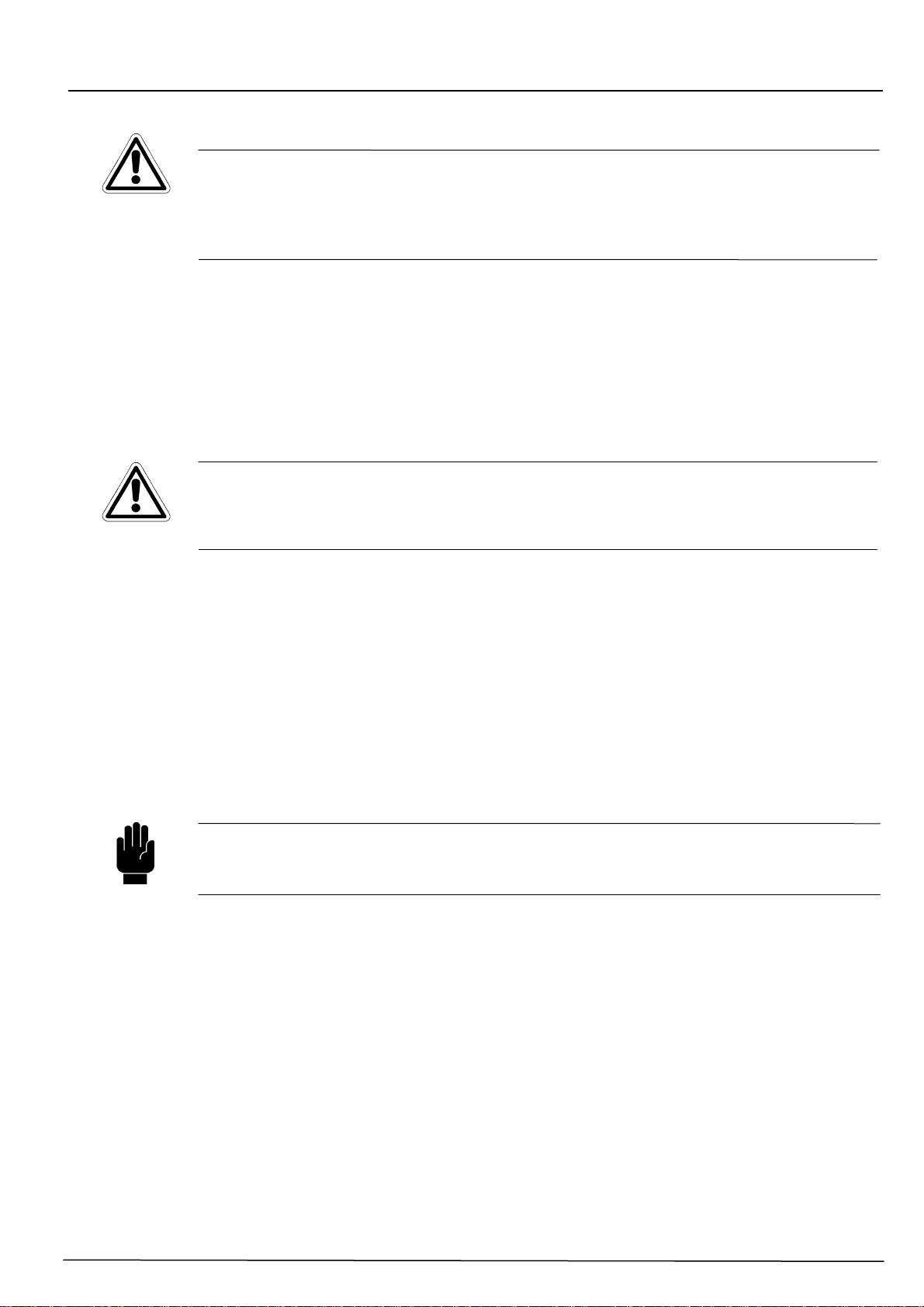
CAUTION
Caution messages appear in the manual in correspondence to the
description of procedures or operations that, if carried out incorrectly, may
cause damages to the operator or users.
MANUAL
This symbol on the instrument label, forces the operator to read the manual
carefully in all its parts, before and during the installation and use of the
device / instrument
1.2 DECLARATION OF RESPONSIBILITY BY THE MANUFACTURER
CHEMITEC will be held responsible for the safety, reliability and performance of the
equipment only if used in compliance with the following conditions:
•Calibration, modifications or repairs must be carried out by qualified personnel,
specifically authorised by CHEMITEC.
•Opening of the equipment and access to its internal parts may only be carried out by
personnel qualified for maintenance and specifically authorised by CHEMITEC.
•The environment in which the equipment is used must comply with safety regulations.
•The electrical connections of the environment must be carried out according to
regulations and must be perfectly efficient.
•Replacements that can be carried out on parts of the equipment and accessories must
be done so with others of the same kind and of the same characteristics.
•The use and maintenance of the equipment and of relative accessories must be
carried out in compliance with the instructions indicated in this manual.
•This manual must always be kept integral and legible in all parts.
1.3 LIMITS OF USE AND PRECAUTIONS FOR SAFETY
In order to guarantee safety of the operator together with the correct functioning of the
equipment, it is important to work within the limits permitted and to adopt all of the
precautions listed below: CAUTION
Check before use to make sure that all safety requirements are fully
satisfied. The equipment must not be powered or connected to other
equipment until safety conditions are satisfied.
1.3.1 ELECTRICAL SAFETY
CAUTION
All of the connections on the are isolated from the environment ground
(mass is not isolated).
DO NOT connect any of these connections to earth.

50 Series 8P
MULTIPARAMETER PLUG & PLAY ANALYZER
TECHNICAL MANUAL P/N XXX-0000 Rev.4 Ver.1.1
3
In order to guarantee conditions of utmost safety for the operator, we recommend that all
of the indications listed in this manual are respected.
•Power the equipment exclusively using network tension according to
specifications (100 ÷ 240 Vac/dc 50-60 Hz)
•Replace damaged parts immediately. Cables, connectors, accessories or other
parts of the equipment that may be damaged or not working correctly must be
replaced immediately. In this case contact your nearest authorised technical
assistance centre.
•Only use accessories and peripheries specified by CHEMITEC. In order to
guarantee all of the safety requirements, it is important to make exclusive use of the
accessories specified in this manual which have been tested in combination with the
equipment. The use of accessories and consumption materials of other
manufacturers or not specifically recommended by CHEMITEC will not guarantee the
safety and correct operation of the equipment. Only use peripherals that comply with
the regulations of their specific categories.
•According to UL, not connect to relay outputs a voltage exceeding 115V
1.3.2 SAFETY OF THE OPERATIVE ENVIRONMENT
•The panel of the 50 Series device is protected against the introduction of liquids.
Avoid subject the equipment to the risk of dripping water, sprays of water or immersion
in water and the use in environments in which such risks may be present. Equipment
in which liquids may have accidentally penetrated must be immediately switched off,
cleaned and controlled by authorised and qualified personnel.
•Protection.
50 Series Wall mounting
−IP66 EN60529
−EMI /RFI CEI EN55011 - 05/99
−CLASS II INSTRUMENT REQUIRES NO GROUND CONNECTIONS
•Use the equipment within the environmental limits of temperature, humidity and
pressure specified. The instrument has been developed to operate in the following
environmental conditions:
−Temperature of the working environment -20°C ÷ +65°C
−Temperature of storage and transportation -25°C ÷ +65°C
−Relative humidity 10% ÷ 95%RH – not condensing
CAUTION
The water treatment plant in which the instrument is introduced must be
developed in accordance with the functional requirements imposed by
current legislation.
The apparatus must be inserted perfectly into the plant.
The parameters indicated on the analyser must comply with current
regulations. Any signals of faults to the device must be positioned in an
environment that is constantly controlled by operative personnel or plant
assistants. Non compliance with even just one of these conditions may lead
the “logics” of the device to operate in a potentially dangerous manner for
users of the service.
50 Series 8P
MULTIPARAMETER PLUG & PLAY ANALYZER
TECHNICAL MANUAL P/N XXX-0000 Rev.4 Ver.1.1
4
Therefore, we recommend that service personnel and/or maintenance
personnel operate with the utmost care, pointing out any changes to the
safety parameters immediately, in order to avoid the creation of any
potentially dangerous situations.
As the considerations indicated above cannot be controlled by the product
in question, the manufacturer will not be held responsible for any damages
that these malfunctions may cause to people or things.
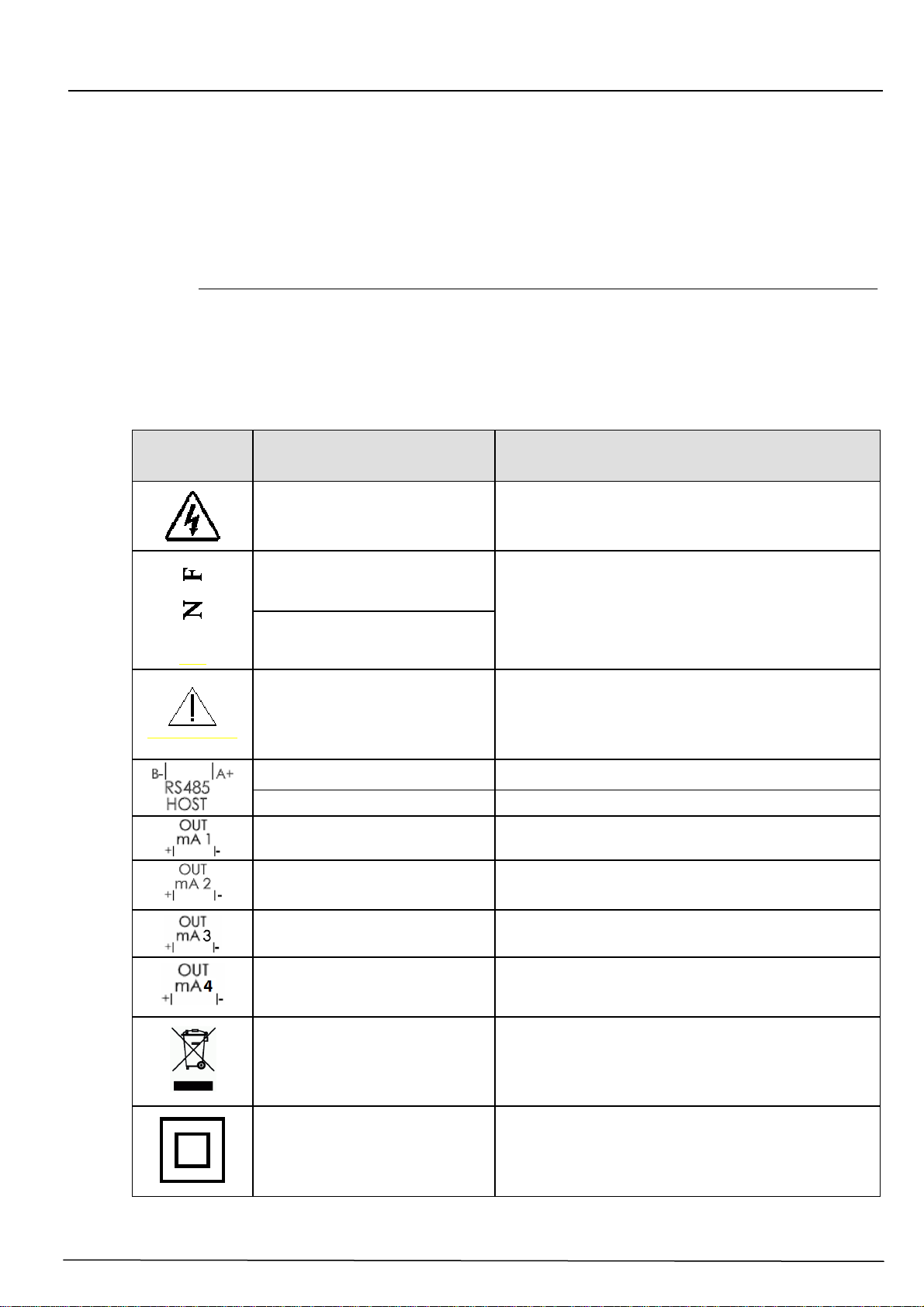
1.4 GRAPHIC SYMBOLS
The following table illustrates the drawings, the relative description and the position of all
graphic symbols present on the equipment panels and on any other equipment or external
devices to which they may be connected.
SYMBOL DESCRIPTION POSITION
Danger symbol A symbol located close to the clamps for
connection to power.
Phase
Symbols located close to the connections of
the equipment to the electricity network
Neutral
Caution! Refer to the
documentation attached A symbol located close to the points in which
the user manual should be consulted for
important information. (see paragraph
CAUTION).
Positive POSITIVE pole of the connector RS485 (A+)
Negative NEGATIVE pole of the connector RS485 (B-)
Analogical output n.1 0/4 ÷20mA separated galvanically
Analogical output n. 2 0/4 ÷20mA separated galvanically
Analogical output n. 3 0/4 ÷20mA separated galvanically
Analogical output n. 4 0/4 ÷20mA separated galvanically
Symbol of separate
collection of electrical
and electronic
equipment.
Symbol placed on the top of the electronic
box
Symbol of double electric
insulation This symbol indicates that the instrument is
built in insulation class II. So it does not need
to be grounded.
50 Series 8P
MULTIPARAMETER PLUG & PLAY ANALYZER
TECHNICAL MANUAL P/N XXX-0000 Rev.4 Ver.1.1
5
1.5 CAUTION SYMBOL
The symbol illustrated below represents the CAUTION symbol and reminds the operator
that he should read the user manual for important information, advice and suggestions for
the correct and safe use of the equipment.
This symbol is also used within the software, in particular in the “measures” screen,
putting attention to an event which will be explained in the following page of the screen.
In particular, when it is positioned close to connection points to cables and peripheries, the
symbol in question refers to careful reading of the user manual for instructions related to
the nature of such cables and peripheries and the methods for correct and safe
connections.
For the position of the CAUTION symbols on the equipment, refer to Chapter 2
“Commands and Indicators, Connections” and Chapter 3 “Installation” of this user manual.
The reproductions of equipment panels, with relative commands, connections, symbols
and labels are provided in this chapter. Each caution symbol is accompanied by a detailed
explanation of its meaning.
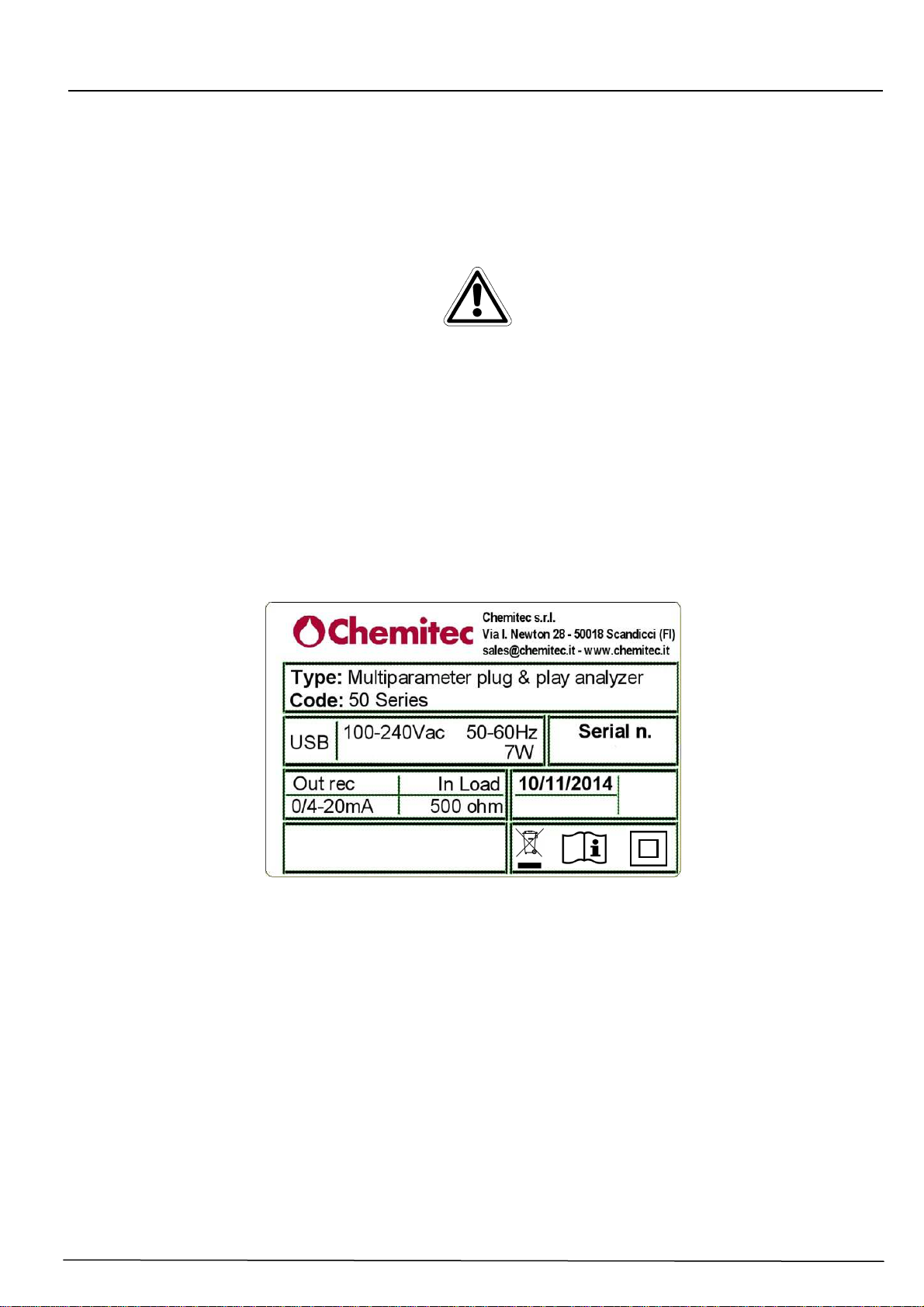
1.6 PLATE DETAILS
1.7 INFORMATION ON RECYCLING AND USE OF MATERIALS
CHEMITEC, in accordance with specific European regulations, aims at constant
improvement of development and of production procedures of its equipment with the
objective of drastically reducing the negative impact on the environment caused by parts,
components, consumption materials, packaging and the equipment itself at the end of its
life cycle.
Packaging is conceived and produced to allow for its re-use or recovery, including
recycling of the majority of the materials and to reduce the amount of waste or residues to
be disposed of, to a very minimum. In order to assure a correct environmental impact the
equipment has been designed with the smallest circuit possible, with the lowest
differentiation possible of materials and components, with a selection of substances that
guarantee utmost recycling and maximum reuse of the parts and waste disposal free from
ecological risks.
IP66

50 Series 8P
MULTIPARAMETER PLUG & PLAY ANALYZER
TECHNICAL MANUAL P/N XXX-0000 Rev.4 Ver.1.1
6
The equipment is made in such a way as to guarantee the easy separation or dismantling
of the materials containing contaminants compared with others, in particular during
maintenance operations and the replacement of parts.
CAUTION
The disposal/recycling of packaging, of consumption materials and of the
equipment itself at the end of its life cycle must be carried out in accordance
with the norms and regulations that are currently valid in the country in
which the equipment is used.
1.7.1 SPECIAL ATTENTION TO CRITICAL COMPONENTS
The instrument is fitted with an LCD liquid crystal display, which contains small amounts of
toxic materials.
50 Series 8P
MULTIPARAMETER PLUG & PLAY ANALYZER
TECHNICAL MANUAL P/N XXX-0000 Rev.4 Ver.1.1
7
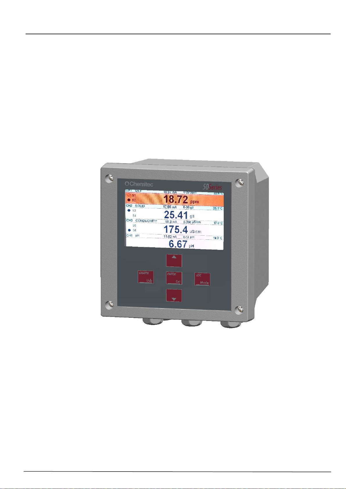
2 GENERAL DESCRIPTION
The analyser of this manual is made up of an electronic device plus a technical manual.
The device may be installed on a wall.
It is powered by the network (100-240Vac/dc-50/60Hz), 7W power consumption by a
Switching feeder.
This equipment has been designed to analyse ON-LINE and pilot the dosage pumps for
the treatment of water in different applications:
•Waste water treatment plant
•Treatment and Discharge of Industrial Water
•Fish farm
•Primary Water, Drinking Water
Figure 1 – Wall mounting Multiparameter analyzer (50 Series)
2.1 P ARAMETERS DETECTED BY THE INSTRUMENT
•MEASURING OF PH
•MEASURING OF ORP
•MEASURING OF INFRARED AND NEFELOMETRIC TURBIDITY
•MEASURING OF VISIBLE LIGHT LOW TURBIDITY S460LR
•MEASURING OF SUSPENDED SOLIDS
•MEASURING OF DISSOLVED OXYGEN
•MEASURING OF AMMONIA
•MEASURING OF NITRATES
•MEASURING OF CHLORINE, CHLORINE DIOXYDE, OZONE, CHLORITE, PAA
•MEASURING OF CONDUCTIVE AND INDUCTIVE CONDUCTIVITY
•CUSTOMIZABLE 4-20mA MEASURE

50 Series 8P
MULTIPARAMETER PLUG & PLAY ANALYZER
TECHNICAL MANUAL P/N XXX-0000 Rev.4 Ver.1.1
8
2.2 MAIN CHARACTHERISTICS
•Up to four simultaneous digital measurements and a fifth analogue measure 4-20mA.
•Measuring of Temperature using the PT100/PT1000 probe
•Programming key pad with 5 keys
•"CAL" Function Key to direct access to the calibration menu
•"GRAPH" Function Key to direct access to the graphs of measure
•“USB” Function Key for data download on USB support
•“MODE” Function Key for self-recognition probes
•LCD Graphic display 480x272 pixels, 4,3”
•Internal Data Logger (flash 32 Mbit) with the possibility of graphic and table visualisation
of measurement trends
•PID adjustment
•Serial outlet RS485 MOD BUS RTU
•Data download on USB support
•4 Programmable Analogical Outlets (with two equal measures the 3rd output can be set
as average)
•4 Relay Outlets for intervention thresholds
•1 Relay Outlet for Instrument Anomaly Alarm
•1 Relay Outlet for Probe Washing or Temperature Set Point
•1 Digital Inlet for disabling of doses
•1 Digital Inlet for washing start
Main hardware characteristics of the electronic device
The hardware structure of this periphery is based on the adoption of extremely new CPU
CMOS with 8 bits developed specifically for the execution of the so-called “embedded”
applications.
The card uses an EEPROM to store the Set-up data and flash memories for storage of the
archives of historical data and LOG files of events.
The Card has 1 RS485 gate (opto-isolated) for local networks used for connections with
local communication devices (configuration computer, terminals and remote controls etc).
The card integrates a Real Time Clock (clock with date) that allows the software to storage
figures in a chronological order.
The device has been designed to be fitted onto a panel, and is built with an IP66
protection enclosure.
2.2.1 TECHNICAL CHARACTERISTICS FOR DISSOLVED OXYGEN
The technical characteristics of the Analyser are listed in the following Table:
Measurement range 0.00 ÷ 20.00 ppm O2
0.00 ÷ 20.00 mg/L
000 ÷ 200 % SAT O2
2.2.2 TECHNICAL CHARACTERISTICS FOR PH MEASURING
Measurement range 00.00 ÷ 14.00pH
2.2.3 TECHNICAL CHARACTERISTICS FOR REDOX MEASURING
Measurement range ± 1500mV

50 Series 8P
MULTIPARAMETER PLUG & PLAY ANALYZER
TECHNICAL MANUAL P/N XXX-0000 Rev.4 Ver.1.1
9
2.2.4 TECHNICAL CHARACTERISTICS FOR TURBIDITY AND SUSPENDED SOLIDS
Due to the connected probe:
Digital Probe Measuring Range / Measuring
Unit
S461LT 0.00÷10.00 / 000.00÷100.00 NTU
S461T 0 ÷ 4 NTU
0 ÷ 40 NTU
0 ÷ 400 NTU
0 ÷ 4000 NTU
S461S 0.00÷ 30.00 g/L
S461T Accuracy ± 2% F.S.
S461S Accuracy ± 3% F.S.
2.2.5 TECHNICAL CHARACTERISTICS FOR NEFELOMETRIC TURBIDITY MEASURE
Turbidity 0.00÷10.00 / 000.0÷100.0 / 0000÷1000 NTU
2.2.6 TECHNICAL CHARACTERISTICS FOR ULTRA-LOW TURBIDITY MEASURE
Turbidity 0.00÷10.00 / 000.0÷100.0 / 0000÷1000 NTU
2.2.7 TECHNICAL CHARACTERISTICS FOR NH4+ MEASURING
Measurement range 0÷ 100ppm
2.2.8 TECHNICAL CHARACTERISTICS FOR NO3MEASURING
Measurement range 0÷ 100ppm
2.2.9 TECHNICAL CHARACTERISTICS FOR CL2, CLO2, O3, PAA, CL MEASURING
Measurement range 00.00 ÷ 2.00 / 5.00 / 10,00 / 20,00ppm
2.2.10 TECHNICAL CHARACTERISTICS FOR CONDUCTIVE CONDUCTIVITY MEASURING
Measurement range 0.00 ÷ 20.00µS
0.00 ÷ 200µS
000 ÷ 2000µS
000 ÷ 20000µS
Integrated NTC Temperature
2.2.11 TECHNICAL CHARACTERISTICS FOR INDUCTIVE CONDUCTIVITY MEASURING
Measurement range 000 ÷ 2000µS
000 ÷ 20000µS
000 ÷ 100mS
Integrated NTC Temperature

50 Series 8P
MULTIPARAMETER PLUG & PLAY ANALYZER
TECHNICAL MANUAL P/N XXX-0000 Rev.4 Ver.1.1
10
2.2.12 TECHNICAL CHARACTERISTICS FOR SECONDARY TEMPERATURE MEASURING
Sensor PT100/PT1000
Measurement range 0 ÷ +130°C
2.2.13 TECHNICAL CHARACTERISTICS FOR 4-20MA AUX INPUT MEASURING
Measurement range 4-20Ma
Freely programmable measure
2.2.14 OPERATING FEATURES
Power supply 100 ÷ 240 Vac/dc 50-60 Hz (optional 24 Vac/dc)
Power consumption 7W without probes
Relay outputs:
Set Point ON – OFF 0.00 ÷ 20.00 ppm O2 (for example )
0.0 ÷ 20.00 mg/L
000 ÷ 200 % SAT O2
ON – OFF Time 000 ÷ 999 Seconds
For every digital output a relay with contacts
opened normally is used. The maximum current
commutable is 1 Ampere, the maximum tension
commutable is 230Vac, maximum power 230VA
on a resistive load
Alarm:
Function Delay, Faults and Min./Max.
Delay time 00:00 ÷ 99:99 min
Threshold disabling Enable / Disable
Relay function Closed / Open
Holding range 0.0 ÷ 20.0 ppm ∆O2
0.0 ÷ 20.0 mg/L ∆O2
000 ÷ 200 % SAT ∆O2
Holding time 00:00÷ 99:99 min
For alarm end wash digital output, a relay with
contacts opened normally is used. The maximum
current commutable is 1 Ampere, the maximum
tension commutable is 230Vac, maximum power
230VA on a resistive load
Digital input:
Input voltage 24 Vcc /ac
Absorption 10mA max
Analogic outputs:
Outputs n.4 programmable outputs 0/4-20mA
Max. load 500 Ohm
NAMUR alarm output 2.4 mA (with range 4/20mA)
PID dosing function P – PI – PID
Proportional band 0 – 500%
Integration 0:00 – 5:00 min
Derivative 0:00 – 5:00 min

50 Series 8P
MULTIPARAMETER PLUG & PLAY ANALYZER
TECHNICAL MANUAL P/N XXX-0000 Rev.4 Ver.1.1
11
2.3 CONTROLS, INDICATORS AND CONNECTIONS
Figure 2 – Wall instrument, front panel
1. Visualizer with LCD Display
2. UP key
3. ESC key
4. ENTER key
5. DOWN key
6. GRAPH key
Figure 3 – Access to the terminal box
1
2
4
5
3
6
50 Series 8P
MULTIPARAMETER PLUG & PLAY ANALYZER
TECHNICAL MANUAL P/N XXX-0000 Rev.4 Ver.1.1
12
2.4 GRAPHIC DISPLAY
The graphic display allows for visualization of the various programming menus and, in the
measuring method (RUN), visualization of the measurements and of the state of
operation.
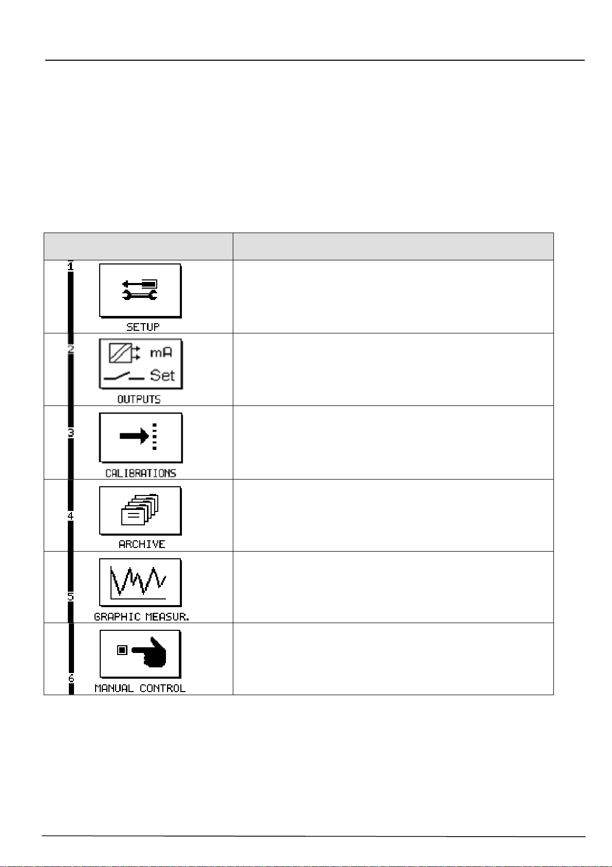
2.4.1 LIST OF PRIMARY MENUS
The following table illustrates the symbols visualized on the display which represent the
various programming menus.
VISUALIZATION
ON THE GRAPHIC DISPLAY DESCRIPTION
SETTINGS MENU
All basic parameters for operation logics are set
OUTPUTS MENU
Setting of analogical and digital outputs
CALIBRATIONS MENU
Calibration Procedure of the electrode
ARCHIVE MENU
Setting of the data archive and visualization mode
GRAPHICAL MEASUREMENT MENU
Visualization of archives in a graphical form
MANUAL CONTROL MENU
Manual control and activation of Inputs and Outputs
50 Series 8P
MULTIPARAMETER PLUG & PLAY ANALYZER
TECHNICAL MANUAL P/N XXX-0000 Rev.4 Ver.1.1
13
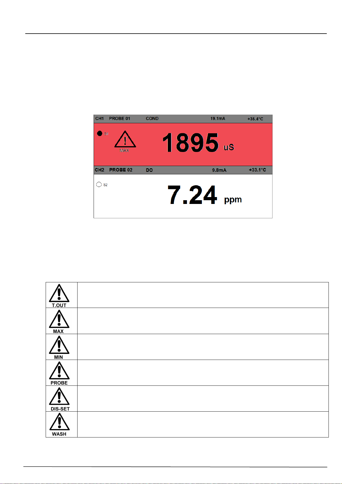
2.4.2 DIVISION OF THE GRAPHICAL DISPLAY INTO AREAS IN THE RUN METHOD
Each of the channels shows the value of the measurement, the state of the assigned relays,
the value of the current output and the possible temperature value. In addition, it is possible
to assign a name to each channel; this name can be edited by the user.
In case of failure, the area of the corresponding measure becomes red and shows the
symbol of attention with the reporting of the event that triggered the alarm. Below are shown
the types of possible alarms.
Figure 4 – Graphic display - divided up into areas
In the following table, for every area of the display indicated in figure 4, the symbols that
may appear during functioning of the device in a measurement method (RUN) are
represented and briefly described.
Time Out. This alarm appears in case you have programmed a time out of one
of the relays of a measure.
Out range max. Out range max. This alarm appears in case of exceeding the
maximum value read by the probe or programmed on the maximum logic set
point.
Out range min. Out range max. This alarm appears in case of exceeding the
maximum value read by the probe or programmed on the minimum logic set
point.
Probe Error. This alarm appears when a probe is not responding to serial
queries.
Dis-Set. This message appears when and the digital input is active and
programmed; this will disable the dosing, opening the relays and deactivating
the mA output.
Wash. This message appears in the case where a washing relay has been
programmed with its intervention intervals.

50 Series 8P
MULTIPARAMETER PLUG & PLAY ANALYZER
TECHNICAL MANUAL P/N XXX-0000 Rev.4 Ver.1.1
14
3 INSTALLATION
Although the unit is suitable for installation in outdoor environments, it is recommended to
avoid direct exposure to sun and weather. Before installing the 50 Series carefully read
the instructions provided below.
3.1 COMPOSITION OF THE SUPPLY
The supply consists of just one package which contains the following parts:
•1 electrical control and command panel PN ............?????
•1 Technical Manual PN ............?????
3.1.1 INSTALLATION OF WALL MOUNTED DEVICE
The wall must be completely smooth in order to allow for perfect adhesion of the device.
Figure 5 – Dimensions and encumbrance of the wall mounted device
Mechanical Dimensions 50 Series 8 Parameters
Dimensions (L x H x P) 144x144x122,5mm
Fixing depth 122,5mm
Material ABS Grey RAL 7045
Mounting Wall
Weigth 1 Kg
Frontal Panel Policarbonate UV Resistant
Open the instrument, open the pre-shaped holes and fix the instrument itself to the wall.
Use the provided plastic caps to close the holes.
The terminal box for connections is located on the bottom of the gear case and it is
necessary to keep it separated from other equipment by at least 15 cm. in order to make it
easier to use. Keep away from water drips and/or sprays of water from adjacent areas in
order to safeguard the instrument during programming or calibration stages.
50 Series 8P
MULTIPARAMETER PLUG & PLAY ANALYZER
TECHNICAL MANUAL P/N XXX-0000 Rev.4 Ver.1.1
15
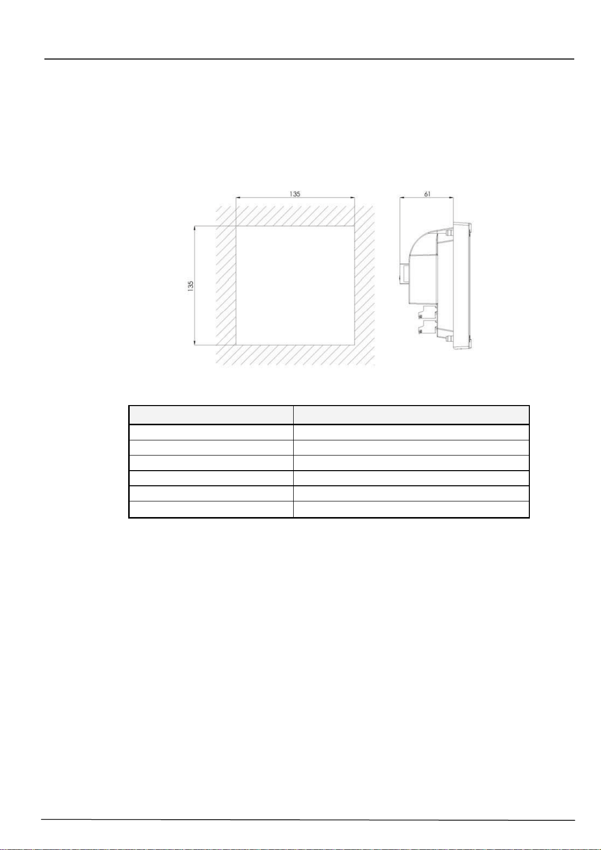
3.1.2 INSTALLATION OF 144X144 ELECTRICAL PANEL DEVICE
The wall must be perfectly smooth in order to allow for perfect adhesion of the electrical
panel close to the device.
The net depth of the panel must be at least 130 mm.
The thickness of the panel must not exceed 5 mm.
The perforation DIMA must comply with the following layout:
Figure 6 – Encumbrance and Dima for perforation of the panel
Mechanical Dimensions 4222 144x144 Panel Mounted
Dimensions (L x H x P) 144x144x86,5mm
Fixing depth 70mm
Material ABS Grey RAL 7045
Mounting Panel
Weight 0.7 Kg
Frontal Panel Policarbonate UV Resistant
The locking of the control unit to the panel is made through the mounting backplate, which
is fixed to the panel on the inner side, using the apposite screws.
3.1.3 CONNECTIONS TO THE POWER SUPPLY
If possible avoid any cables destined for high power use to be positioned close to the
device as they may cause faults of an inductive nature to the analogical section of the
instrument.
Apply a tension alternating between 100Vac and 240Vac 50/60 Hz or, according to
details on the identification plate, the most stabilised tension possible.
Avoid at all costs connections to power supplies that have been rebuilt, for example, with
the help of transformers in which this rebuilt power supply will feed other systems beyond
the device (perhaps of an inductive kind) because, in this way, high tension spikes will be
created and once they are irradiated it becomes very difficult to block and/or eliminate
them.
Connect the instrument to the power line by using a 2-pole cable with double PVC sheath,
copper section min 1mm2
50 Series 8P
MULTIPARAMETER PLUG & PLAY ANALYZER
TECHNICAL MANUAL P/N XXX-0000 Rev.4 Ver.1.1
16
CAUTION
The electric line must be fitted with a suitable life-saving device and
magneto-thermal, in compliance with correct installation norms.
The supply disconnecting device must be easily accessible after installing
the instrument and must be marked as the disconnection of the unit.
In any case it is always best to check the quality of the Ground connection. It is very
common to find Ground connections, mainly in industrial environments, that are
generators themselves of disturbances: in the case of any doubts on quality a connection
to a rod dedicated to the device plant is recommended.
3.1.3.1 Electrical Connections to the dosage systems (Users)
CAUTION
Before starting connections between the Device and the external Users,
make sure that the electrical panel is switched off and the cables from the
Users are not under tension.
“Users” mean the outlets and relays used in the device
−(SET1) for the Dosage Pump or control command
−(SET2) for the Dosage Pump or control command
−(SET3) for the Dosage Pump or control command
−(SET4) for the Dosage Pump or control command
−(SET5ALARM) the alarm command transmitted by the instrument to the siren
and/or flashing light
−(SET6WASH) electrode washing command
CAUTION
Each relay contact can support, on a resistive load, a maximum current of 1
Ampere with a max. of 230V, therefore a total power of 230VA
In the case of higher levels of power it is best to carry out connections as indicated in the
layout of fig. 6-b)
If the load to be handed is of low power or of a resistive nature, the layout indicated in Fig.
6-a) can be used.
Other manuals for 50 SERIES
1
Table of contents
Other Chemitec Measuring Instrument manuals


Popular Measuring Instrument manuals by other brands


McCrometer
McCrometer McMAG 2000 Quick start installation guide

Sennheiser
Sennheiser XSW IEM SR quick guide

LaserLiner
LaserLiner StarFinder quick start guide

Maxcom
Maxcom MXOPM26-50 Series Technical specification

aci
aci ACCESS series Assembly, installation and operation instructions

PCB Piezotronics
PCB Piezotronics 356A32 Installation and operating manual