Sonel MIC-5010 User manual


USER MANUAL
INSULATION RESISTANCE METERS
MIC-5010 and MIC-5005
SONEL S.A.
Wokulskiego 11
58-100 Świdnica
Version 1.11 27.07.2018

MIC-5010, MIC-5005 –USER MANUAL
2
MIC-5010 and MIC-5005 meters are modern, high-quality, easy and safe in operation. Please acquaint
yourself with the present manual in order to avoid measuring errors and prevent possible problems
related to operation of the meter.

MIC-5010, MIC-5005 –USER MANUAL
3
CONTENTS
1Safety ................................................................................................................4
2Meter Configuration.........................................................................................5
3Measurements..................................................................................................8
3.1 Measurement of insulation resistance...................................................................... 8
3.1.1 Double-lead measurement................................................................................................9
3.1.2 Three-lead measurement................................................................................................15
3.1.3 Measurements with increasing voltage - SV....................................................................16
3.1.4 Dielectric Discharge Indicator - DD..................................................................................19
3.2 Low-voltage measurement of resistance (MIC-5010 only)..................................... 20
3.2.1 Measurement of resistance of protective conductors and equipotential bonding with ±200
mA current......................................................................................................................20
3.2.2 Calibration of test leads...................................................................................................22
4Memory of measurement results .................................................................23
4.1 Storing the measurement results in the memory.................................................... 23
4.2 Viewing memory data............................................................................................. 25
4.3 Deleting memory data............................................................................................ 25
4.3.1 Deleting bank data..........................................................................................................26
4.3.2 Deleting the whole memory.............................................................................................27
5Data transmission..........................................................................................29
5.1 Set of accessories to connect the meter to a PC ................................................... 29
5.2 Data transmission through USB port...................................................................... 29
5.3 Data transmission with Bluetooth 4.2 module ........................................................ 29
6Software updates...........................................................................................31
7Power supply of the meter............................................................................32
7.1 Monitoring the power supply voltage...................................................................... 32
7.2 Battery power......................................................................................................... 32
7.3 Charging rechargeable battery............................................................................... 32
7.4 Mains power........................................................................................................... 33
7.5 General principles for using Li-Ion rechargeable batteries..................................... 33
7.6 General principles for using gel (lead) rechargeable batteries ............................... 34
8Cleaning and maintenance ...........................................................................35
9Storage............................................................................................................35
10 Dismantling and utilisation...........................................................................35
11 Technical specifications ...............................................................................36
11.1 Basic data .............................................................................................................. 36
11.2 Additional data ....................................................................................................... 38
11.2.1 Additional uncertainties according to IEC 61557-2 (RISO).................................................38
11.2.2 Additional uncertainties according to IEC 61557-4 (R ±200mA) ......................................38
12 Equipment ......................................................................................................39
12.1 Standard equipment............................................................................................... 39
12.2 Optional Equipment................................................................................................ 39
13 Manufacturer ..................................................................................................41

MIC-5010, MIC-5005 –USER MANUAL
4
1 Safety
The MIC-5010 and MIC-5005meters are designed for performing check tests of protection against
electric shock in mains systems. The meters are used for making measurements and providing results
to determine safety of electrical installations. Therefore, in order to provide conditions for correct oper-
ation and accuracy of obtained results, the following recommendations must be observed:
Before you proceed to operate the meter, acquaint yourself thoroughly with the present manual and
observe the safety regulations and specifications provided by the producer.
Any application that differs from those specified in the present manual may result in a damage to
the device and constitute a source of danger for the user.
The MIC-5010 and MIC-5005 meters must be operated only by appropriately qualified personnel
with relevant certificates authorising the personnel to perform works on electric systems. Operating
the meter by unauthorised personnel may result in damage to the device and constitute a source of
danger for the user.
During measurements of insulation resistance, dangerous voltage up to 5 kV occurs at the ends of
test leads of the meter.
Before themeasurement of insulation resistance you must be sure thattested object is disconnected
from the power supply.
During the measurement of insulation resistance do not disconnect test leads from the tested object
before the measurement is completed (see par. 3.1.1.); otherwise the capacitance of the object will
not be discharged, creating the risk of electric shock.
Using this manual does not exclude the need to comply with occupational health and safety regula-
tions and with other relevant fire regulations required during the performance of a particular type of
work. Before starting the work with the device in special environments, e.g. potentially fire-risk/ex-
plosive environment, it is necessary to consult it with the person responsible for health and safety.
It is unacceptable to operate:
a damaged meter which is completely or partially out of order,
a test leads with damaged insulation,
a meter stored for an excessive period of time in disadvantageous conditions (e.g. excessive
humidity). If the meter has been transferred from a cool to a warm environment with a high level
of relative humidity, do not start measurements until the meter is warmed up to the ambient
temperature (approximately 30 minutes).
One should remember that when the word appears on the display, it indicates insufficient
voltage of power supply and the need to recharge the batteries.
The symbols ErrX, where Xis a number between 0 to 9, indicate incorrect operation of the meter.
If after restarting the device this situation is repeated - it indicates that the meter is damaged.
Before measurement, choose a correct measurement function and make sure that test leads are
connected to respective measuring terminals.
Do not power the meter from sources other than those listed in this manual.
The RISO inputs of the meter are protected electronically from overload (e.g. due to having been
connected to a live circuit) up to 660V rms for 60 seconds.
Repairs may be performed only by an authorised service point.
Note:
Due to continuous development of the meter’s software, the actual appearance of the display,
in case of some of the functions, may slightly differ from the display presented in this oper-
ating manual.

MIC-5010, MIC-5005 –USER MANUAL
5
ATTENTION!
To display the correct battery discharge status, it is necessary to completely discharge and
then fully charge the battery, before starting the regular use of the meter.
Note:
An attempt to install drivers in 64-bit Windows 8 mayresult in displaying "Installation failed"
message.
Cause: Windows 8 by default blocks drivers without a digital signature.
Solution: Disable the driver signature enforcement in Windows.
2 Meter Configuration
Turn on the meter by pressing and
holding the MENU button.
The buttons and are used to set the
parameter value, while the and but-
tons move to the next parameter.
The setting sequence is as follows:
Rated grid frequency (50 Hz and 60 Hz).
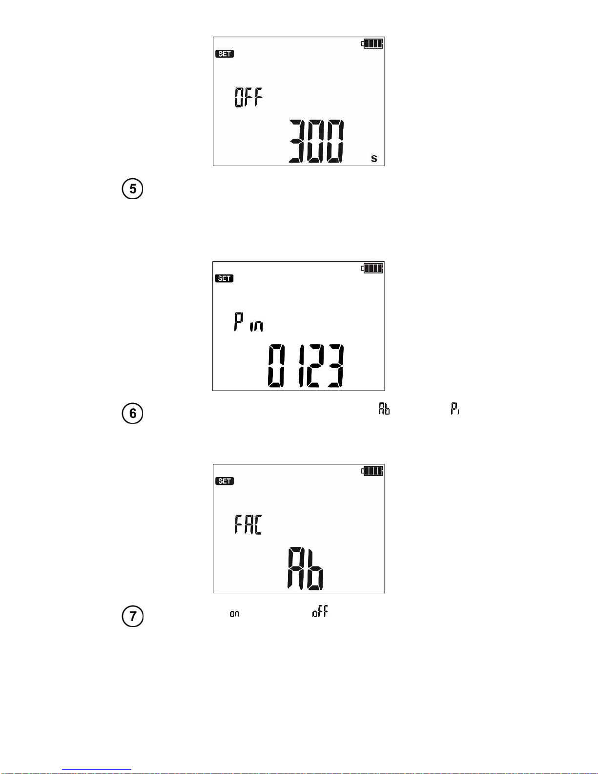
Auto-off time (300 s, 600 s, 900 s) or none (---).
MIC-5010, MIC-5005 –USER MANUAL
6
Pin, the digit being set is blinking. Moving to the next digit with
the F3 and F4 buttons.
The same code must be entered in the computer programme for wireless transmis-
sion. It is used to prevent access of unauthorized persons to the meter via wireless
connections (external entities).
Absorption coefficients for RISO: Ab1, Ab2 ( ) or PI, DAR ( ).
Each change sets the t1, t2 and t3 to their default values: for
Ab1/Ab2 t1=15s, t2=60, t3=0, and for PI/DAR t1=30, t2=60,
t3=0).
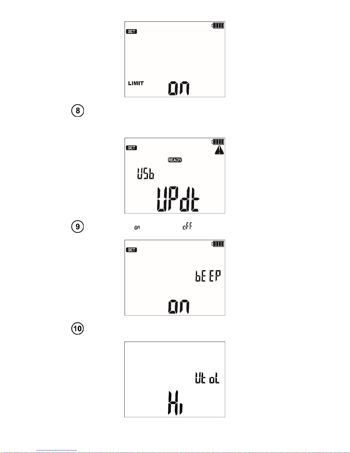
Enabling ( ) and disabling ( ) the limit settings (only MIC-
5010).
MIC-5010, MIC-5005 –USER MANUAL
7
Software updates.
This topic is discussed in paragraph 6.
Enabling ( ) and disabling ( ) the buzzer.
Test voltage accuracy: Hi –0…5%, Lo –0…10%
MIC-5010, MIC-5005 –USER MANUAL
8
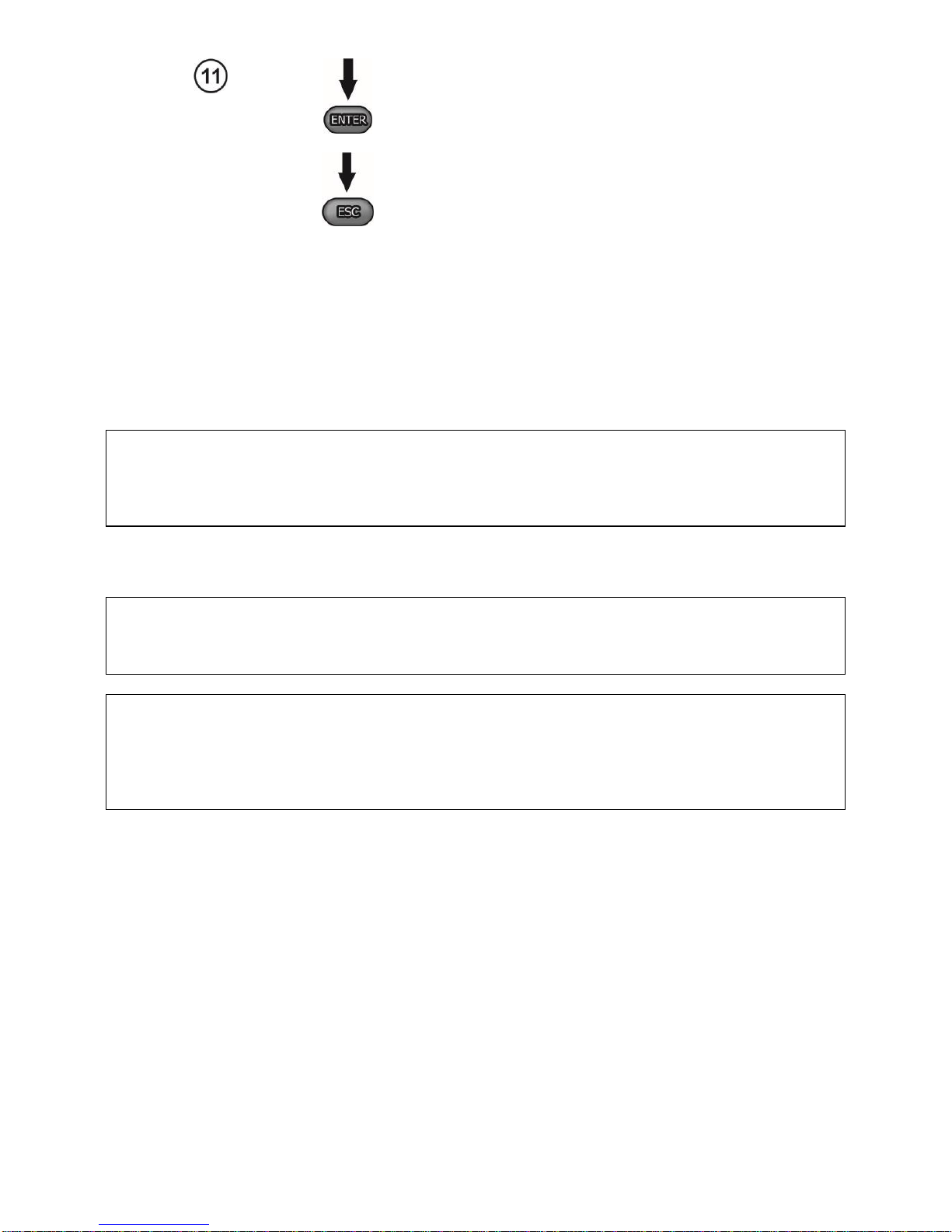
Press ENTER to confirm and go to the meas-
urement screen.
Press ESC to go to the measurement screen
without approving the changes.
3 Measurements
Notes:
- The result of the latest measurement is remembered by the meter until a next measurement is started
or the measuring function is changed by means of the rotary switch. It is displayed for 20 s. Then it may
be recalled by pressing ENTER, also after the meter is turned off and turned back on again.
WARNING:
During a measurement, switching of the range switch is forbidden because it may damage
the meter and pose a threat to the user.
3.1 Measurement of insulation resistance
WARNING:
The tested object must not be live.
Note:
During measurement, especially of high resistances, make sure that test leads do not touch
each other and probes (crocodile clips), because such a contact may cause the flow of sur-
face currents resulting in additional error in measurement results.
The converter output current is limited at a level of 1.2 mA or 3 mA. Activation of current restriction
is indicated with acontinuous audible signal. Themeasurement result is then correct, but thetest voltage
on the terminals is lower than the voltage selected before the test. Current limitation can happen in the
first stage of a measurement due to the object’s capacitance becoming charged.

MIC-5010, MIC-5005 –USER MANUAL
9
Actual measurement voltage as a function of the measured insulation resistance RX (for the
maximum measurement voltage)
3.1.1 Double-lead measurement
Set the rotary function selection
switch in one of the RISO positions, se-
lecting at the same time the measure-
ment voltage (positions 50 - 5000 V,
selected with a step of 10 V in the
range 50 V - 1 kV and with a step of
25 V between 1 kV and 5 kV). The
meter is in the voltage measurement
mode.
Press the MENU push-button to select time
used for calculating the absorption coeffi-
cients - (t1, t2, t3) and the whole measure-
ment time t, current IISO and limit (only MIC-
5010).
For the position of the selector between
50...5000 V, an additional option is available
to select the test voltage Un.
The buttons and are used to set the
parameter value, while the and but-
tons move to the next parameter.
MIC-5010, MIC-5005 –USER MANUAL
10
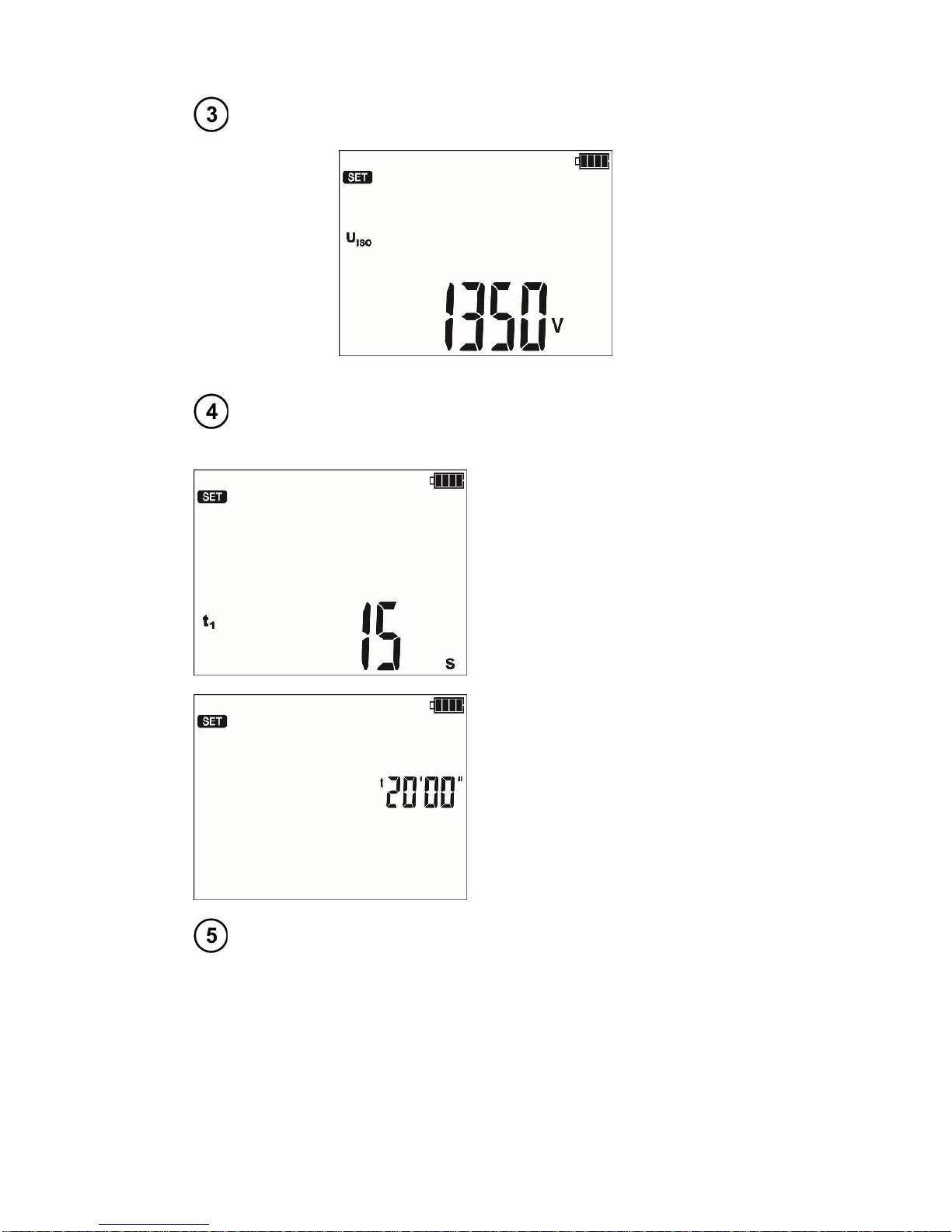
The setting sequence is as follows:
Test voltage Un,
times - in sequence t1 (1...600 s), t2 (1...600 s, but >t1) and t3
(1...600 s, but >t2) and t (independent of t1, t2 and t3: 1 s...99 min
59 s),
Setting of the times t1...t3.
Setting of the time t.
current IISO: 1,2 mA or 3 mA,

MIC-5010, MIC-5005 –USER MANUAL
11
limit (only MIC-5010).
For RISO the limit is the minimum value. The limit range is from 1 kΩto 15 TΩ.
The limit value is set using the and buttons. As the meter has many measurement sub-
ranges, an algorithm for rapid increase or decrease of values is implemented. When holding the value
key it changes very rapidly: first the hundreds, after 3 s tens, and after 3 s units etc. The limit setting is
circular. The resolution of the set limit is related to the sub-range.
To deactivate the limit (displayed symbol ---) press the button while in the 1 kΩposition or the
button while in the 15 TΩposition.
or
Press ENTER to confirm settings
(confirmed by beep) or press ESC to
exit without saving the changes.
Connect test leads according to the drawing.
MIC-5010, MIC-5005 –USER MANUAL
12
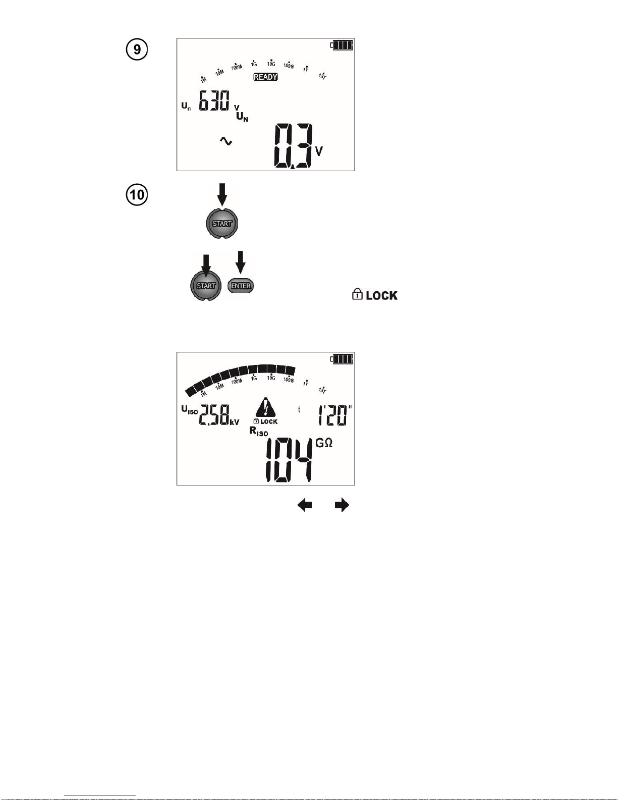
The meter is ready
for measurement.
Press and hold START push-button.
The measurement is performed continuously
until you release the button or the pre-set time
is reached.
In order to maintain (block) the measurement,
press ENTER while holding the START -
push-button pressed - the following symbol
will be displayed , then release the
button. In order to interrupt the measurement
in this mode, press START again or press
ESC.
View of the screen dur-
ing measurement.
During measurements controlled using the and buttons the display of the test current UISO
for the ILleacage current may be changed.
The meter is equipped with an advanced digital filter for result stabilisation in difficult and unstable
measurement conditions. When the F1 button is pressed before or during the measurement the meter
will make calculations which will stabilise the fluctuations of the measurement results. The meter dis-
plays a filtered value of measurements for a specified time period. The filter is selected by pressing the
F1 button i.e. after the first press the result shall be displayed as a filtered value from the last 10 s, after
the second press from the last 30 s, then for 60 s and finally the filter is turned off "- -". The filter setting
is circulating. The filter setting is erased automatically after the meter has been turned off or when the
measurement function is changed using the rotary selector.
The ability to set the filter depends on the set t measurement time, for example when t=20 s it is
only possible to set the filter for 10 s.

MIC-5010, MIC-5005 –USER MANUAL
13
After the measure-
ment is completed,
read the result.
Use the F3 and F4 buttons (SCREEN) to see indi-
vidual components of the result in the following or-
der:
RISO→ILand C→ Rt1 and It1→Rt2 and It2→Rt3
and It3→Ab1 (DAR)→Ab2(PI)→RISO, where C –is
the capacitance of the tested object.
Note:
During measurements of insulation resistance, dangerous voltage up to 5 kV occurs at the
ends of test leads of the meter.
It is forbidden to disconnect test leads before the measurement is completed. Failure to obey
the above instruction will lead to high voltage electric shock and make it impossible to dis-
charge the tested object.
- Disabling t2 will also disable t3.
- Timer measuring the measurement time is started when UISO voltage is stabilized.
- Symbol informs of an operation with limited inverter power. If this condition persists for 20
seconds, the measurement is interrupted.
- A short tone informs of passing 5 s periods of time. When the timer reaches characteristic points (tx
times), then for1 s a symbol (mnemonic) of this point is displayed which is accompanied bya long beep.

MIC-5010, MIC-5005 –USER MANUAL
14
- If any of the measured values of partial resistance is out of range, the value of the absorption coefficient
is not displayed –the display shows dashes.
- During the measurement a yellow LED is lit.
- After completion of measurement, the capacitance of the object tested is discharged by shorting RISO+
and RISO-terminals with resistance of 100 k.
- In case of power cables measure the insulation resistance between each conductor and other conduc-
tors shorted and grounded (figure below).
Additional information displayed by the meter
Test voltage is present on terminals of the meter.
Interference voltage lower than 50 V DC or 500 V AC, is pre-
sent on the tested object. Measurement is possible but may
be burdened with additional uncertainty.
Activation of current limit. The symbol displayed is accom-
panied by a continuous beep.
Breakdown of the tested object insulation, the measurement
is interrupted. The message appears after display-
ing for 20 s during the measurement, when the voltage pre-
viously reached the nominal value.
Un>50 V (for DC) or
Un~>500 V (for AC)
+two-tone, continu-
ous beep + and LED
lit in red
During themeasurement, AC voltage appeared or the object
cannot be discharged for 30 seconds. After 5 seconds the
meter returns to its default mode - voltmeter.

MIC-5010, MIC-5005 –USER MANUAL
15
3.1.2 Three-lead measurement
In order to eliminatethe influence of surface resistance in transformers, cables, etc. the three-
lead measurement is used, but do not connect the current measuring test lead RISO-to large ground
conductors. For example:
at the measurement of inter-winding resistance of a transformer, G socket of the meter should be
connected to the transformer tank;
when measuring the insulation resistance between one of the windings and the transformer’s tank,
connect G socket of the meter to the second winding:
G
MIC-5010, MIC-5005 –USER MANUAL
16
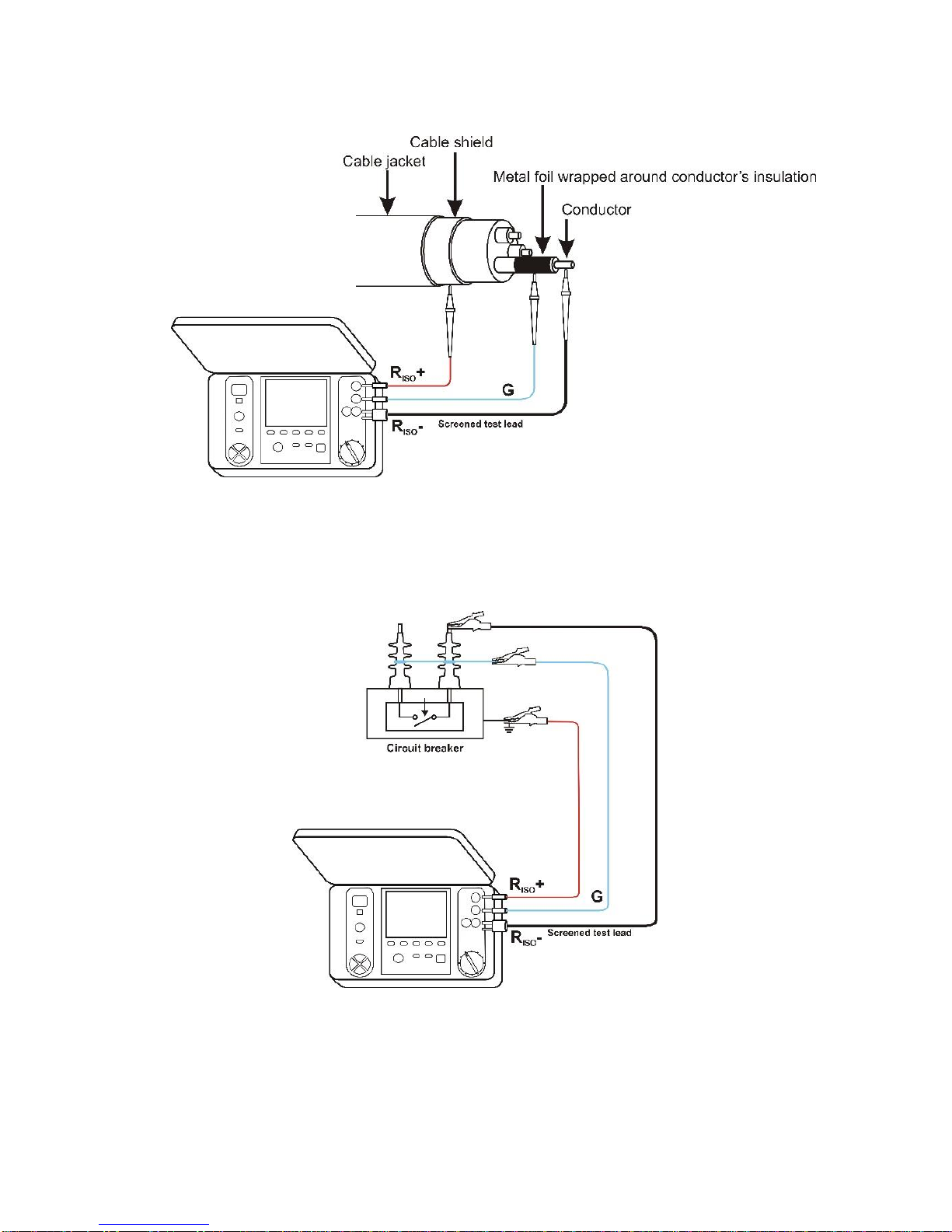
when measuring insulation resistance between one of the cable conductors and the cable shield,
the effect of surface resistances (important in difficult weather conditions) is eliminated by con-
necting a piece of metal foil insulating the tested conductor with Gsocket of the meter;
The same shall apply when measuring the resistance between two conductors of the cable, attaching
to Gterminal other conductors that do not take part in the measurement.
at themeasurement of insulation resistanceof a high voltage circuit breaker, Gsocket of the meter
should be connected to the terminals’ insulators of the breaker;
3.1.3 Measurements with increasing voltage - SV
In this mode the meter performs a series of 5 measurements with increasing voltage; the voltage
change depend on the set maximum voltage:
- 1 kV: 200 V, 400 V, 600 V, 800 V and 1000 V,
- 2.5 kV: 500 V, 1 kV, 1.5 kV, 2 kV and 2.5 kV,
Other manuals for MIC-5010
1
This manual suits for next models
3
Table of contents
Other Sonel Measuring Instrument manuals

Sonel
Sonel MIC-30 User manual

Sonel
Sonel CMP-1010 User manual

Sonel
Sonel MIC-15k1 User manual

Sonel
Sonel MIC-5001 User manual

Sonel
Sonel LXP-1 User manual

Sonel
Sonel CMP-1006 User manual

Sonel
Sonel MZC-310S User manual

Sonel
Sonel LMW-100 User manual

Sonel
Sonel MPI-536 User manual

Sonel
Sonel LXP-2 User manual


Popular Measuring Instrument manuals by other brands


Merck
Merck Spectroquant Picco COD/CSB manual

EasyGates
EasyGates GTE KMG-2000 System guide & installation

Unico
Unico S-2150 Series user manual

R&S
R&S ZNL Series Getting started

Michell Instruments
Michell Instruments Promet EExd Installation, operation & maintenance manual

Bender
Bender RCMB101 operating manual