abem Terraloc Pro 2 User manual

User Manual
Terraloc Pro 2
ABEM 20181009, based on release 3.0.4 of SeisTW

ABEM Terraloc Pro 2
Thank you for choosing ABEM Terraloc Pro 2
General information
Information in this manual is subject to change without notice and constitutes no commitment
by Guideline Geo AB.
Guideline Geo AB takes no responsibility for errors in this manual or problems that may arise
from the use of this material.
In general, e-mail correspondence gives the fastest response.
In view of our policy of progressive development, we reserve the right to alter specifications
without prior notice.
Guideline Geo will be pleased to receive occasional reports from you concerning the use and
experience of the equipment. We also welcome your comments on the contents and usefulness
of this manual. In all communication with Guideline Geo be sure to include the instrument types
and serial numbers.
Contact details:
Address:
Guideline Geo AB
Löfströms Allé 6A
SE-17266 Sundbyberg
Sweden
Phone:
+46 8 564 88 300
Web site:
www.guidelinegeo.com
Email:
© Copyright 2018 Guideline Geo AB. All rights reserved.

ABEM Terraloc Pro 2
i
Table of Contents
Section Page
About This Manual.....................................................................................................iii
1Get ready - Unpacking your new Terraloc® Pro 2............................................5
Welcome To Refraction, Reflection And Tomography.................................5
Features of the ABEM Terraloc Pro 2...........................................................5
The Delivered Instrument ..............................................................................6
Inspection.......................................................................................................7
Shipping Damage Claims ..............................................................................7
Shipping/Repacking instructions ...................................................................7
Registration....................................................................................................8
Take Time to Read The Technical Documentation.......................................8
Software.........................................................................................................8
2Overview of the Instrument................................................................................9
The Connector Panel......................................................................................9
The Power Panel ..........................................................................................11
The Built-in GPS Receiver ..........................................................................12
The User Interface Panel..............................................................................12
The Power Supply........................................................................................13
Interconnecting Two or More Instruments ..................................................14
3Quick Start .........................................................................................................15
4The User Interface .............................................................................................18
The Display..................................................................................................18
Keyboard and Mouse...................................................................................18
Using SeisTW..............................................................................................21
SeisTW Layout Parts ...................................................................................25
Menus...........................................................................................................36
Dialogs.........................................................................................................41
5Data Processing..................................................................................................73
Unfilter Data ................................................................................................73
First Breaks..................................................................................................73
FIR Filter......................................................................................................74
Cross Correlate.............................................................................................75
Moving Average ..........................................................................................77

ABEM Terraloc Pro 2
ii
6Triggering Methods ...........................................................................................79
Make/Break Switch Input ............................................................................79
Using the Trigger Coil.................................................................................79
Radio Triggering..........................................................................................79
7Measurement......................................................................................................80
Basic Operations..........................................................................................80
Data Transfer ...............................................................................................81
Optimizing ...................................................................................................82
8Troubleshotting and Diagnostics......................................................................84
General SeisTW Program Problems............................................................84
Data Acquisition Problems..........................................................................84
Trigger Problems .........................................................................................85
Remote Diagnostics (VPN)..........................................................................85
In Case of Malfunction ................................................................................87
9Appendix A. Technical Specification ...............................................................88
10 Appendix B. Connectors....................................................................................90
Seismic Input Connectors ............................................................................90
TTL Arm/Trig Connector ............................................................................92
11 Appendix C. The First Arrivals File Format (PCK) ......................................93
General.........................................................................................................93
Description...................................................................................................93
12 Appendix D. Seismic Methods..........................................................................94
Refraction.....................................................................................................94
Reflection.....................................................................................................94
Optimum Offset ...........................................................................................95
Tomography.................................................................................................95
VSP..............................................................................................................95
Vibroseis ......................................................................................................96
13 Appendix E. Bibliography.................................................................................97

ABEM Terraloc Pro 2
iii
About This Manual
The conventions and formats of this manual are described in the following paragraphs:
•Typographical conventions used in this manual:
Italic
Names of objects, figure descriptions
Bold
In-line minor headers, emphasis
Blue Italic
URL links
•Formats used in this manual for highlighting special messages:
―Use of the internal keyboard is given in this format
―A sequence of steps will have two or more of these parts
Further information about this particular usage is given like this
Note! This format is used to highlight information of
importance or special interest
Warning! Ignoring this type of notes might lead to loss of data or
a malfunction
These notes warn for things that can lead to people
or animals getting hurt or to equipment getting
damaged

ABEM Terraloc Pro 2
iv

ABEM Terraloc Pro 2
5
1 Get ready - Unpacking your new Terraloc® Pro 2
Welcome To Refraction, Reflection And Tomography
Welcome to the ABEM Terraloc® Pro 2, the multi-channel digital seismograph for
cost-effective refraction and high-resolution reflection surveys, tomography, vibration
measurements, and more, anywhere in the world in all weather conditions.
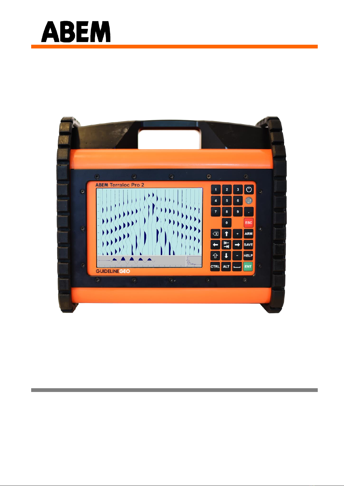
The basic Terraloc Pro 2 is a self-contained multi-channel seismograph with internal
PC-compatible computer, a hard disk and a daylight visible 8.4 “ TFT color display
with SVGA resolution. Operating power comes from two internal batteries, or any
external battery pack or power source that delivers from 10 - 28 volts DC. Typically
this means a re-chargeable battery pack, a car (or truck) battery, or AC/DC power
supply (office power supply unit). The inbuilt battery charger charges the internal
battery pack when an external power source is connected.
The Terraloc Pro 2 has a hard disk with a size of at least 100 GB. It also has 3 USB 2.0
ports and an Ethernet port.
The physical dimensions are the same for all models, 12 –48 Channels.
After a survey you may process data stored on the internal hard disk using Terraloc Pro
2 internal PC or an external computer. Large amounts of data can be transferred
between the Terraloc Pro 2 and an external PC using the built in Ethernet port in the
Terraloc Pro 2. For filteringand basic processing you can use the Terraloc Pro 2 internal
software called SeisTW, which is the softwarethat controls the functions of the Terraloc
Pro 2. Please ask your authorized Guideline Geo Distributor for details about the
seismic interpretation and processing packages that are available.
Your Terraloc Pro 2 was carefully checked at all stages of production. It was thoroughly
tested before being approved for delivery. If you handle and maintain it according to
the instructions in the technical documentation, you will get many years of satisfactory
service from it.
Features of the ABEM Terraloc Pro 2
Examples of features of the ABEM Terraloc Pro 2 are:
•SeisTW for Linux, Guideline Geo developed measurement software (Included and factory installed)
•3 USB ports for connecting external accessories such as USB CD/DVD, USB memory sticks,
keyboard, mouse, card reader etc.
•Ethernet port for fast transfers of data and networking capabilities
•Daylight visible color 8.4” TFT SVGA display
•Excellent resolution thanks to a 24 bit ADC (analog/digital converter)
•In-field quality control of measurements thanks to geophone tests, noise monitoring, and a wide
choice of single- or multi-trace view modes
•Excellent results for tomography and high resolution seismic thanks to selectable sampling rates
from 20 µs to 10 ms in nine steps
•Full on-screen display of recorded traces with software roll-along, automatic pick of first arrivals,
list of first arrival times, velocity calculation, frequency analysis of single traces.

ABEM Terraloc Pro 2
6
The Delivered Instrument
Your Terraloc Pro 2 arrives in a hard case transport box. Open it and unpack all items
carefully. Check the contents of the box or crate against the packing list. If you ordered
optional equipment, check the invoice/packing list for details and compare with your
original order.
A standard ABEM Terraloc Pro 2 system includes the following (Figure 1):
1 Terraloc Pro 2 field unit with a number of channels as shown on the packing list
1 External power cable with connector and crocodile clips
2 Internal battery pack
1 Office power supply unit
1 External USB-Keyboard-Mouse Kit
1 Trigger cable 250m on reel, (packed in own box)
1 Terraloc Pro 2 Accessories kit
1 Trigger coil
1 LAN cable RJ45 connectors 5m (for Ethernet)
1 Connection cable 2m, red
1 Connection cable 2m, black
1 USB memory stick
1 Warranty registration card

ABEM Terraloc Pro 2
7
Figure 1 Standard Terraloc Pro 2 system
Inspection
Inspect the instrument and accessories for loose connections and inspect the instrument
case for any damage that may have occurred due to rough handling during shipment.
The instrument is delivered in a reusable plywood box. The box is designed to offer a
convenient and safe transport option. All packing materials should be carefully
preserved for future re-shipment, should this become necessary. Always make sure to
use the transport box provided, or an alternative of at least equivalent mechanical
protection and shock absorption whenever the instrument is shipped.
Shipping Damage Claims
File any claim for shipping damage with the carrier immediately after discovery of the
damage and before the equipment is put into use. Forward a full report to Guideline
Geo, making certain to include the Guideline Geo delivery number, instrument type(s)
and serial number(s). If it is a question of short shipment you must make a claim in
writing to Guideline Geo within 14 days of your receipt of shipment.
Shipping/Repacking instructions
The Guideline Geo packing kit is specially designed forthe Terraloc Pro 2. The packing
kit should be used whenever shipping is necessary. If original packing materials are
unavailable, pack the instrument in a wooden box that is large enough to allow some
80 mm of shock absorbing material to be placed all around the instrument. This includes
top, bottom and all sides. Never use shredded fibers, paper or wood wool, as these
materials tend to pack down and permit the instrument to move inside its packing box.

ABEM Terraloc Pro 2
8
Please read our shipping instructions before returning instruments to Guideline
Geo. The instructions can be found on our website. For further assistance please
contact Guideline Geo or its authorized distributor. Contact information can be found
in the beginning of this document.
Registration
When you have checked the packing list, the next important thing to do is to register
your Terraloc Pro 2. To register send an email with your contact information to
[email protected]. Once registered, you will able to receive software updates
and product information.
Take Time to Read The Technical Documentation
To ensure you get optimum results with the ABEM Terraloc Pro 2, please take time to
read this instruction manual thoroughly. If you should, for any reason, have difficulties
in operating ABEM Terraloc Pro 2 or in getting satisfactory seismic survey results,
please contact your authorized Guideline Geo distributor. Guideline Geo always listens
to end-user comments about their experience with Guideline Geo products. So please
send occasional reports on field usage as well as your ideas on how the Terraloc Pro 2
and its technical documentation can be improved to help you do an even better job of
seismic surveying.
Software
Terraloc Pro 2 is delivered with all necessary software installed at the factory.
What is SeisTW?
SeisTW 3.0 and higher is a Linux application that is used to control the Terraloc Pro 2.
SeisTW is included and factory installed in all Terraloc Pro 2 instruments.

ABEM Terraloc Pro 2
9
2 Overview of the Instrument
The Connector Panel
All connectors except for the external power are situated on the right side panel of the
Terraloc Pro 2 (Figure 2). Some of the connectors are described in more detail in chapter
10 Appendix B. Connectors.
Note! Always have the connector protection dust caps in
place whenever a connector is not used
Figure 2 The Connector panel

ABEM Terraloc Pro 2
10
The connectors:
Label
Function
1
Ethernet
2
USB 1
3
USB 2
4
USB 3
5
TTL Trig/Arm: To connect two or more Terraloc Pro 2 as Master and
Slave(s), for radio shot, and vibrator hand-shaking.
Mating connector: see 10.2 TTL Arm/Trig Connector
6
Trigger input: for a trigger geophone shot instant contacts, a wire loop
around the explosive charge, or trigger output from a mechanical energy
source.
Mating connectors: 4 mm banana plug or bare wire
7
Reference channel 2: (up hole channel). Connector for a single
geophone or vibrator reference (signature).
Mating connectors: 4 mm banana plug or bare wire
8
Reference channel 1: (up hole channel). Connector for a single
geophone or vibrator reference (signature).
Mating connectors: 4 mm banana plug or bare wire
9
Signal: for connecting geophone spread cables to channel 13-24 (24-
channel) or 25-48 (48-channel).
The connector is wired to industry standard.
For wiring and mating connector: see chapter
10.1.1 for 12 and 24 Channel Terraloc Pro 2 and
10.1.2 for 48 Channel Terraloc Pro 2
10
Signal: for connecting geophone spread cables to channel 1-12 (24-
channel) or 1-24 (48-channel).
The connector is wired to industry standard.
For wiring and mating connector: see chapter
10.1.1 for 12 and 24 Channel Terraloc Pro 2 and
10.1.2 for 48 Channel Terraloc Pro 2

ABEM Terraloc Pro 2
11
The Power Panel
The power panel of the Terraloc Pro 2 is shown in Figure 3. The Power Input connector
is described in more detail in chapter 10 Appendix B. Connectors.
Figure 3 The Power panel
The connectors:
Label
Function
11
Power Input: for connecting an external power source.
Use External Power cable with clips for a car battery, or
Office power unit
12
Internal battery lid

ABEM Terraloc Pro 2
12
The Built-in GPS Receiver
Terraloc Pro 2 has a built-in GPS receiver (Figure 4). In order to function well the built-
in antenna in the handle of the instrument must be able to receive signals from a
sufficient number of satellites. This will normally not function indoors and in outdoor
areas with limited viewing angle towards the sky the function can be limited, for
example in a forest. Positioning data is automatically saved in the header of the current
record. The GPS receiver status is shown on the display (see chapter 4.4.7 Application
Status Bar).
Figure 4 The GPS antenna is integrated in the left side of the handle
The User Interface Panel
All interaction with the Terraloc Pro 2 is done through the user interface panel.
Figure 5 points out the parts of the user interface panel.

ABEM Terraloc Pro 2
13
Figure 5 The user interface panel
There are two LED’s shown through the LED Window:
-The green LED indicates disk activity
-The yellow LED indicates if sampling is on or off
The Power Supply
The Terraloc Pro 2 can use an external power source as well as internal batteries as
power supply. The external source can be a battery or a PSU (Power Supply Unit). If
possible use the supplied cable set for the external power source. Both external and
internal power sources can be attached at the same time. In this case the internal
batteries will be charged if the external battery is charged enough. The power supply
status is shown on the display (see chapter 4.4.7 Application Status Bar).
For field operations a good, adequate in capacity and recently charged battery is vital
for the best performance. It is possible to fully run the Terraloc Pro 2 without the
internal batteries but for your convenience you should always have at least one installed.
The internal batteries is primarily designed as a backup power source for operating the
instrument during set up, data transfer etc, hence it cannot be used alone to power the
instrument for a days work.
Once the instrument has been turned on and the external battery for any reason is
disconnected the instrument will automatically switch to the internal batteries. This
useful feature makes it possible to disconnect the external battery temporarily without
shutting off the instrument when for instance moving from one place to another.

ABEM Terraloc Pro 2
14
Interconnecting Two or More Instruments
Should more channels be needed than can be supplied by the use of a single instrument,
it is possible to connect (virtually) any number of Terraloc Pro 2 instruments. The Arm,
Disarm, and Trigger events can be synchronized with interconnected instruments. The
TTL Arm/Trig connector is used to connect the instruments, see chapter 10.2.
Figure 6 shows an example from a survey where four Terraloc Mk6 were used to
comprise a 96-channel system. The same can be done with Terraloc Pro 2 instruments.
Figure 6 96-channel record, made using four interconnected Terraloc Mk6

ABEM Terraloc Pro 2
15
3 Quick Start
In this section we will make a measurement of noise. It will give you an insight to how
easy it is to set your Terraloc Pro 2 up for operation. You will need no more equipment
than the instrument itself and the power supply. However, before starting any fieldwork
it is wise to invest time to go through and familiarize yourself with the various menus,
dialogs and options that exist. These are described in detail in the following chapters.
Should you feel uncertain during any of the steps below you can press <HLP> to get
access to the help screen for explanations about which key command does what.
Now follow these steps:
•Connect the power supply (see Figure 3 connector 11) and switch on the
instrument by pressing <POWER>
•Some diagnostic messages show up on the screen during the start up tests and
then Linux Lubuntu is started
•SeisTW starts automatically
•The Wizard mode will start by default
Figure 7 Wizard Mode start dialog
•Explanation to the user interface
opress <SPACE> to fold out drop down menus
opress <UP> or <DOWN> to highlight items in drop down menus
opress <ENT> to select items in drop down menus
opress <TAB> to move between options
opress <SPACE> to select items
opress <UP> or <DOWN> to increase or decrease number values

ABEM Terraloc Pro 2
16
•Change number of channels if needed
•Enter what type of measurement is to be performed.
•Enter the required record length
•Press <ENT> to select NEXT
Figure 8 Wizard Mode second dialog
•Enter geophone spacing
•Change direction of cables if needed
•Enter Trigger position if needed
•Enter Trigger position increment if needed
•Enter Energy source type if needed
•Press <ENT> to select OK
•The instrument will use recommended settings for selected measurement
•Press <ARM>. This arms the instrument and makes it ready to trigger and
record a trace. The status bar (at the bottom of the screen) displays the message
“<<<ARMED>>>”
•Press <CTRL> + <ARM> to force the instrument to trig. The message
"<<< TRIGGERED >>>" is displayed in the status bar, shortly followed by
“Transferring data…”, “Data in memory” and then “<<<ARMED>>>”.
•The recorded data is displayed in the three frames at the center of the screen. To
change view options, press <9>

ABEM Terraloc Pro 2
17
•Press <ENT> to accept the first stacking
•Trigging once more by pressing <CTRL> + <ARM> will replace the traces on
the screen with a new set that looks a little bit different. What you see now is the
average of the two measurements made so far
•Press <ENT> to accept the second stacking
•Press <SAVE> to save the data (the message “No data” will be displayed) or
press <ESC> to disarm the instrument (the message “Data in memory” will be
displayed)
•When you are finished getting acquainted with the instrument, you may shut it
down. Press <CTRL> + <SPACE> for the quick menu and select "Power Off"
among the menu items. Press <ENT> when the confirming dialog appears
•Now you should have learned a little about how to operate the instrument. Do
not be afraid to test different settings and modes. There is no risk of causing any
damage.

ABEM Terraloc Pro 2
18
4 The User Interface
The user interacts with the instrument through the User Interface Panel and possibly
connected USB input devices. This chapter explains the basics of this interaction.
The Display
SeisTW will normally be shown on the display. Figure 9 shows the main window,
which is shown if the Wizard mode or if a record is closed.
Figure 9 The SeisTW main window
For more information about the layout parts of SeisTW please see chapter 4.4.
Keyboard and Mouse
Commands from the user are entered through a keyboard and/or a mouse. There is a
built-in keyboard (see
Table of contents
Other abem Measuring Instrument manuals
Popular Measuring Instrument manuals by other brands

Kobold
Kobold KEC-2 operating instructions

Milkotester
Milkotester MASTER LM2-P2 operating instructions

Resol
Resol WMZ-G1 Manual for the specialised craftsman

PCB Piezotronics
PCB Piezotronics 1515-110-03A Installation and operating manual

GDS
GDS GDS-68XP Operation and maintenance manual

Johnson
Johnson 40-6705 Operator's manual

ENDEAVOUR
ENDEAVOUR ET0055A user manual

Pyxis
Pyxis ST-540SS-HR user manual

Ludlum Measurements
Ludlum Measurements 4525-7000 installation manual

Chauvin Arnoux
Chauvin Arnoux F605 user manual

DynAmp
DynAmp LKP Series Installation, operation and service manual

Elster Instromet
Elster Instromet RABO G65 instruction manual