NuAire LabGard NU-581-400E Manual

OM0255 Page 1 of 103
LabGard® ES HD Energy Saver
Class II, Laminar Flow
Biosafety Cabinet
Models
NU-581-400E/500E/600E
Console
Operation & Maintenance Manual
July, 2019
Revision 4
Series 1
Manufactured By:
NuAire, Inc.
2100 Fernbrook Lane
Plymouth, MN 55447
Toll-Free: 1-800-328-3352
In Minnesota: (763)-553-1270
Fax: (763)-553-0459
(400E & 600E ONLY)

OM0255 Page 2 of 103
July/2019
Congratulations!
You have just purchased one of the finest Laminar Flow Biosafety Cabinets available. With proper care, maintenance
(certification), and laboratory procedure, this cabinet will give you years of product and personnel protection from particulate
contaminants as prescribed in NSF/ANSI, EN 12469 and DIN 12980: 2016-10.Please read this manual carefully to familiarize yourself
with proper installation, maintenance and operation of the cabinet. Other reference and guideline materials are available through
the following web sites.
www.hc-sc.gc.ca
www.cdc.gov/od/ohs/
www.absa.org
www.absa-canada.org
www.ebsa.be
www.inspection.gc.ca
www.who.int
www.biosafety.be
www.hse.gov.uk
www.nsf.org
www.cetainternational.org
www.nuaire.com

OM0255 Page 3 of 103
July/2019
ABOUT THIS OPERATION & MAINTENANCE MANUAL
The information contained in this manual is intended to reflect our current production standard configuration model along with
the more frequently purchased options. Any unique additions/modifications/shop drawings are appended in the back flap of this
manual, along with any modifications and/or additions to procedures as outlined in this manual. A copy of the original factory test
report is also appended to this manual. In case this manual and/or test report is lost or misplaced, NuAire retains a copy in our files.
A replacement copy can be obtained by calling or writing NuAire, Inc. stating the model number and serial number and a brief
description of the information desired.

OM0255 Page 4 of 103
July/2019
LabGard® ES HD Energy Saver Class II, Laminar Flow Biosafety Cabinet
Models NU-581-400E/500E/600E Operation & Maintenance Manual
TABLE OF CONTENTS
Section No. 1.............................................................................. General Information
Section No. 2.............................................................................. Models & Features
Section No. 3.............................................................................. Warranty Disclaimer
Section No. 4.............................................................................. Shipments
Section No. 5.............................................................................. Installation Instructions
5.1..................................................................................... Location
5.2..................................................................................... Set-up Instructions
5.3..................................................................................... Testing Methods and Equipment
Section No. 6.............................................................................. Operating the NU-581E
6.1..................................................................................... Biosafety Cabinet Control
6.2..................................................................................... Operating Guidelines
6.3..................................................................................... Operating Sequence
6.4..................................................................................... Ergonomics
6.5..................................................................................... Cleaning Procedures
Section No. 7.............................................................................. General Maintenance
7.1..................................................................................... Decontamination
7.2..................................................................................... Fluorescent Lamp Bulb Replacement
7.3..................................................................................... Primary HEPA Prefilter Replacement
7.4..................................................................................... Secondary HEPA Filter/Motor Replacement
7.5..................................................................................... Sliding Window Replacement & Manual Adjustment
7.6..................................................................................... Airflow Control System Setup & Calibration
7.7..................................................................................... HEPA Filter Leak Tests
7.8..................................................................................... Airflow Smoke Pattern Test
7.9..................................................................................... Cleanliness Classification Test for Pharmacy Application
7.10................................................................................... Main Control Board Description & Replacement
7.11................................................................................... Digital Airflow Sensor Description & Replacement
Section No. 8..................................................................................... Error Messages, Troubleshooting, Option-Diagnostics &
Airflow Sensor Performance Verification
Section No. 9.............................................................................. Remote Contacts
Section No. 10............................................................................ Optional Equipment
10.1................................................................................... Ultraviolet Light
Section No. 11............................................................................ Electrical/Environmental Requirements
Section No. 12............................................................................ Disposal and Recycle
Insert.......................................................................................... Replacement Parts
MANUAL DRAWINGS
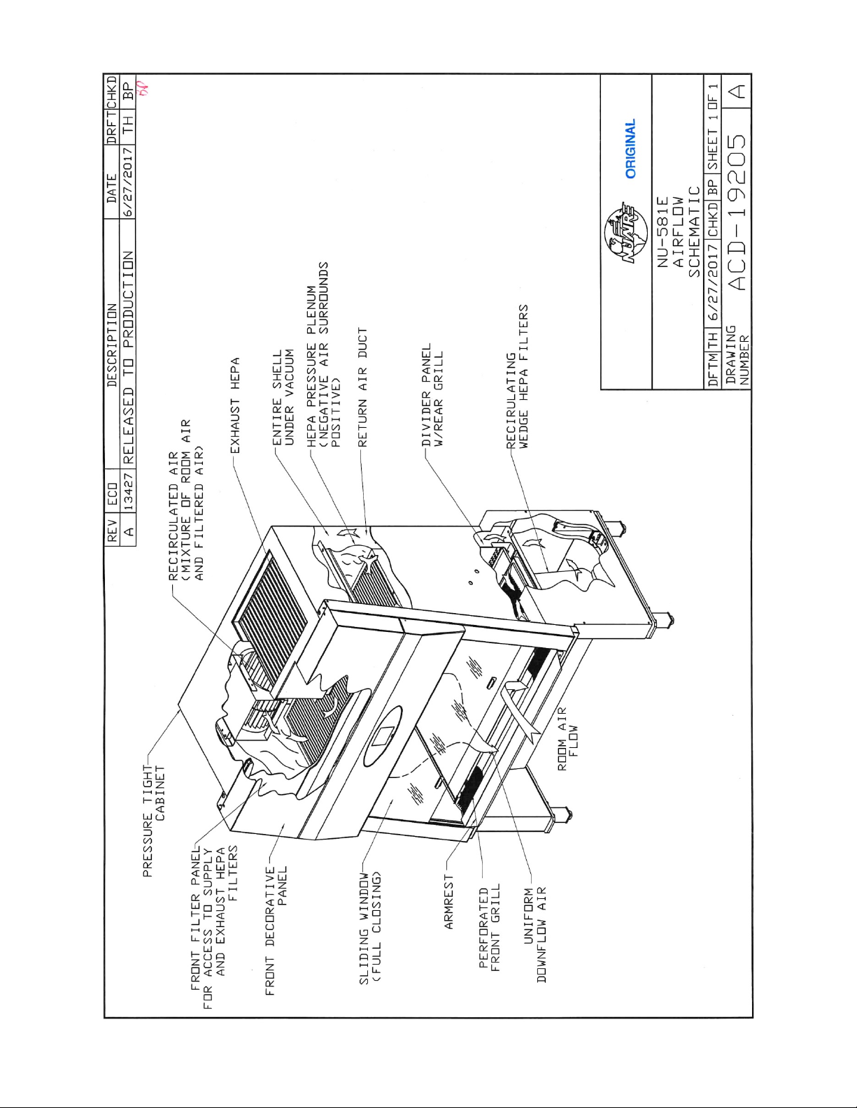
ACD-19205................................................................................. NU-581E Airflow Schematic
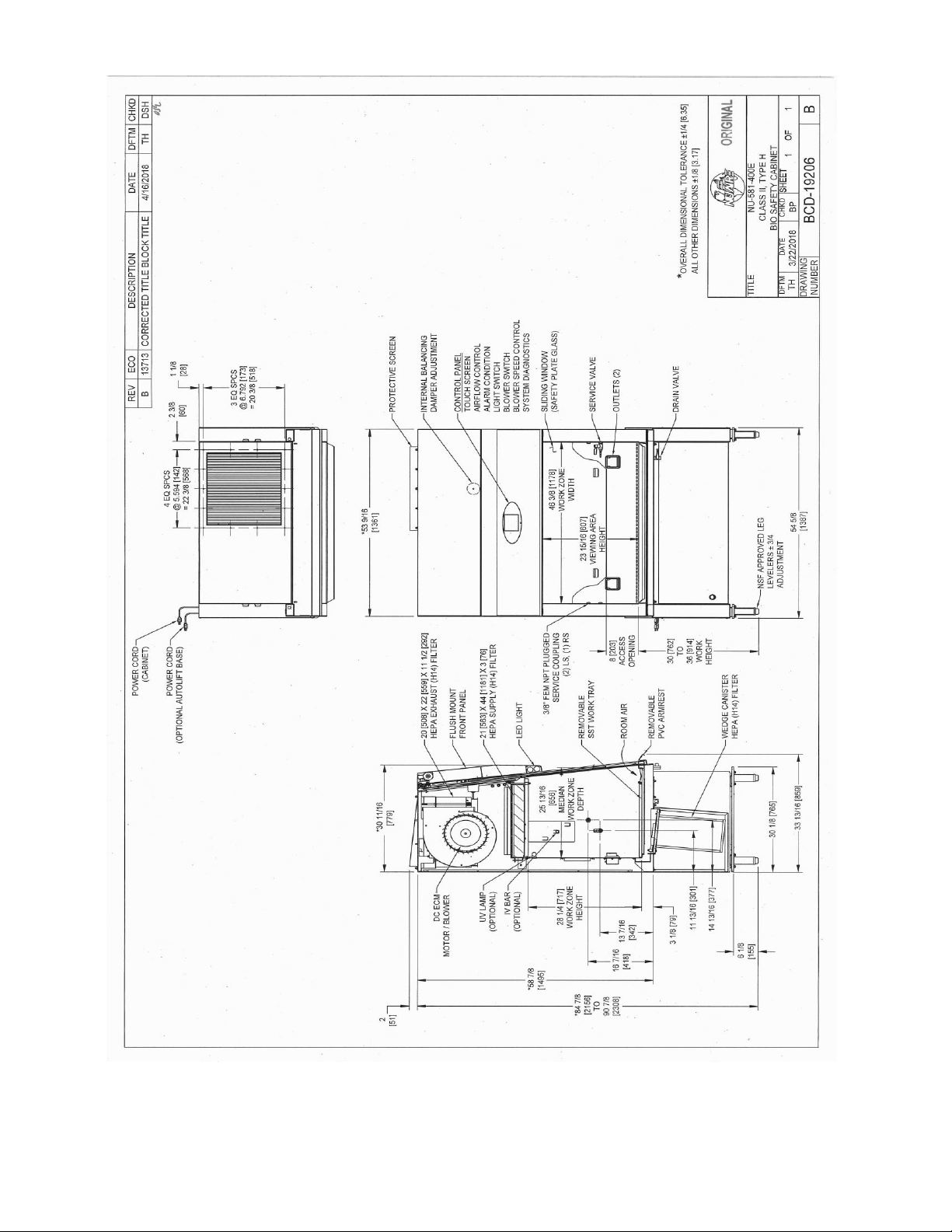
BCD-19206 ................................................................................. NU-581-400E Specification Drawing
BCD-19207 ................................................................................. NU-581-500E Specification Drawing
BCD-19208 ................................................................................. NU-581-600E Specification Drawing
BCD-19209 ................................................................................. NU-581E Security Drain Valve Installation
BCD-16509 ................................................................................. Auto Decontamination Setup
ASSEMBLY DRAWINGS
BCD-11817 ................................................................................. Control Center & Front Decorative Panel Assembly
BCD-11686 ................................................................................. Sliding Window Assembly & Adjustment
BCD-13923 ................................................................................. NU-581 Manual Base Adjustment
BCD-19210 ................................................................................. NU-581 Window Assembly Hinge Operation
BCD-12281 ................................................................................. Auto Window Switch/Cable Adjustment and Maintenance
BCD-12282 ................................................................................. Auto Window Cable and Window Assembly
ELECTRICAL SCHEMATICS
BCD-19211 ................................................................................. NU-581-400E/500E/600E Electrical Schematic

OM0255 Page 5 of 103
July/2019
LabGard® ES HD Energy Saver
Class II, Laminar Flow
Biosafety Cabinet
Models
NU-581-400E/500E/600E
MANUFACTURED BY:
NuAire, Inc. - Plymouth, Minnesota, U.S.A.
1.0 General Information
1.1 Description
The LABGARD® HD Model NU-581E Laminar Flow Biosafety Cabinet (LFBSC) is a console model, designed for the
preparation of Hazardous Drugs meeting the requirements of DIN 12980: 2016-10.The LABGARD® ES Model NU-581E
utilizes an Energy Saver DC ECM Motor optimally determined forward curved fan for each model size/width to maximize
both energy efficiency and filter loading capacity. The Energy Saver ECM Motor is controlled to airflow setpoints via a solid-
state DC motor controller with digital dual thermistor airflow sensors that provide an automatic compensation (constant
volume control) for both filter loading and line voltage variances.
The Laminar Flow Biosafety Cabinet, (LFBSC) is a product resulting from the development of the "laminar flow" principle
(see Airflow Schematic) and the application of environmental controls as required in the field of biological research or
chemical (hazardous drugs)containment. The LFBSC, when used with proper technique, is an effective primary engineering
control in obtaining the optimum product quality while reducing the potential for exposure of both product and personnel
to airborne biological or particulate chemical (hazardous drugs) agents in low to moderate risk-hazard research and drug
preparation or product operations, as prescribed by the Center for Disease Control (CDC) Atlanta, Georgia.
The NU-581E Console LFBSC meets the requirements of a Class II, since the cabinet conforms to the following requirements:
1. Maintains a minimum inflow velocity of 100 LFPM (.51mps) through the work access opening
2. Has HEPA filtered downflow air that is mixed with the inflow air from a common exhaust plenum
3. Discharges a percentage of air to the outside atmosphere after HEPA filtration
4. Has all biologically contaminated ducts and plenums under negative pressure or surrounded by negative pressure
Cabinets used for work with minute quantities of non-flammable or explosive volatile toxic chemicals and tracer amounts of
radionuclides required as an adjunct to microbiological studies must be exhausted through properly functioning exhaust
canopies.

OM0255 Page 6 of 103
July/2019
1.2 Safety Instructions
These safety instructions describe the safety features of the LABGARD® HD Model NU-581E LFBSC.
The safety cabinet has been manufactured using the latest technological developments and has been thoroughly tested
before delivery. However, the cabinet may present potential hazards if it is not installed and used as instructed for its
intended purpose or outside of operating parameters. Therefore, the following procedures must always be observed:
•The safety cabinet must be operated only by trained and authorized personnel.
•For any operation of this cabinet, the operator must prepare clear and concise written instructions for operating
and cleaning, utilizing applicable safety data sheets, plant hygiene guidelines, and technical regulations, in
particular.
owhich decontamination measures are to be applied for the cabinet and accessories
owhich protective measures apply while specific agents are used
owhich measures are to be taken in the case of an accident
•Repairs to the device must be carried out only by trained and authorized expert personnel.
•Keep these operating instructions close to the cabinet so that safety instructions and important information are
always accessible.
•Should you encounter problems that are not detailed adequately in the operating instructions, please contact your
NuAire Representative of NuAire technical Services.
1.3 Explanation of Symbols
CAUTION used without the safety alert symbol indicates a potentially
hazardous situation which, if not avoided, may result in property damage.
Potential electrical hazard, only qualified person to
Note: Used for important information.
Biohazard
Ground, Earth
CAUTION
Chemical Hazard
Flammable Hazard
Hazardous Gases!
Personal Protection Equipment Required.
Lead Free
Hazardous Drug
Safety alert symbol indicates a potentially hazardous situation
which, if not avoided, could result in death of serious injury.
Safety alert symbol indicates a potentially hazardous situation
which, if not avoided, may result in minor or moderate injury.
WARNING
!
CAUTION
!

OM0255 Page 7 of 103
July/2019

OM0255 Page 8 of 103
July/2019
2.0 Models & Features
The model NU-581E, LABGARD® ES HD Class II, Laminar Flow Biosafety Cabinet is manufactured in three sizes:
4ft. (1.2m), 5 ft. (1.5m), and 6 ft. (1.8m).

OM0255 Page 9 of 103
July/2019

OM0255 Page 10 of 103
July/2019

OM0255 Page 11 of 103
July/2019

OM0255 Page 12 of 103
July/2019
3.0 Warranty
Details regarding product warranties can be found in the published warranty data separate from this manual and included
within the data packet sent with the unit.
4.0 Shipments
NuAire takes every reasonable precaution to assure that your LABGARD® ES HD cabinet arrives without damage. Motor
carriers are carefully selected and shipping cartons have been specially designed to insure your purchase. However,
damage can occur in any shipment and the following outlines the steps you should take on receipt of a NuAire LABGARD®
ES HD cabinet to be sure that if damage has occurred, the proper claims and actions are taken immediately.
4.1 Damaged Shipments
4.1.1 Terms are factory, unless stated otherwise. Therefore, it is important to check each shipment before acceptance.
4.1.2 If there is visible damage, the material can be accepted after the driver makes a notation on the consignee's copy
of the freight bill. Then an inspection must be made to verify the claim against the carrier. This inspection is the
basis of your filing the claim against the carrier.
4.1.3 If concealed damage is found, it is absolutely necessary to NOTIFY THE FREIGHT AGENT AT ONCE, and request an
inspection. Without this inspection, the transportation company may not accept a claim for loss or damage. If the
carrier will not perform the inspection, an affidavit must be prepared stating that he was contacted on a certain
date and that he failed to comply with the request. This along with other papers in the customer's possession will
support the claim.

OM0255 Page 13 of 103
July/2019
5.0 Installation Instructions
5.1 Location
Within the laboratory, pharmacy, etc., the ideal location of the Biosafety cabinet is away from personnel traffic lanes, air
vents (in or out), doors and/or any other source of disruptive air currents.
SUGGESTED CABINET LOCATION IN LABORATORY
THE EXHAUST FILTER AREA IS ESPECIALLY SUSCEPTIBLE TO DISRUPTIVE AIR CURRENTS FROM AIR VENTS. The Electronic
Airflow Control System's exhaust sensor is located just above the exhaust HEPA filter and if disruptive air currents are
present, the exhaust sensor could be influenced by them, and indicate disruptive readings on the front panel display.
If drafts or other disruptive air currents exceed the inflow velocity of the cabinet through the access opening, the potential
exists for contaminated air to exit or enter the work zone area of the cabinet. It depends on the severity of the air current.
REMEMBER: A BIOSAFETY CABINET IS NO SUBSTITUTE FOR GOOD LABORATORY TECHNIQUE.
Where space permits, a clear 6" (152mm) area should be permitted on each side of the cabinet for maintenance purposes.
The electrical outlet into which the cabinet is connected should be readily accessible for maintenance purposes. Do not
position the cabinet to prevent access to the power cord. The power cord plug serves as the disconnect and should
remain readily accessible. If the outlet is inaccessible, such as a conduit (hardwired) connection, then an appropriate
warning label should be applied near the cabinets on/off switch to indicate the circuit breaker on the power distribution
panel should be used. A MINIMUM CLEARANCE OF 6" (152MM) IS REQUIRED FROM THE TOP OF THE CABINET TO THE
CEILING FOR PROPER VENTILATION OF THE EXHAUST EFFLUX.
If this cabinet is used in a pharmacy application, it is strongly recommended that the cabinet be exhausted to the outside.
In addition, if this cabinet is used in microbiological application with minute quantities of volatile toxic chemicals and tracer
amounts of radionuclides, Per CDC/NIH and NSF it is strongly recommended that the cabinet be exhausted to the outside.
NuAire offers a canopy type of exhaust transition, which will capture the exhaust efflux from the cabinet.
Canopy, Thimble or Air Gap Exhaust Transitions (with and without integral fan)
Note: THE EXHAUST SYSTEM SHOULD BE FITTED WITH A BACKDRAFT DAMPER TO PREVENT REVERSING OR
AIRFLOW IN THE SYSTEM.
NuAire strongly recommends a canopy or thimble exhaust for most applications.
See separate instruction sheets for a discussion of exhaust transitions and installation requirements
Note: Some countries (i.e. Germany) only allow canopy or thimble type transitions.
Verify requirements per Local, State and Federal code laws.

OM0255 Page 14 of 103
July/2019
5.2 Set-Up Instructions
Remove outer shipping protection (carton or crating). The cabinet is fastened to the base skid and it is usually the best
procedure to leave the skid in place until the cabinet is located in its approximate position to facilitate ease in handling. It
can then be removed from the skid by removing the banding, bolts and screws holding the cabinet to the skid. It may be
necessary to remove the Control Center in order to gain passage through a doorway. It can easily be removed by following
the instructions on drawing BCD-11817.
It is recommended that no less than two people are present using a
lifting system for placement of the cabinet onto the base stand.
It is not recommended to manually lift the cabinet onto the base stand
5.2.1 Manual Cabinet Height Adjustment (BCD-13923)
To manually adjust the height of the cabinet, remove the outside cover panels on the cabinet base. While
supporting the cabinet base loosen the bolts on the telescoping legs and remove them allowing the leg assembly
to freely move.Place at desired height and reattach bolts and cover panel. Only adjust one side at a time.
5.2.2 Leveling
Using a level placed on the work tray, adjust the leg levelers, first, end to end, then, front to back.
The NSF approved leg levelers provide a ±3/4" (20mm) adjustment.
5.2.3 SST Cap/Security Drain Valve Installation (BCD-19209)
The cabinet is supplied with a stainless steel (SST) cap installed. If the security drain valve is not desired or
allowed, leave the SST cap in place. If the security drain is desired, (NOTE: CHECK WITH YOUR SAFETY PERSONNEL
FOR REGULATORY REQUIREMENTS (.E. LOCKING TYPR) OF DRAIN VALVE INSTALLATION) remove the handle from
the valve stem with security tool provided to gain clearance for valve body rotation. Add Loctite 242 (furnished) to
the threads and rotate valve body until secure, with the valve stem (for handle) on the left side. Re-install handle
to valve stem.
5.2.4 Gas Service
NuAire doesn't recommend the use of natural gas within the BSC, but if gas service is determined to be necessary
for the application, appropriate safety measures must take place. All NuAire BSC's have precautionary warning
labels that say the following:
Use of explosive or flammable substances in this cabinet
should be evaluated by your appropriate safety personnel.
Once the determination has been made by the appropriate safety personnel, the application of natural gas must
be performed in accordance to national, state and local codes. IT IS ALSO STRONGLY RECOMMENDED THAT AN
EMERGENCY GAS SHUTOFF VALVE BE PLACED JUST OUTSIDE THE BSC ON THE GAS SUPPLY LINE.
The gas valve, when this option is installed, will only operate or flow gas when the cabinet blower is on and no
alarm is present. A solenoid valve is installed on the gas supply line for this purpose.
Note: Some countries (i.e. Germany) only allow certain types of certified valves to be used for natural gas
(i.e. Germany DVGW Certified). Verify requirements per Local, State and Federal codes/laws.
As previously stated NuAire doesn't recommend the use of natural gas within the BSC and ASSUMES NO
RESPONSIBILITY FOR ITS USE. USE AT YOUR OWN RISK. The Bunsen burner flame within the BSC not only
contributes to heat build-up; is also disrupts the laminar air stream, which must be maintained for maximum
efficiency. IF THE PROCEDURE DEMANDS USE OF A FLAME, A BUNSEN BURNER WITH ON DEMAND IGNITION IS
STRONGLY RECOMMENDED. DO NOT USE CONSTANT FLAME GAS BURNERS. During use, the Bunsen burner
should be placed to the rear of the workspace where resulting air turbulence will have a minimal effect.
CAUTION
!
CAUTION
!

OM0255 Page 15 of 103
July/2019

OM0255 Page 16 of 103
July/2019
5.2.5Plumbing Services
Service ball valves with the type of service specified by the removable button on the handle are located in the
work zone. The service ball valves are not recommended for pressure over 75 p.s.i. (5.2 BAR). Reducing valves
should be installed external to the cabinet if necessary. Service ball valves should never be used for flammable
gasses or oxygen service. A special needle valve for oxygen service or certified valve is required and available upon
request.
External connection is to 3/8 inch (10mm) NPT coupling in the inner sidewalls. Connection to plant utilities should
be made with proper materials for the individual service and according to national and/or local codes. Observe all
labels pertaining to the type of service and operating pressure.
5.2.6 Electrical Services
The NU-581E series Biosafety Cabinets may be "hardwired" (optional) or plugged into an outlet with protective
earthing connection with the standard power cord.The cabinet requires 230 VAC, 50/60 Hz, single phase (current
rating varies per cabinet size, reference Electrical/Environmental Requirements). It is recommended that power to
the cabinet whether hardwired or plug connected be on its own branch circuit, protected with a circuit breaker at
the distribution panel near the cabinet.
5.2.7 Final Assembly
Remove the protective cardboard cover over the exhaust HEPA filter, located under the protective screen if in
place. Attach the exhaust sensor shroud over the exhaust sensor. The shroud should be placed as close as
possible to the exhaust HEPA filter without coming in contact. The sensor gasket should be tightly against the
sensor shroud to prevent sneak airflow paths. The exterior surface and viewing glass are easily cleaned with any
mild household detergent cleaner using a soft cloth. Harsh chemicals, solvent-type cleaners and abrasive cleaners
should not be used.
Do not attempt to clean the HEPA filter media. Cabinet interior walls or work surface are easily cleaned with any
mild household detergent cleaner using a soft cloth. Turn the cabinet on and let it operate for 60 minutes before
using it as a LFBSC.

OM0255 Page 17 of 103
July/2019
5.3 Testing Methods and Equipment
After installation and prior to use, NuAire recommends that the cabinet be tested or commissioned to factory standards.
As part of testing, the certifier should go through the following initial checklist to assure all aspects of the BSC installation
are complete and ready for testing.
•Review product installation
- Exhaust connection, if present
- Damper valve installed correctly with label toward front, if present
- BSC basestand level
•Verify airflow sensor shroud is in place
- Downflow
- Exhaust flow
•Verify configuration type selection for specific model * (see section 7.6.2.1)
•Verify setpoints and alarm limits for specific model * (see section 7.6.2.1)
•Perform BSC installation tests
- At a minimum, the following tests should be performed, but not limited to:
•Primary and secondary HEPA filter leak tests
•Downflow velocity test with high/low alarm limits
•Inflow velocity test with high/low alarm limits
•Airflow smoke patterns
The testing methods and equipment required are specified in the general maintenance section and on the factory
inspection report included with this manual (see insert in back cover). As per DIN 12980: 2016-10, all installation,
commissioning, testing and maintenance actions are required to be documented. Use forms provided with cabinet (see
insert) to document the actions.
NOTE: IT IS RECOMMENDED THAT THESE TESTS BE PERFORMED BY A QUALIFIED TECHNICIAN WHO IS FAMILIAR
WITH THE METHODS AND PROCEDURES FOR TESTING BIOSAFETY CABINETS (SEE INSERT).
NOTE: AFTER THE INITIAL INSTALLATION TEST, NUAIRE RECOMMENDS THAT THE CABINET BE RETESTED AT A
MINIMUM ON AN ANNUAL BASIS AND AFTER EVERY FILTER CHANGE OR MAINTENANCE ACTION OR ANY TIME
THE OPERATOR FEELS IT IS NECESSARY.
Note that the LABGARD® ES HD cabinets, filters and seals provide premium performance; Quality Control in both design and
manufacturing assure superior reliability. However, protection to both product and operator is so vital that installation
testing to the performance requirements should be accomplished as stated to ensure Biosafety established by the factory
standards.

OM0255 Page 18 of 103
July/2019
LabGard® ES HD Energy Saver Class II
Laminar Flow Biosafety Cabinet
Models NU-581-400E/500E/600E
Catalog Number
Catalog Number
NU-581-400E
Nominal 4 foot (1.2m)
NU-581-500E
Nominal 5 foot (1.5m)
NU-581-600E
Nominal 6 foot (1.8m)
Performance Specifications
1. Personal Protection
2. Product Protection
NSF/ANSI 49
EN 12469
DIN 12980: 2016-10
NSF/ANSI 49
EN 12469
DIN 12980: 2016-10
NSF/ANSI 49
EN 12469
DIN 12980: 2016-10
EN 12469 Class
Class II
Class II
Class II
DIN 12980 Type
Type H
Type H
Type H
Style of Cabinet
Console
Console
Console
Cabinet Construction Pressure Tight Design
All welded stainless steel
16GA, Type 304
14 GA HRS Base
All welded stainless steel 16GA,
Type 304
14 GA HRS Base
All welded stainless steel 16GA,
Type 304
14 GA HRS Base
Diffuser for Air Supply (Metal)
Non-flammable
Non-flammable
Non-flammable
HEPA Filter Seal Type:
Supply Filter-99.995% Eff. On MPPS
Exhaust Filter-99.995% Eff. On MPPS
Wedge Prefilter-99.995% Eff. on MPPS
HEPEX Seal
Neoprene
Neoprene
HEPEX Seal
Neoprene
Neoprene
HEPEX Seal
Neoprene
Neoprene
Fumigation : Automated per EN 12469,
Annex J Procedure
Yes Yes Yes
Standard Services:
Service Coupling (3/8 inch NPT)
Gas Valve/Service Coupling (3/8inch NPT)
Outlet
One, Right Sidewall
One, Right Sidewall
Two, Backwall
One, Right Sidewall
One, Right Sidewall
Two, Backwall
One, Right Sidewall
One, Right Sidewall
Two, Backwall
Optional Services:
Gas Cocks 3/8" NPT
Ultraviolet Light
Up to 3 ea. Sidewall
One, Backwall
Up to 3 ea. Sidewall
One, Backwall
Up to 3 ea. Sidewall
One, Backwall
Cabinet Size Inches (mm):
Height (Fully Assembled) Min / Max
Height (Minimum for Transport)
Width
Depth (with Control Center)
And Armrest Removed
86 7/8 (2207) / 92 7/8 (2359)
79 3/8 (2016)
54 7/8 (1394)
33 (838)
86 7/8 (2207) / 92 7/8 (2359)
79 3/8 (2016)
66 7/8 (1699)
33 (838)
86 7/8 (2207) / 92 7/8 (2359)
79 3/8 (2016)
78 7/8 (2003)
33 (838)
Work Access Opening Inches (mm):
Standard Opening Height
Standard Inflow Velocity
8 (203)
105 FPM (.53 m/s)
8 (203)
105 FPM (.53 m/s)
8 (203)
105 FPM (.53 m/s)
Work Zone Inches (mm):
Height
Width
Depth measured at 8 inches (102mm) window
height
28 1/2 (724)
46 3/8 (1178)
26 1/8 (664)
28 1/2 (724)
58 3/8 (1483)
26 1/8 (664)
28 1/2 (724)
70 3/8 (1788)
26 1/8 (664)
Viewing Window Inches (mm):
Standard is safety plate sliding glass
Fully closed to
18 (457) open
Fully closed to
18 (457) open
Fully closed to
18 (457) open
Required Exhaust
Canopy Variable Range (NU-911)
Canopy Fixed Range (NU-907)
CFM (CMH)
295-520 (502-884)
359 (610)
CFM (CMH)
365-590 (621-1003)
445 (756)
CFM (CMH)
436-661 (741-1124)
532 (904)
Plant Duct Static Pressure Eng./Metric
0.05-0.1"/1.27-2.54mm H2O
Heat Rejected, BTU, Per Hour (non-vented)
(vented)
2669
157
2983
198
3140
198
Electrical: (CE marked):
Volts, AC 50/60 Hz
+Amps: Blower/Lights
Amps: Each Outlet
Amps: Total
12 ft. Power Cord (one)
230
3.4
3
10
14 GA - 3 Wire, 15A
230
3.8
3
11
14 GA-3 Wire, 15 A
230
4.0
3
11
14 GA-3 Wire, 15 A
Crated Shipping Weight:****
Net Weight
750 lbs. /340 kg.
700 lbs. /318 kg.
840 lbs. /381 kg.
790 lbs. /358 kg.
930 lbs. /422 kg.
880 lbs. /399 kg.
Sound Pressure Level per ISO 4871 ***
Not to exceed 58 dbA ▄
Not to exceed 59 dbA ▄
Not to exceed 60 dbA ▄
**** Crated shipping weight does not include weight for accessories or options.
+ Based on cabinet with new filters running at 230VAC.
*** Uncertainty is K = 2 dbA, measurement performed per ISO 11201 in normal running mode.
▄Reference the customer test report for procedure and results.

OM0255 Page 19 of 103
July/2019
6.0 Operating the NU-581E
6.1 Biosafety Cabinet Control
6.1.1 Overview
The Biosafety Cabinet Control (BSCC) system is designed to service the control requirements of the NU-581E
Biosafety Cabinet. The control system is a self-contained microprocessor driven module that will perform the
following functions:
•Easy user interface via TOUCHLINK LCD
•Control blower DC ECM Motor via solid-state DC Motor Controller
•Monitor, display and control downflow, via digital dual thermistor airflow sensor
•Monitor and display exhaust flow (inflow) via digital dual thermistor airflow sensor
•Alarm setpoints, high/low for error conditions (downflow and exhaust flow)
•Date/Clock display and timer function
•Control lights via solid state switch
•Control outlets via solid state switch
•Complete diagnostic functions
The NU-581E BSCC system offers the latest dual microprocessor design technology for improved cabinet
performance and safety. The control system uses a digital dual thermistor airflow sensor in the downflow stream
to monitor and control airflow to setpoints. The control system automatically compensates for filter loading,
voltage variances and other environmental effects. A second digital dual thermistor airflow sensor in the exhaust
airstream monitors for inflow velocity. Both downflow and inflow are displayed on the TOUCHLINK LCD screen.
The control system also monitors the sliding window position with a micro switch for both window height and
window closed positions.
The control system through the use of the front panel controls the on/off function of the fluorescent and
ultraviolet lights (optional), outlets and blower. The control system also allows contact closure outputs for
interaction with HVAC systems to optimize environmental performance.
User interface to the BSCC system is accomplished via the TOUCHLINK LCD. Basic use of the BSC is accomplished
via the icons located along the top of the screen as shown below. Touch an icon to turn on/off functions as
indicated. Each icon will illuminate with color to indicate when the function is turned on. The menu icon will
always prompt a menu screen to display. Selecting a menu item will continue the prompts until the desired
parameter is achieved. To return to the main menu, press the MENU icon repeatedly to reverse out of the
parameter menus.
BLOWER
UV LIGHT
FLUORESCENT
LIGHT
OUTLET
TIMERS
MENU
MENU
FL
UV

OM0255 Page 20 of 103
July/2019
6.1.2 Standby Mode
When the BSC is not in use, the TOUCHLINK LCD screen will display a large NuAire logo, the icons along the top and
the time and date at the bottom right as shown below. Any of the function icons, except the blower, that initiates
Run Mode, may be turned on and off in standby mode. The timer and menu icons may also be accessed for
additional user menus. The TOUCHLINK LCD does have a screen saver function built in for extended LCD life. The
default screen saver time is 60 minutes. This means after 60 minutes when the blower is not on, the TOUCHLINK
LCD will go dark. To bring back the TOUCHLINK LCD, just touch the screen and the screen saver will reset. To
change the screen saver time, access SCREEN SETUP through the menu icon.
6.1.3 Run Mode
Anytime the blower icon is selected, a password must be used. After pressing the blower icon, a password screen
will appear. The default password is “1234”. Once the password is entered, the Run Mode screen will appear. If
an entry error is made, press BACK to remove the error and continue with the entry process.
The Run Mode screen will display a BSC profile and initiate and display the countdown of a 150 second warm-up
period. During the warm-up period, an audible and visual alarm is present to indicate the cabinet is not ready for
use. However, the aseptic cleaning process may begin and by pressing the cleaning icon, once the cleaning icon is
pressed, the password screen will again appear. Enter the same password as for the blower operation and the
audible alarm will be silenced for the duration of the warm-up period. Airflow readings will not be displayed
during warm-up period.
MENU
FL
UV
xx:xx
AM
xx/xx/xx
ENTER PASSWORD
XXXX
EXIT
BACK
ENTER
0 5
1 6
2 7
3 8
4 9
This manual suits for next models
2
Table of contents
Other NuAire Industrial Equipment manuals