NuAire COOKERHOODC-SS-B Instruction Manual

1
nuaire.co.uk 029 2085 8400 05. 03. 19. Document Number 671919
The EMC Directive
2014/30/EU
The Low Voltage
Directive
2014/35/EU
COOKERHOODC-SS-B
High Performance Extract Fan
Installation and Maintenance
1.0 Introduction
The Nuaire high performance Cooker Hood Extract Fan has
298 m³/hr extraction capacity. It incorporates a simple push button
control to generate speed and lighting. A non-return flap is included in
the unit.
Maximum Noise Level: 63 dB.
Casing shall be manufactured from easy to clean stainless steel.
The unit is fitted with two, washable metallic grease filters for quick and
easy maintenance.
Code Description appliance: COOKERHOODC-SS-B
2.0 Dimensions
If the unit is installed for use above a gas appliance then the provision
for ventilation must be in accordance with the Gas Safety Codes of
Practice BS.6172, BS.5440 & BS.6891
(Natural Gas) and BS.5482 (LP Gas) 1994, the Gas Safety (Installation
and Use) Regulations, the Building Regulations issued by Department
of the Environment, the Building Standards (Scotland) (Consolidated)
Regulations issued by the Scottish Development Department.
Do not alter or modify the specifications of this product in any way.
3.1 General Installation
When installed between adjoining wall cabinets, the cabinets must not
overhang the hob.
The edges of the cooker hood are sharp - so handle the unit with care,
especially during installation and cleaning.
If the room where the cooker hood is to be used contains a fuel burning
appliance such as a central heating boiler then its flue must be of the
sealed or balanced flue type. If other types of flue or appliances are
fitted, ensure that there is an adequate supply of air in the room.
To ensure high extraction efficiency of the hood, ensure that the
ducting is fire retardant and bends are no more than 90 degrees. Also
ensure the ducting for the extractor function has the same diameter as
the outlet hole all the way through.
The cooker hood should not be exposed to a direct heat source from
the cooking device under it i.e. a naked flame from a gas burner or heat
from electric hobs without a pan on them.
Lights on the appliance should only be left on when using the unit.
Product Dimensions:
Height: 573mm - 940mm
Width: 600mm
Depth: 480mm
Chimney Section Dimensions:
172mm x 222mm
3.0 Installation
Installation must be carried out by competent personnel conforming to
all statutory and governing regulations. Electrical connection should be
undertaken by a qualified electrician.
The unit is designed for internal wall mounting (minimum two people)
in the vertical plane with the grease filters directly above the cooker
hob top/burners and is for domestic use only.
When installing the unit, the cooker hood should be placed at a
distance of 650-750mm above the cooking plane for best effect.
222mm
172mm
480mm
600mm
20mm
180
Min 573 / Max 940
Figure 1. COOKERHOODC-SS-B Dimensions
IMPORTANT
Before commencing work on the hood,
including replacing light bulbs make sure that the unit has
been disconnected from the power supply.
IMPORTANT
Before installation, ensure the voltage (V) and frequency (Hz)
indicated on the rating plate are exactly the same as the
voltage and frequency of the home. The rating plate is on
inside of the hood behind the grease filters. Connect the unit
to the mains supply after the rest of the installation process
has been completed.

2
nuaire.co.uk 029 2085 8400 05. 03. 19. Document Number 671919
Installation and Maintenance High Performance Extract Fan
3.2 Unit Installation
3.3 Connecting Ducting to the Hood
3.4 Chimney Installation
•Connect the 1
way valve to the
top of the cooker
hood, and then
connect 150mm
ducting (enamel,
aluminium, flexible
pipe or inflammable
material) to the
coupling.
•The other end of
the hose should
be connected to a
discharge outlet
that is suitable for
cooking vapours and
should have a cross
section of at least
150cm².
•The maximum
distance between
the coupling and
the discharge outlet
should be 3 metres,
with one 90° bend.
•Rest the bottom of
section C on the top
of the hood taking
care to position the
tabs on the chimney
section into the rear
of the hood.
•Mark the side
measurement
of both sides of
chimney section C
onto the wall with a
pencil.
•Lift chimney
section D up until
it reaches the
ceiling. Ensure that
it is perpendicular
with the hood and
chimney section
C. Mark the side
measurement
of both sides of
chimney section D
onto the wall with
a pencil and then
remove section D
(Figure 5).
Wall plug
Wall bracket 107.5mm
Screw
(4mm x 30mm)
150mm ducting
1 way valve
Wall
outside via
vapours to
outlet
discharge
D
C
Pencil
marks
each side
Cooking vapours
extracted via suitable
discharge outlet
Ducting to
coupling on
Cookerhood
DPencil marks
either side
of section D
Figure 2. Fitting the Bracket
Figure 4. Mounting the hood
Figure 5. Marking Section D
•Position the bracket against the wall that you intend to install on.
Mark the position of the holes that are to be drilled (Figure 2).
•Using a drill bit with an 8mm diameter, make holes in the wall on
the positions marked. Insert wall plugs into all the holes.
•Securely fix the bracket to the.
•Lift up the cooker hood and hang onto the wall bracket.
Figure 3. Support
screw hole
locations
Figure 6.
Marking
Section C
Pencil marks
of section D
section D
to mark position
top bracket
secured with
screws for
Ceiling
section D
secured with
bottom bracket
screws
Cooker hood
•Take a fixing bracket
and place it between
the two pencil marks
that you made
previously.
•Whist keeping the
bracket in contact
with the wall,
use a pencil to
mark through the
anchoring holes that
are cut out of the
bracket.
•Use a 8mm drill bit
to make holes in the
wall on the positions
marked and insert
wall plugs into the
two holes. Fix the
bracket into position
with screws.
Figure 7.
Fitting
Chimney
Brackets

3
nuaire.co.uk 029 2085 8400 05. 03. 19. Document Number 671919
Installation and Maintenance High Performance Extract Fan
Ceiling
Cooker hood
Section D
secured to
each side
fixing bracket
Section C
with screws
secured to
each side
fixing bracket
with screws
Figure 8.
Securing
Sections
3.5 Wiring
This cooker hood is intended for fitted and permanent installation.
The cooker hood’s power cable must be fitted upstream from the
electrical connection, using an omni-polar switch with a contact
distance of at least 3 mm. The fuse must be rated at 3 amps.
We recommend that the appliance is connected by a qualified
electrician, who is a member of the N.I.C.E.I.C and who will comply with
the I.E.E and local regulations. The wires in the mains lead are coloured
in accordance with the following UK code:
Blue = Neutral
Brown = Live
Green/Yellow = Ground
If only two wires are found in the mains lead (blue and brown), then the
earth terminal must NOT be connected.
As the colours of the wires in the appliance’s mains lead may not
correspond with the coloured markings identifying the terminals in your
spur box, please proceed as follows:
The blue wire must be connected to the terminal marked “N” (neutral),
or coloured black. The brown wire must be connected to the terminal
marked “L” (live), or coloured red.
Power Consumption: 205W (motor 125W + 2x 40W light bulbs)
IMPORTANT
THIS APPLIANCE MUST BE EARTHED
It should only be connected by a qualified electrician, using
fixed wiring via a double pole switched fused spur outlet (UK
ONLY).
3.7 Extraction or Recirculation Mode?
To get optimum performance from your cooker, the air will be taken
out of the room via external ducting.
Unfortunately if you live in a flat or the hood is too far from an outside
wall, this may not be possible. The only alternative is to recirculate the
air.
In recirculation mode stale air is taken via the grease filter, and passed
through a charcoal filter for purification. The air then re-enters the
kitchen via an opening in the hood.
3.7.1 What is a Carbon Filter and do I need one?
All cooker hoods have a grease filter but if you are using your cooker
hood in recirculation mode, then a carbon filter must be fitted in
addition to the grease filter.
•Now remove both
chimney sections D and C
and fix a second bracket
between the two pencil
marks that were made
either side of chimney
section C.
•Refit chimney section
C to the hood using the
screws provided. Secure
the bottom of chimney
section C to the fixing
bracket (screws provided).
•Slide chimney section D
inside of section C. Lift
chimney section D up to
the ceiling and secure it
to the top fixing bracket
using (screws provided).
3.6 Installation Completion
If you are setting the appliance to recirculation mode, then you should
now fit the two carbon filters (see Section 3.8).
The electrical connection must correspond to the electrical requirement
noted on the rating plate, which is placed inside the cooker hood. The
appliance should now be connected to the electrical supply. See above
for detailed information on the electrical connection.
Refit the grease filter and then switch on the mains supply to the
appliance. Check that the appliance is operating correctly by selecting
each speed and switching the light bulbs on and off.
3.8 Carbon Filter
If the appliance is being used to be used in recirculation mode then
it is necessary to fit carbon filters. This will help to absorb unpleasant
odours caused by cooking.
IMPORTANT
Before attempting to fit or remove the carbon
filters, you must ensure that you have disconnected the
cooker hood from your mains supply.
Figure 9. Removing
Grease Filters
Figure 10. Fitting Carbon
Filter
Figure 11. Securing
Carbon Filter

4
nuaire.co.uk 029 2085 8400 05. 03. 19. Document Number 671919
Installation and Maintenance High Performance Extract Fan
5.0 Maintenance
5.1 General
IMPORTANT
Before cleaning, always ensure that you have isolated your
cooker hood from the electrical power supply.
On/Off Button
Decrease Speed Button
Increase Speed Button
Digital Display
Light Button
Figure 12. Control Panel
Clean the external parts of your cooker hood with lukewarm mild liquid
detergent and a new damp cloth. Never use metal pads, chemical,
abrasive material or a stiff brush. Never insert pointed objects into the
motor’s protective grid.
5.2 Carbon Filters (Recirculation Mode)
If the appliance is being used in recirculation mode then it is necessary
to replace the carbon filters at least once a year for general cooking
applications. Heavier use of the cooker hood will require higher
frequency carbon filter replacement. Telephone 02920 858 400
aftersales@nuaire.co.uk
Speed 1: Used for light cooking (small amount of steam).
Speed 2: Used for general cooking.
Speed 3: Used for heavy cooking (large amount of steam).
5.3.1 Quick Timer
Press & hold the - and + buttons for 1 second. The digital display will
begin flashing. After five minutes the motor & light will automatically
turn off and a buzzer will sound for one second.
5.3.2 Booster Function
The cooker hood has a booster function, to activate the booster,
increase the speed to setting 4. The hood will increase speed for 5
minutes, before slowing down again.
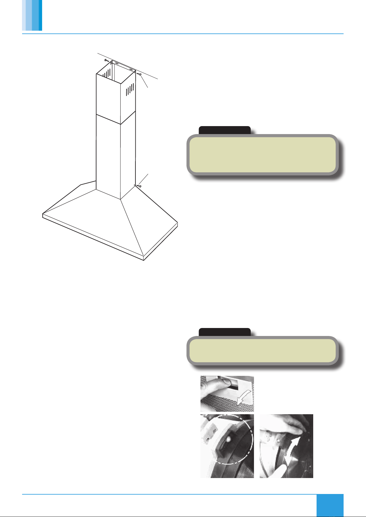
Figure 13. Removing metal grease filters
•Remove the grease filters.
•Hook the carbon filter over the pins that are located at the end of
the motor (Figure 9). Turn the carbon filter clockwise, until you feel
it click into place.
•Repeat this process for the second carbon filter. You need to place
a carbon filter at either end of the motor.
•Refit the grease filters.
4.0 Operation
5.3 Grease Filters
Grease filters collect grease and dust which has a direct effect on the
efficiency of the cooker hood. If not cleaned, the (potential flammable)
grease residue will saturate on the filter. Clean the filter every month
to prevent any risk of fire.
Remove the grease filters by pulling down on the handle and pulling
them away from the cooker hood. Soak the grease filter in hot water
and washing up liquid for about an hour. Rinse them off thoroughly
with hot water. Repeat the process if required. Refit the grease filters
once they have dried.
It is important to let the grease filters dry thoroughly before refitting
them in the cooker hood.
5.4 Lights
Prior to touching the light bulbs ensure they are cool. Find the bulb
that requires replacement, you will find it located in the light fixture
which is inside the exposed section of the canopy.
Disconnect the light wiring point and remove the bulb holders and
wiring from the hood. Important: It is not possible to replace the bulbs
individually, it will be necessary to obtain the bulbs, bulb holders and
wiring as a complete part (LED light: MAX 1.5W).
Fit the replacement bulbs, bulb holders and wiring in the same manner
as the originals and reconnect the light wiring point.
6.0 Warranty
The 2 year warranty starts from the day of delivery and includes parts
only.
This warranty is void if the equipment is modified without
authorisation, is incorrectly applied, misused, disassembled, or not
installed, commissioned and maintained in accordance with the details
contained in this manual and general good practice.
The product warranty applies to the UK mainland and in accordance
with Clause 14 of our Conditions of Sale. Customers purchasing from
outside of the UK should contact Nuaire International Sales office for
further details.
7.0 After Sales
For technical assistance or further product information, including spare
parts and replacement components, please contact the After Sales
Department.
Other NuAire Ventilation Hood manuals