NuAire COOKERHOODC-SS Instruction Manual

Isolation - Before commencing work on the hood, including
replacing light bulbs make sure that the unit has been
disconnected from the power supply.
1.0 Introduction
The Nuaire high performance Cooker Hood Extract Fan has
500m3/hr extraction capacity through a tangential motor.
It incorporates a simple push button control to generate
speed and lighting.
Noise level: 54 - 62 dB.
Casing shall be manufactured from easy to clean stainless
steel.
The unit is fitted with two, washable metallic grease filters for
quick and easy maintenance.
Code Description appliance: COOKERHOODC-SS
Code Description Carbon filter: CKRH-CF (Pair)
2.0 Dimensions
Fig.1.
Product Dimensions:
Height: 700mm - 1080mm
Width: 600mm
Depth: 500mm
Chimney Section Dimensions:
170mm x 221mm
3.0 Installation
Installation must be carried out by competent personnel
conforming to all statutory and governing regulations.
Electrical connection should be undertaken by a qualified
electrician.
The unit is designed for internal wall mounting (minimum two
people) in the vertical plane with the grease filters directly above
the cooker hob top/burners and is for domestic use only.
Note: when installing the unit ensure that the following
recommended distances are observed between the highest point
on the hob top (including the burners) and the bottom of the
cooker hood.
Electric cookers 700mm
Gas cookers 700mm
Coal/oil cookers 800mm
If the unit is installed for use above a gas appliance then the
provision for ventilation must be in accordance with the Gas
Safety Codes of Practice BS.6172, BS.5440 & BS.6891
(Natural Gas) and BS.5482 (LP Gas) 1994, the Gas Safety
(Installation and Use) Regulations, the Building Regulations
issued by Department of the Environment, the Building
Standards (Scotland) (Consolidated) Regulations issued by
the Scottish Development Department.
Do not alter or modify the specifications of this product in
any way.
3.1 Installation of the unit (general)
■When installed between adjoining wall cabinets, the
cabinets must not overhang the hob.
■The edges of the cooker hood are sharp - so handle the
unit with care, especially during installation and cleaning
Do not clean in behind the grease filters.
■If the room where the cooker hood is to be used contains
a fuel burning appliance such as a central heating boiler
then its flue must be of the sealed or balanced flue type.
If other types of flue or appliances are fitted, ensure that
there is an adequate supply of air in the room.
■To ensure high extraction efficiency of the hood ensure
that the ducting is fire retardant and bends are no more
than 90 degrees. Also ensure the ducting for the extractor
function has the same diameter as the outlet hole all the
way through.
■The cooker hood should not be exposed to a direct heat
source from the cooking devise under it i.e. a naked flame
from a gas burner or heat from electric hobs without a pan
on them.
■Lights on the appliance should only be left on when
using the unit.
1
09. 05. 17. Leaflet Number 671403
COOKERHOODC-SS
High Performance Extract Fan
Installation and Maintenance
The EMC Directive
2014/30/EU
The Low Voltage
directive
2014/35/EU
221mm
170mm
500mm
600mm
40mm
300mm
Min 700/Max 1080
Nuaire: A Trading Division of Polypipe Limited Western Industrial Estate Caerphilly United Kingdom CF83 1NA

2
09. 05. 17. Leaflet Number 671403
Installation and Maintenance COOKERHOODC-SS High Performance Extract Fan
3.2 Installation of the unit
Fig. 2. Remove the metal grease filters.
Fig. 3. Position the hood against the wall that you intend to
install on. Mark the position of the support holes (A) and the
anchoring screw holes (B) that are to be drilled as shown
below.
Using a drill bit with a 8mm dia. make holes in the wall on the
positions marked.
Insert rawl plugs into all the holes.
Fasten the support screws half way in, so they protrude 10mm
out of the wall.
Fig. 4. Hang the hood onto the support screws as show below.
Fully tighten the support screws (A) and then screw the
anchoring screws (B) through the relevant holes in the cooker
hood into the wall and fully tighten.
Connecting to external ducting
Fig. 5. Connect the coupling to the
top of the cooker hood, and then
connect a 125mm ducting hose
(by others) to the coupling.
Fig. 6. The other end of the
hose should be connected
to a discharge outlet that
is suitable for cooking
vapours and should have
a cross section of at
least 150cm2.
The maximum distance
between the coupling
and the discharge
outlet should be
3 metres, with one
90 degree bend.
3.3 Fitting the
two part chimney
Fig. 7a. Take the two chimney
sections C and D.
Rest the bottom of section C
on the top of the hood taking
care to position the tabs on
the chimney section into
the rear of the hood.
Mark the side measurement
of both sides of
chimney section C
onto the wall
with a pencil.
Fig. 7b. Lift chimney section D up until it reaches the ceiling.
Ensure that it is perpendicular
with the hood and chimney
section C. Mark the side
measurement of both sides
of chimney section D onto
the wall with a pencil and
then remove section D Fig. 7b.
Before installation ensure the voltage (V) and
frequency (Hz) indicated on the rating plate are exactly the
same as the voltage and frequency ot the home. The rating
plate is on inside of the hood behind the grease filters.
Connect the unit to the mains supply after the rest of the
installation process has been completed.
A
200
A
BB
Anchoring screw holes
Support screw holes
A
Support screws
B
Anchoring screws
A
B
125mm ducting
Coupling
Wall
vapours to
outside via
discharge
outlet
Cooking vapours
extracted via suitable
discharge outlet
Ducting to
coupling on
Cookerhood
D
C
Pencil
marks
each side
DPencil marks
either side
of section D

WARNING: THIS APPLIANCE MUST BE EARTHED.
It should only be connected by a qualified electrician,
using fixed wiring via a double pole switched fused
spur outlet. (UK ONLY).
Before installation ensure the voltage (V) and
frequency (Hz) indicated on the rating plate are exactly the
same as the voltage and frequency ot the home. The rating
plate is on inside of the hood behind the grease filters.
Connect the unit to the mains supply after the rest of the
installation process has been completed.
3
09. 05. 17. Leaflet Number 671403
Installation and Maintenance COOKERHOODC-SS High Performance Extract Fan
Fig. 8. Take a fixing bracket
and place it between the two
pencil marks that you made
in Fig. 7b.
Keeping the bracket in
contact with the wall,
use a pencil to mark
through the anchoring
holes that are cut out
of the bracket.
Use a 8mm drill bit to
make holes in the wall on
the positions marked and
insert rawl plugs into the
two holes. Fix the bracket
into position with screws.
Now remove both
chimney sections D and C
and fix a second bracket between
the two pencil marks that were made
either side of chimney section C.
Fig. 9. Refit chimney section C
to the hood using the two
screws that are supplied.
Secure the bottom of chimney
section C to the fixing bracket,
using the screws provided.
Slide chimney section D
inside of section C.
Lift chimney section D up to
the ceiling and secure it to the
top fixing bracket using the
screws provided.
3.4 Electrical connection
This cooker hood is intended for fitted and permanent
installation.
The cooker hood’s power cable must be fitted upstream from
the electrical connection, using an omni-polar switch with a
contact distance of at least 3 mm.
The fuse must be rated at 3 amps.
We recommend that the appliance is connected by a qualified
electrician, who is a member of the N.I.C.E.I.C. and who will
comply with the I.E.E. and local regulations. The wires in the
mains lead are coloured in accordance with the following UK
code:
Blue = Neutral, Brown = Live, Green/Yellow = Ground
If you only find two wires in the main’s lead (blue and brown),
then neither must be connected to the earth terminal.
As the colours of the wires in the appliance’s mains lead may
not correspond with the coloured markings identifying the
terminals in your spur box, please proceed as follows:
The blue wire must be connected to the terminal marked “N”
(neutral), or coloured black.
The brown wire must be connected to the terminal marked “L”
(live), or coloured red.
Power consumption: 205Watts
(motor 125Watts + 2 x 40Watt light bulbs)
3.5 Completing the installation
If you are setting the appliance to recirculation mode, then you
should now fit the two carbon filters. See the fitting of “Carbon
Filters” section on page 4.
The electrical connection must correspond to the electrical
requirement noted on the rating plate, which is placed inside
the cooker hood. The appliance should now be connected to the
electrical supply. See 3.4 above for detailed information on the
electrical connection.
Refit the grease filter and then switch on the mains supply to
the appliance. Check that the appliance is operating correctly
by selecting each speed and switching the light bulbs on and off.
3.6 Extraction or circulation mode?
To get optimum performance from your cooker, the air will be
taken out of the room via external ducting.
Unfortunately if you live in a flat or the hood is too far from an
outside wall, this may not be possible. The only alternative is to
recirculate the air.
In recirculation mode stale air is taken via the grease filter, and
passed through a charcoal filter for purification. The air then
re-enters the kitchen via an opening in the hood.
What is a carbon filter and do I need one?
All cooker hoods have a grease filter but if you are using your
cooker hood in recirculation mode, then a carbon filter must be
fitted in addition to the grease filter.
Pencil marks
to mark position
of section D
section D
top bracket
secured with
screws for
Ceiling
section D
bottom bracket
secured with
screws
Cooker hood
Ceiling
Cooker hood
Section D
secured to
fixing bracket
each side
with screws
Section C
secured to
fixing bracket
each side
with screws

3.7 Fitting the carbon filter
If the appliance is being used to be used in recirculation mode
then it is necessary to fit carbon filters. This will help to absorb
unpleasant odours caused by cooking.
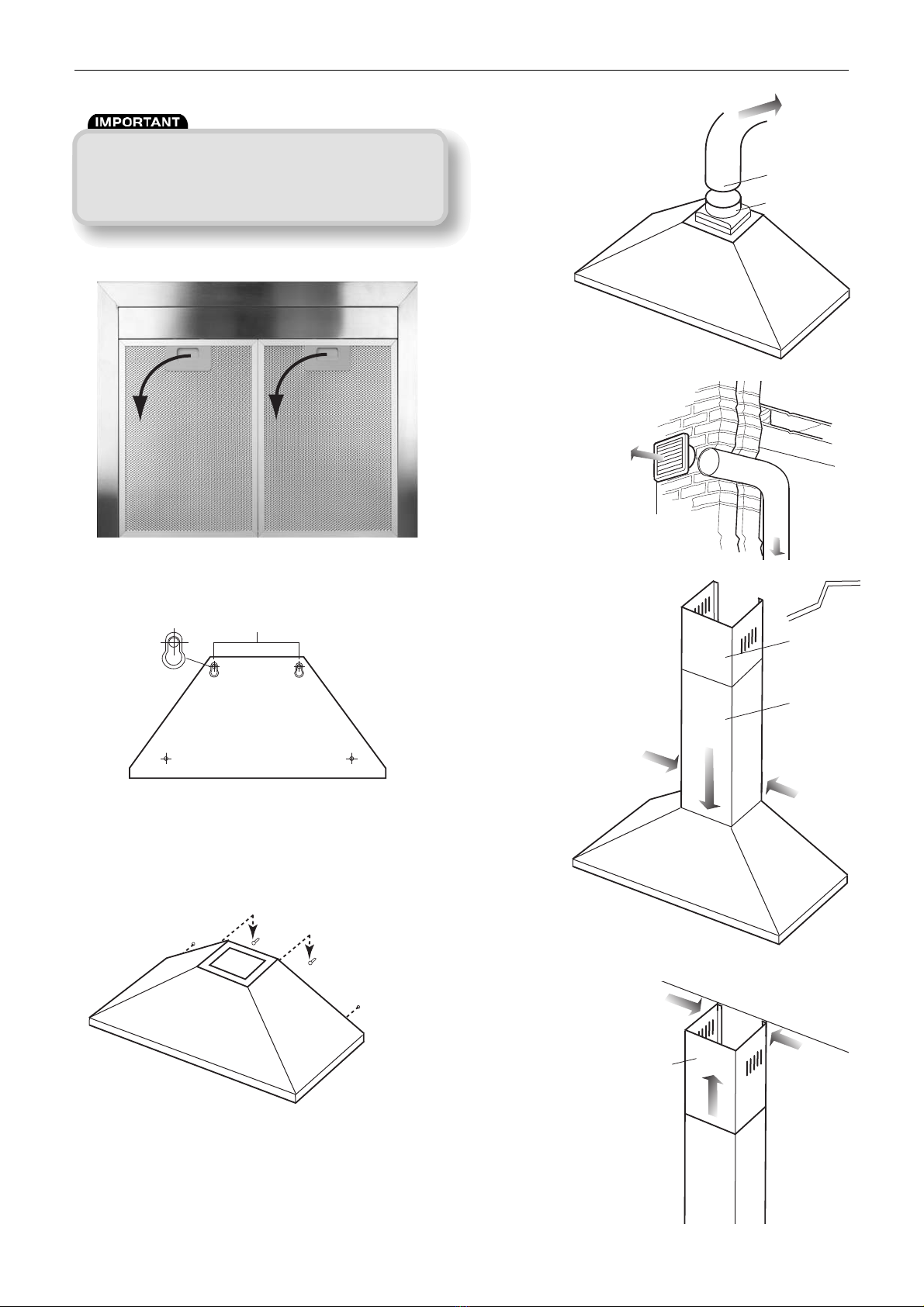
Fig. 10. Remove the grease filters.
Repeat this process for the second carbon filter. You need to
place a carbon filter at either end of the motor.
Refit the grease filters. The carbon filters should be replaced
every three months or if they show signs of damage.
4.0 Using the cooker hood
Important: this process must be followed before the cooker
hood is used for the first time.
■You should use a good quality stainless steel cleaner on
ALL of the stainless steel areas of your cooker hood,
before it is used for the first time.
■This will help to leave a silicone water-resistant film to
protect the stainless steel surfaces.
Fig. 13. How to use the cooker hood control panel:
■Find the control panel, which is located at the front
right of the canopy.
■There are several buttons on the control panel, which
perform separate functions.
■A = ON/OFF button
■B = Speed selection buttons
Low speed
Medium speed
High speed
■o C = Light on/off button
5.0 Cleaning your cooker hood
Important: before cleaning, always ensure that you have
switched your cooker hood off at the omni-polar switch,
set at the wall from the cable.
■Clean the external parts of your cooker hood with mild liquid
detergent and a new damp cloth.
■Never use abrasive powder, corrosive solvents or brushes.
■Never insert pointed objects into the motor’s protective grid.
■Only clean the control panel and grease filter grill with mild
liquid detergents and a new damp cloth.
■If you are using the appliance in recirculation mode,
then be sure to replace the carbon filter at the recommended
interval (see section opposite on “Fitting the carbon filter”). A
build up of grease could cause a fire hazard.
■Never attempt to clean the area above the grease filters.
6.0 Removing and cleaning the
grease filters
First remove the grease filters by pulling down on the
handle and pulling them away from the cooker hood.
■Soak the grease filter in hot water and washing up
liquid for about an hour.
■Rinse them off thoroughly with hot water.
■Repeat the process if required.
■Refit the grease filters once they have dried.
■IMPORTANT: Let the grease filters dry thoroughly
before refitting them in the cooker hood.
7.0 Changing a light bulb
Important: before attempting to change a light bulb, you
must ensure that you have disconnected the cooker hood
from your mains supply.
■Remove the grease filters.
■Prior to touching the light bulbs ensure they are cool.
■Find the bulb that requires replacement in the light fixture
which is inside the exposed section of the canopy.
■Unscrew the light bulb that needs to be replaced and insert a
new E14 40W (max) bulb.
■Defective bulbs should be replaced immediately.
■If the lights still do not work, make sure that the lamps are
fitted properly into their housings before you call for technical
assistance.
■Refit the grease filters.
8.0 Warranty
The 2 year warranty starts from the day of delivery and
includes parts only.
This warranty is void if the equipment is modified without
authorisation, is incorrectly applied, misused, disassembled,
or not installed, commissioned and maintained in accordance
with the details contained in this manual and general good
practice.
The product warranty applies to the UK mainland and in
accordance with Clause 14 of our Conditions of Sale.
Customers purchasing from outside of the UK should
contact Nuaire International Sales office for further details.
9.0 After Sales
For technical assistance or further product information,
including spare parts and replacement components, please
contact the After Sales Department.
Technical
Support on
029 2085
8400
4
WARNING: Before attempting to fit or remove the
carbon filters, you must ensure that you have
disconnected the cooker hood from your mains supply.
09. 05. 17. Leaflet Number 671403
Installation and Maintenance COOKERHOODC-SS High Performance Extract Fan
A B C
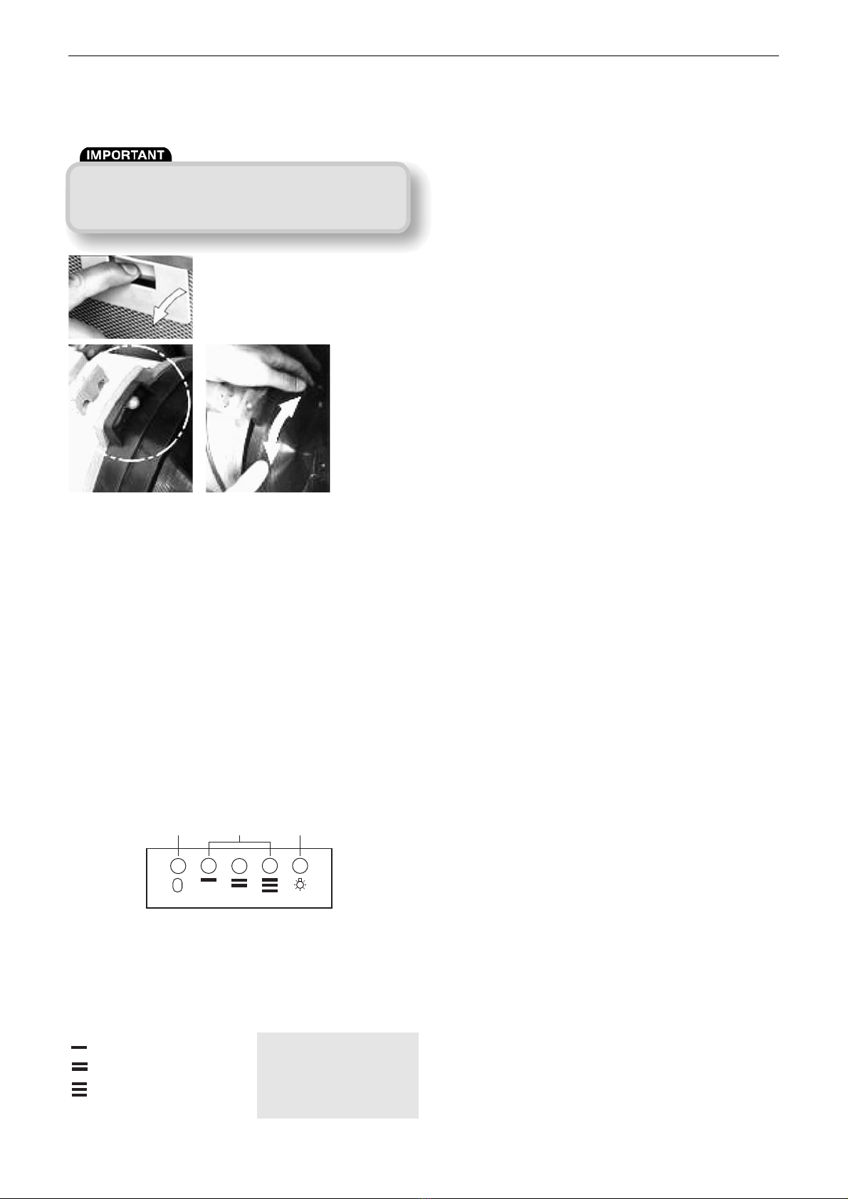
Fig. 11. Hook the carbon
filter over the pins that
are located at the end
of the motor.
Fig. 12. Turn the carbon filter
anticlockwise, until you feel it
click into place.
Table of contents
Other NuAire Ventilation Hood manuals
Popular Ventilation Hood manuals by other brands

Broan
Broan Pro-Style RP1 Series Specification sheet

Novy
Novy 706 installation instructions

Faber
Faber CRISTAL installation instructions

Kleenmaid
Kleenmaid KCRHSO6010 Instructions for use and warranty details

KOBE
KOBE CH8136SQ Installation instructions and operation manual

KOBE
KOBE CH0130SQB (30") installation instructions